Download to read offline


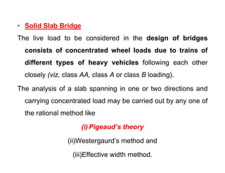
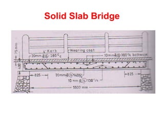
![• Solid Slab Bridge
7.5m1m W W
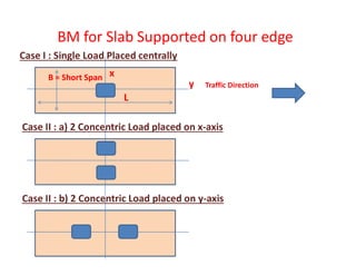
Dead Load Bending Moment = w l2 / 8
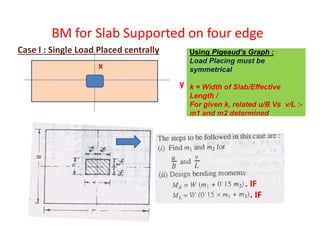
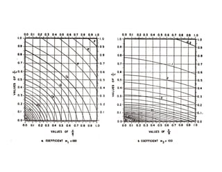
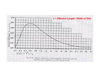
Live Load Bending Moment by Pigeaud’s theory/Curve
10m
Effective depth required :
d = Sqrt [BM / (R x b)]
Area of Reinforcement required
:
= M / (j x d x σst )
R = Moment of Resistance factor
= 0.5 (σcbc . j . K)
d = effective depth
j = lever arm factor = (1- k/3)
k = neutral axis factor = n/d
= (m. σcbc )/(m. σcbc + σst )
σst = 240 N/mm2 for fy = 500 N/mm2](https://image.slidesharecdn.com/1-200124050325/85/1-5-class-c-d-e-5-320.jpg)


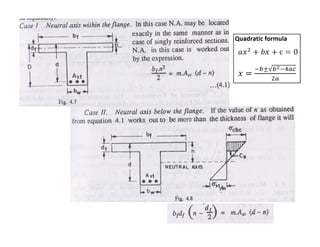
![T-Beam Designed as Singly Reinforced Beam
Effective depth required :
d = Sqrt [BM / (R x b)]
Area of Reinforcement required :
= M / (j x d x σst )
R = Moment of Resistance factor
= 0.5 (σcbc . j . K)
d = effective depth
j = lever arm factor = (1- k/3)
k = neutral axis factor = n/d
= (m. σcbc )/(m. σcbc + σst )
σst = 240 N/mm2 for fy = 500 N/mm2
σcbc= fck /3](https://image.slidesharecdn.com/1-200124050325/85/1-5-class-c-d-e-29-320.jpg)


![EffectivedepthrequiredforWallorSlab
d=Sqrt[BM/(Rx1000)]mm
AreaofReinforcementrequiredforWallorSlab
=M/(jxdx
EffectivedepthrequiredforWallorSlab
d=Sqrt[BM/(Rx1000)]mm
AreaofReinforcementrequiredforWallorSlab
=M/(jxdxσst)](https://image.slidesharecdn.com/1-200124050325/85/1-5-class-c-d-e-38-320.jpg)

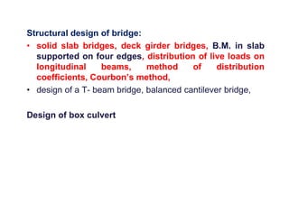
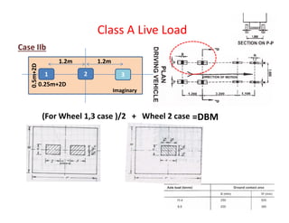
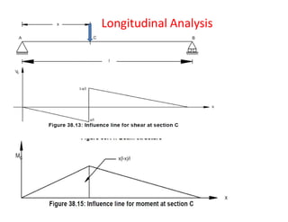
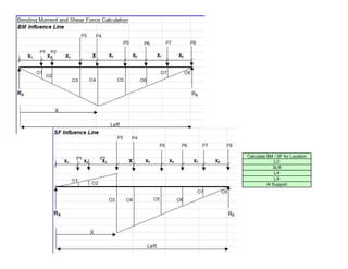
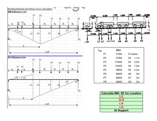
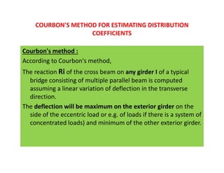
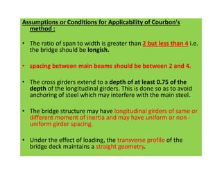
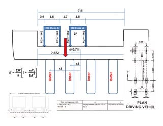
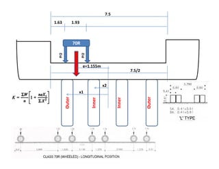
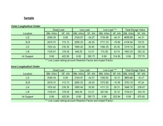
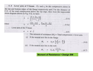
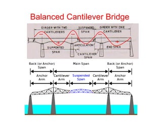
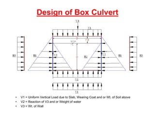
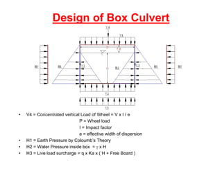
This document provides information on the structural design of bridges and culverts. It discusses the design of solid slab bridges, T-beam bridges, and balanced cantilever bridges. It also covers the distribution of live loads on bridge slabs using methods like Pigeaud's theory and Courbon's method. Finally, it summarizes the design process for box culverts, including determining load cases and calculating bending moments and reinforcement requirements.