Ch4 Bridge Floors (Steel Bridges تصميم الكباري المعدنية & Prof. Dr. Metwally Abu-Hamd)
•
12 likes•2,355 views

Ch4 Bridge Floors (Steel Bridges تصميم الكباري المعدنية & Prof. Dr. Metwally Abu-Hamd)

Recommended
More Related Content
What's hot
What's hot (20)
Similar to Ch4 Bridge Floors (Steel Bridges تصميم الكباري المعدنية & Prof. Dr. Metwally Abu-Hamd)
Similar to Ch4 Bridge Floors (Steel Bridges تصميم الكباري المعدنية & Prof. Dr. Metwally Abu-Hamd) (20)
More from Hossam Shafiq II
More from Hossam Shafiq II (20)
Recently uploaded
Recently uploaded (20)
Ch4 Bridge Floors (Steel Bridges تصميم الكباري المعدنية & Prof. Dr. Metwally Abu-Hamd)
- 1. Chapter 4: Bridge Floors CHAPTER 4 BRIDGE FLOORS
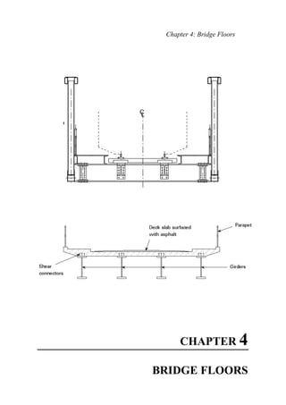
- 2. Steel Bridges CHAPTER 4 BRIDGE FLOORS 4.1 INTRODUCTION The principal function of a bridge deck is to provide support to local vertical loads (from highway traffic, railway or pedestrians) and transmit these loads to the primary superstructure of the bridge, Figure 4.1. In addition to this, the overall structural actions may include: 2. Contributing to the top flange of the longitudinal girders 3. Contributing to the top flange of cross girders at supports and, where present in twin girder and cross girder structures, throughout the span, 4. Stabilizing stringers and cross girders in the transversal direction, 5. Acting as a diaphragm to transmit horizontal loads to supports, 6. Providing a means of distribution of vertical load between longitudinal girders. It may be necessary to take account of these combined actions when verifying the design of the deck. This is most likely to be the case when there are significant stresses from the overall structural actions in the same direction as the maximum bending moments from local deck actions, e.g. in structures with cross girders where the direction of maximum moment is along the bridge.
- 3. Chapter 4: Bridge Floors Fig 4.1 Structural Actions of a Roadway Bridge Deck 4.2 STRUCTURAL SYSTEMS OF BRIDGE FLOORS Structural systems used in bridge floors vary according to the bridge usage as follows: 4.2.1 ROADWAY BRIDGE FLOORS Three main types of transverse structural systems may be used in roadway bridge floors: a) Slab b) Beam-Slab (slab with floor beams) c) Orthotropic plate floor
- 4. Steel Bridges a) In the Slab cross-sections, Fig. 4.2a, a reinforced concrete deck slab about 20 to 30 cm thick is supported directly on the bridge main girders. This system is economical for small spans, generally below 25m, where multiple girders are used for the longitudinal structural system at spacing of 2.5 – 4 m. b) In the Beam-Slab cross-sections, Fig 4.2b, the deck slab is supported on longitudinal floor beams (called stringers) and /or transversal floor beams (called cross-girders). This system is generally adopted for medium spans below 80 m where the spacing of main girders exceeds about 4 m. In both cases, the slab may act independently of the supporting beams (a very uneconomic solution for medium and large spans) or it may work together with the supporting beams (composite bridge deck). The composite action requires the shear flow between the slab and the girders to be taken by shear connectors as shown in Fig. 4.2a. c) In the Orthotropic Plate Deck, Fig. 4.2c, a stiffened steel plate covered with a light wearing surface is welded on top of the main girder webs to provide a deck surface. The deck plate, acting as the top flange of the main girders, gives a very efficient section in bending. The steel plate is longitudinally stiffened by ribs, which may be of open or closed section. Transversally, the ribs are connected through the transverse floor beams (cross girders) yielding a complex grillage system where the main girders, the steel plate, the ribs and the floor beams act together. Fig. 4.2 Roadway Bridge Floors: a) Slab Type Floor
- 5. Chapter 4: Bridge Floors Fig. 4.2 Roadway Bridge Floors: b) Beam Slab Type Floor Fig. 4.2 Roadway Bridge Floors: c) Orthotropic Plate Floors When compared to concrete slab decks, the biggest disadvantage of orthotropic steel plate decks is their high initial cost and the maintenance required. Concrete decks are therefore usually more economic than orthotropic steel plates. The latter are only adopted when deck weight is an important component of loading, i.e. for long span and moveable bridges.
- 6. Steel Bridges 3.2.2 RAILWAY BRIDGE FLOORS Tracks of railway bridges are normally carried on timber sleepers which are 260 cm long and spaced at not more than 50 cm between centers. The sleepers are then supported on the bridge floor system, which may be of the open timber floor type, Fig. 4.3a, or of the ballasted floor type, Fig. 4.3b: a) The Open Floor type consists of longitudinal beams, called stringers, spaced at 1.5 to 1.8 meters, and transversal beams, called cross girders, spaced at 4.0 to 6.0 meters. Fig. 4.3 Railway Bridge Floors: a) Open Timber Floor
- 7. Chapter 4: Bridge Floors b)The Ballasted floor type consists of a 20 cm layer of ballast carried on an R.C. slab which is supported on steel floor beams, e.g.; stringers and/or cross girders as shown in Fig. 4.3b: Fig. 4.3 Railway Bridge Floors: b) Ballasted Floor
- 8. Steel Bridges 4.3 DESIGN CONSIDERATIONS 4.3.1) ALLOWABLE STRESSES FOR STEEL St 52 (ECP 2001) 4.3.1.1) Allowable Stress in Bending Fb 1- Tension and compression due to bending on extreme fibers of “compact” sections symmetric about the plane of their minor axis: Fbx = 0.64 Fy = 2.304 t/cmP 2 In order to qualify under this section: i- The member must meet the compact section requirements of Table 2.1 of ECP. Note that most rolled sections satisfy these requirements. ii-The laterally unsupported length (Lu) of the compression flange is limited by y f u1 F 20b L ≤ bC Fd L y f u2 1380A ≤ 2- Compression on extreme fibers of flexural members meeting the “non- compact” section requirements of Table 2.1of ECP: Fbx = Fltb < 0.58 Fy = 2.1 t/cmP 2 Usually Fltb is governed by: yb fu 1ltb F58.0C A/d.L 800 F ≤= 3- Tension and compression due to bending on extreme fibers of doubly symmetrical I-shape members meeting the “compact” section requirements of Table 2.1(c) of ECP, and bent about their minor axis: Fby = 0.72 Fy = 2.592 t/cmP 2 4.3.1.2) Allowable Stress In Shear: qall = 0.35 Fy = 1.26 t/cmP 2
- 9. Chapter 4: Bridge Floors The effective area in resisting shear of rolled shapes shall be taken as the full height of the section times the web thickness while for fabricated shapes it shall be taken as the web height times the web thickness. 4.3.2) DESIGN OF STRINGER CROSS SECTION Stringers are usually designed as beams simply supported on the cross girders. The maximum straining actions for design are computed from the load positions and load combinations producing the maximum effect on the member considered. The maximum bending stress in the flanges or the maximum shear stress in the web usually governs the cross section size. The stringers are usually connected at their ends to the cross girder by two framing angles which are designed to transmit the maximum end reaction of the stringer to the cross girder, Fig. 4.4a. Stringers may also be designed as continuous beams. In this case the connection between the stringer and the cross girder is designed to carry also the negative moment at the stringer supports, Fig. 4.4b. a) Simple Stringer b) Continuous Stringer Fig. 4.4 Connection between Stringer and Cross Girder In addition to the effect of vertical loads, stringers in open railway bridge floors should be designed to carry the effect of the horizontal loads caused by the lateral shock of the running wheels, see section 2.2 (f). This lateral load is transmitted from the rails to the sleepers and then to the upper flange of the stringer. This effect causes double bending of the stringer cross section. Alternatively, a system of horizontal bracing, called lateral shock bracing, can be arranged between the stringers upper flanges to reduce the effect of lateral loads, Fig. 4.5.
- 10. Steel Bridges Fig. 4.5 Stringer (Lateral Shock) Bracings 4.3.3) DESIGN OF CROSS GIRDER CROSS SECTION Similarly, cross girders are usually designed as beams simply supported on the main girders. The maximum bending stress in the flanges or the maximum shear stress in the web usually governs the cross section size. The cross girders are usually connected at their ends to the main girder by two framing angles which are designed to transmit the maximum end reaction of the cross girder to the main girder. Cross girders of open railway bridge floors are designed to carry the effect of the horizontal loads caused by the longitudinal braking forces. This lateral load is transmitted from the rails to the sleepers and then to the upper flange of the stringers and the cross girders. This effect causes double bending of the cross girder section. Alternatively, a system of horizontal bracing, called braking force bracing, can be arranged between the stringers and the cross girders to eliminate the effect of longitudinal loads, see Fig. 4.6 Fig. 4.6 Cross Girder (Braking Force) Bracings
- 11. Chapter 4: Bridge Floors 4.4 DESIGN EXAMPLES 4.4.1) EXAMPLE 1: ROADWAY BRIDGE FLOOR
- 12. Steel Bridges 4.4.1.1) STRINGER Structural System: Beam supported on cross girders, Span = 4.50 m, Spacing = 1.75 m. 1) Straining Actions: 1.1) Dead Load: • 22 cm Deck Slab = 0.22 × 2.5 = 0.55 t/mP 2 • 5 cm Asphalt = 0.05 × 2.0 = 0.10 t/mP 2 Total D.L = 0.65 t/mP 2 Own wt of stringer (assumed) = 0.10 t/mP / P uniform load on stringer = 0.65 × 1.75 + 0.1 = 1.238 t/mP / Dead Load Actions: QDL = 1.238 × (4.5) / 2 = 2.784 t MDL = 1.238 × (4.5)P 2 P / 8 = 3.132 mt 1.2) Live Load & Impact: • Impact factor I = 0.4 - 0.008 * L = 0.4-0.008*4.5= 0.364 (L = Loaded Length of main traffic lane = 4.5m) Impact is applied to Main Lane Loads only • Maximum LL Reaction on Intermediate Stringer: Place 10P t P on stringer and add effect of 5 P t P @ 1 m: P = 10 * (1 + 0.364) + 5 × (1.75-1)/1.75 = 15.783 t
- 13. Chapter 4: Bridge Floors Loads position for Max Moment: Note: For Lst < 2.6 m: Mmax occurs at the middle section with one LL reaction load acting in the middle. For Lst > 3.4 m: Mmax occurs at the middle section with all three loads acting as shown; For 2.6 < Lst < 3.4 m: Mmax occurs with two LL reaction loads placed such that the stringer centerline bisects the distance between the resultant and one load. MLL & I = 23.674 × 2.25 – 15.783 × 1.5 = 29.592 mt • Loads position for Max Shear: Notes: For L > 3.0 m: Qmax occurs at support with two loads acting on span For L > 3.0 m: Qmax occurs at support with all three loads acting as shown: QLL&I = 15.783 + 15.783 × (3/4.5) + 15.783 × (1.5/4.5) = 31.566 t Bending Moment Shear Force
- 14. Steel Bridges 1.3) Design Straining Actions: The total design moment on an intermediate stringer is: at middle section: Mdesign = 3.132 + 29.592 = 32.724 mt The total design shear on an intermediate stringer is: At support: Qdesign = 2.784 + 31.566 = 34.35 t 2) Design of Cross Section: 2.1) Case of Simple Stringer: Straining Actions: Mx = 32.724 m.t. (Maximum near middle) Qy = 34.504 t (Maximum at support) Design for Bending then check shear. Section is compact w.r. to both local buckling requirements (being a rolled section), and lateral torsional buckling requirements (compression flange supported by deck slab); i.e. Fbx = 0.64 Fy = 2.304 t/cm2 Req. Zx = Mx / Fbx 32.72 x 100 / 2.304 = 1420 cm3 --------- use IPE 450 Bending Stress: fbx = 32.72 x 100 / 1500 = 2.18 t/cm2 < 2.304 t/cm2 OK Check of Fatigue: Actual Stress Range = fsr =(0.5 x 29.592)x100/1500 = 0.9984 t/cm2 < Allowable Stress Range = Fsr = 1.26 t/cm2 (Assuming Class B detail under 2x10⁶ cycles (Case 1.2 of Group 1 ECP) Check Shear: qy = Q / Aw net = 34.504 / (0.85 x 45 x 0.94) = 0.95 t/cm2 < 1.26 t/cm2 OK 2.2) Case of Continuous Stringer: i) Section at mid span : Mx = 0.80 x32.72 = 26.20 m.t.,
- 15. Chapter 4: Bridge Floors Section is compact (see above): Req. Zx = Mx / Fbx = 26.20 x 100 / 2.304 = 1137 cm3 Use IPE 400 Check is similar to case 2.1 above. ii) Section at support : Mx = 0.75 x 32.72 = 24.54 m.t. Compression flange (being at the bottom) is laterally unsupported, therefore the section is assumed non-compact for simplicity. (Usually Lu > Lu1, Lu2) i.e., Fbx = 0.583 Fy = 2.10 t/cm2 . Use IPE 450: fbx = Mx / Zx net = 24.54 x 100 / (0.85x1500) = 1.925 t/cm2 < 2.10 t/cm2 OK (Note: Net section properties were used to account for the moment bolted connection) Check Shear: q = Q / Aw net = 34.504 / (0.85 x 45 x 0.94) = 0.95 t/cm2 < 1.26 t/cm2 OK Equivalent Stresses due to combined shear and bending: all 22 e F1.1q3ff ≤+= = 2.436 t/cm2 > 1.1 x 2.1 = 2.31 N.G., Use IPE 500. 4.4.1.2) CROSS GIRDER Structural System: Beam supported on main girders Span = 7 m, Spacing = 4.5 m 1) Straining Actions: 1.1) Dead Load Effect: Concentrated reaction from stringers = 2 × 2.784 = 5.568 t Own weight of Cross Girder (assumed) = 0.3 t/m/
- 16. Steel Bridges QDL = 3 × 5.568/2 + 0.3 × 7 / 2 = 9.402 t MDL = 11.70 × 3.5 – 5.568 ×1.75 - 0.3 × (3.5)2 /2 = 21.326 mt 1.2) Live Load & Impact Effect: Impact I = 0.4 - 0.008 L = 0.4 × 0.008 (2×4.5) = 0.328 {L = larger of 2 Lst (directly loaded members) or Lxg (indirectly loaded member)} Impact is applied to Main Lane only • Max LL Reactions on Cross Girder: a) From Main Truck: P60 = 10 x (1+0.328) + 2 x 13.28 x 3/4.5 = 30.987 t b) From Main Lane Uniform Load: w60 = 2 [ 0.5x1.328 x 0.75/4.5] = 0.331 t/m/ c) From Secondary Truck: P30 = 5+ 2 x 5x 3/4.5 = 11.667 T d) From Secondary Lane Uniform Load: w30 = 2 [ 0.3x 1.5 x 0.75/4.5] = 0.15 t/m/ N.B.: Uniform load on Lane Fractions on both sides of trucks is to be neglected.
- 17. Chapter 4: Bridge Floors • Loads position for Max Moment: Mmax occurs at the middle with loads placed as shown: MLL & I = 96.88 mt • Loads position for Max Shear: Qmax occurs at support with loads placed as shown: QLL&I = 64.24 t 1.3) Design Straining Actions: The total design moment on an intermediate cross girder is: At the middle section: Mdesign = 21.326 + 96.88 = 118.206 mt And the total design shear on an intermediate cross girder is: At the support: Qdesign = 9.402 + 64.24 = 73.74 t
- 18. Steel Bridges 2) Design of Cross Section: Straining Actions: Mx = 118.206 m.t. (Maximum near middle) Qy = 73.74 t (Maximum at support) Section is compact w.r. to both local buckling requirements (being a rolled section), and lateral torsional buckling requirements (comp flange supported by deck slab); i.e. Fbx = 0.64 Fy = 2.304 t/cm2 Req. Zx = Mx / Fbx = 118.206 x 100 / 2.304 = 5121 cm3 --------- use HEA 650 fbx = 118.206 x 100 / 5470 = 2.157 t/cm2 < 2.304 t/cm2 OK Check of Fatigue: Actual Stress Range = fsr =(0.5 x 96.88)x100/5470 = 0.886 t/cm2 < Allowable Stress Range = Fsr = 1.26 t/cm2 (Assuming Class B detail under 2x10⁶ cycles (Case 1.2 of Group 1 ECP) Check Shear: q = Q / Aw net = 73.74 / (0.85 x 64 x 1.35) = 1.00 t/cm2 < 1.26 t/cm2
- 19. Chapter 4: Bridge Floors 4.4.2) EXAMPLE 2: RAILWAY BRIDGE FLOOR
- 20. Steel Bridges 4.4.2.1) STRINGER Structural System: Beam supported on cross girders, Span = 4.50 m, Spacing = 1.80 m. 1) Straining Actions: 1.1) Dead Load: Track (rails, sleepers, conn. ) = 0.6 t/m/ of track = 0.3 t/m/ of stringer Own wt of stringer (assumed) = 0.15 t/m/ uniform load on stringer =0.3 + 0.15 = 0.45 t/m/ Dead Load Actions: QDL = 0.45 × (4.5) / 2 = 1.013 t MDL = 0.45 × (4.5)2 / 8 = 1.139 mt 1.2) Live Load & Impact: • Impact factor I = 24/(24+ L) = 24/(24+4.5)= 0.842 (max 0.75) (L = Loaded Length of track = 4.5 m) • Loads position for Max Moment: For L < 3.4 m: Mmax occurs with single wheel on stringer For 3.4 < L < 4.4 m: Mmax occurs with two wheels on stringer For L > 4.4 m: Mmax occurs with three wheels on stringer MLL & I = ((3x12.5/2)x2.25-12.5x2) x(1+I) = 30.08 mt
- 21. Chapter 4: Bridge Floors • Loads position for Max Shear: For L > 3.0 m: Qmax occurs at support with three loads acting as shown: QLL&I = (12.5+12.5x2.5/4.5+12.5x.5/4.5) x (1+I) = 36.46 t 1.3) Lateral Shock Effect: a) If No Stringer Bracing is used: My = 6 x 4 /4 = 6 m.t. ( at middle) (Corresponding Mx = 25.51 m.t. ) b) If Stringer Bracing is used: My = 6 x 2 / 4 =3 m.t. ( at quarter point) Corresponding Mx = 0.9 + 21.875 = 22.775 m.t. )
- 22. Steel Bridges 1.4) Design Straining Actions: The total design moment on an intermediate stringer is: a) If No Stringer Bracing is Used: Critical Section at Middle Mx = 1.139 + 30.08 = 31.219 mt My = 6.75 mt b) If Stringer Bracing is Used: Critical Section at Quarter Point Mx = 25.38 mt My = 3.375 mt And the total design shear on an intermediate stringer is: At support: Qy = 1.013 + 36.46 = 37.473 t 1.5) Design of Cross Section: 1.5.1) Case of Simple Stringer without Lateral Shock (stringer) Bracing: Straining Actions: Mx = 31.94 m.t., My = 6.75 m.t. (carried by top flange only) Qy = 37.47 t Section is compact w.r. to local buckling requirements (being a rolled section), but not compact w.r. to lateral torsional buckling requirements (comp flange unsupported for Lun= 4.5m); i.e., Fbx = 0.583 Fy = 2.10 t/cm2 Fby = 0.72 Fy = 2.592 t/cm2 (Minor axis bending) Section HEB 400 fbx = 31.94 x 100 / 2880 = 1.1 t/cm2 < 2.10 t/cm2 OK fby = 6.75x 100 / (721/2) = 1.87 t/cm2 < 2.592 t/cm2 OK Combined Bending: fbx / Fbx + fby / Fby = 1.1/2.10 + 1.87/2.592= 1.24 < 1 x 1.2 (Factor 1.2 accounts for additional stress of Case II loads) Unsafe then use HEB 450 Check of Fatigue: From Mx : Actual Stress Range = fsr =( 30.08)x100/3551 = 0.847 t/cm2 From My : Actual Stress Range = fsr =( 6.75)x100/(781/2) = 1.728 t/cm2 Total Stress Range = 0.847 + 1.728 = 2.575 t/cm2 > Allowable Stress Range = Fsr = 1.2x 1.26 = 1.512 t/cm2 (Assuming Class B detail under 2x10⁶ cycles (Case 1.2 of Group 1 ECP) Fatigue Check is UNSAFE: increase cross section
- 23. Chapter 4: Bridge Floors Check Shear: q = Q / Aw net = 37.47 / (0.85 x 45 x 1.4) = 0.7 t/cm2 < 1.26 t/cm2 1.5.2) Case of Simple Stringer with Lateral Shock (stringer) Bracing: Straining Actions: Mx = 28.25 m.t., My = 3.375 m.t. (at quarter point) Qy = 37.47t at support & Qy = 22.325t at quarter point Section is compact w.r. to both local buckling requirements (being a rolled section), and w.r. to lateral torsional buckling requirements (comp. flange supported at Lun= 2.25 m by stringer bracing); i.e., Fbx = 0.64 Fy = 2.304 t/cm2 Fby = 0.72 Fy = 2.592 t/cm2 (Minor axis bending) Section HEA 360 fbx = 28.25 x 100 / 1890 = 1.495 t/cm2 < 2.304 t/cm2 OK fby = 3.375 x 100 / (526/2) = 1.283 t/cm2 < 2.592 t/cm2 OK Combined Bending: fbx / Fbx + fby / Fby = 1.495/2.304 + 1.283/2.592 = 1.144 < 1 x 1.2 (Factor 1.2 accounts for additional stress of Case II loads) Check of Fatigue is similar to case above. Check Shear at support: q = Q / Aw net = 37.47 / (0.85 x 35 x 1.0) = 1.259 t/cm2 < 1.26 t/cm2 OK 1.5.3) Case of Continuous Stringer without Lateral Shock Bracing: i) Section near mid span: Mx = 0.8 x 31.94= 25.552 m.t., My = 6.75 m.t. (not affected by continuity) Section is compact w.r. to local buckling requirements (being a rolled section), but not compact w r to lateral torsional buckling requirements (comp flange unsupported for Lun= 4.5 m); i.e., Fbx = 0.583 Fy = 2.10 t/cm2 Fby = 0.72 Fy = 2.592 t/cm2 (Minor axis bending) Section HEB 400 fbx = 25.552 x 100 / 2880 = 0.887 t/cm2 < 2.10 t/cm2 OK
- 24. Steel Bridges fby = 6.75 x 100 / (721/2) = 1.872 t/cm2 < 2.592 t/cm2 OK Combined Bending: fbx / Fbx + fby / Fby = 0.887/2.10 + 1.872/2.592= 1.145 <1x 1.2 (Factor 1.2 accounts for additional stress of Case II loads) ii) Section at support : Mx = 0.75 x 31.94 = 23.955 m.t., My = 0, Qy = 37.47 t Compression flange (being at the bottom) is laterally unsupported, therefore the section is non-compact; Use HEB360: for y f u F 20b L ≤ = 316 cm, therefore: Fbx = 0.583 Fy = 2.10 t/cm2 fbx = Mx / Zx net =23.955 x 100 / (0.85 x 2400) = 1.174 t/cm2 < 2.10 t/cm2 OK q = Q / Aw net = 37.47 / (0.85 x 36 x 1.25) = 0.980 t/cm2 < 1.26 t/cm2 OK Equivalent Stresses: all 22 e F1.1q3ff ≤+= = 1.993 t/cm2 < 1.1 x 2.1 = 2.31 t/cm2 1.5.4) Continuous Stringer with Lateral Shock (stringer) Bracing: i) Section at mid span: Mx = 0.8 x 28.25= 22.60 m.t. My = 3.375 m.t (at quarter point) Section is compact w.r. to both local buckling requirements (being a rolled section), and lateral torsional buckling requirements (comp. flange supported at Lun=2 m by stringer bracing); i.e., Fbx = 0.64 Fy = 2.304 t/cm2 Fby = 0.72 Fy = 2.592 t/cm2 (Minor axis bending) Section HEB 320 fbx = 22.60 x 100 / 1930 = 1.171 t/cm2 < 2.304 t/cm2 OK fby = 3.375 x 100 / (616/2) = 1.096 t/cm2 < 2.592 t/cm2 OK Combined Bending: fbx / Fbx + fby / Fby = 1.171/2.304 + 1.096/2.592 = 0.931 < 1.2 (Factor 1.2 accounts for additional stress of Case II loads)
- 25. Chapter 4: Bridge Floors Check Shear: q = Q / Aw net = 37.47 / (0.85 x 32 x 1.15) = 1.198 t/cm2 < 1.26 t/cm2 ii) Section at support : See ((1.3) ii) above. 4.4.2.2) CROSS GIRDER Structural System: Beam supported on main girders Span = 5.30 m, Spacing = 4.50 m 2.1) Dead Load Effect: Concentrated reaction from stringers = 2 × 1.013 = 2.026 t Own weight of X.G. (assumed) = 0.3 t/m/ QDL = 2.026 + 0.3 × 5.3 / 2 = 2.821 t MDL = 2.821 x 5.3/2 – 2.026x0.9-0.3 × (2.65)2 /2= 4.6 mt 2.2) Live Load & Impact Effect: • Impact factor I = 24/(24+ L) = 24/(24+ 9)=0.727 (L = Loaded Length of tracks= 2 x 4.5 = 9 m)
- 26. Steel Bridges • Reactions on Cross Girder: P = {12.5 + 2 x 12.5 x 2.5 / 4.5 + 6.25x0.75/4.5}x (1+I) = {12.5 + 2 x 12.5 x 2.5 / 4.5 + 6.25x0.75/4.5}x (1.727) = 47.37t Mmax occurs at the stringer location MLL & I = 47.37 x 1.75 = 82.90 mt Qmax occurs at support: QLL&I = 47.37 t So the total design moment on an intermediate XG is: Mdesign = 4.6 + 82.90 = 87.5 mt And the total design shear on an intermediate XG is: Qdesign = 2.821 + 47.33 = 50.191 t 2.3) Braking Force Effect: a)If Braking Force Bracing is used: Braking force is carried by the braking force bracing without any bending in the Cross Girders. (i.e. My=0) b) If No Braking Force Bracing is used: Total Braking Force on the bridge: B = Sum of train loads on bridge / 7 = 295 / 7 = 42.1 t Braking force is equally divided between cross girders: Braking force/ XG = 42.1 /no of XGs = 42.1/7= 6.02 t
- 27. Chapter 4: Bridge Floors My = ( 6.02 / 2) x 1.75 = 5.26 mt 2.4) Design of Cross Section: 2.4.1) Without Braking Force Bracing: Straining Actions: Mx = 87.50 m.t., My = 5.26 m.t. ( at stringer location) Qy = 50.191 t (at support) Section is compact w.r. to local buckling requirements (being a rolled section), but not compact w.r. to lateral torsional buckling requirements (comp. flange unsupported for Lun=5.3 m); i.e., Fbx = 0.583 Fy = 2.10 t/cm2 Fby = 0.72 Fy = 2.592 t/cm2 (Minor axis bending) Section HEB 600 : fbx = 87.50 x 100 / 5700 = 1.535 t/cm2 < 2.10 t/cm2 OK fby = 5.26 x 100 / (902/2) = 1.166 t/cm2 < 2.592 t/cm2 OK Combined Bending: fbx / Fbx + fby / Fby = 1.535/2.10 + 1.166/2.592 = 1.074 <1.2 OK Check Fatigue as before. Check Shear: q = Q / Aw net = 50.192 / (0.85 x 79 x 1.50) = 0.498 t/cm2 < 1.26 t/cm2 OK 2.4.2) With Braking Force Bracing: My is carried by axial forces in the braking force bracing with the XG subjected to Mx only: Req. Zx = Mx / Fbx = 7.50 x 100 / 2.304 = 3798 cm3 --------- use HEB 550 Check Shear: q = Q / Aw net = 50.192 / (0.85 x 55 x 1.5) = 0.716 t/cm2 < 1.26 t/cm2
- 28. Steel Bridges 4.4.3) CONNECTIONS OF BRIDGE FLOOR BEAMS 4.4.3.1 Calculations of Bolt Resistance: High strength bolts of Grade 10.9 or 8.8 are normally used in bridge constructions. Connections may be designed as Bearing Type (easier in execution) or Friction Type (when slip is not allowed). For Bearing Type Connections: Bolt Resistance = Smaller of Rshear and Rbearing; Rshear = n x (Bolt area x Allowable bolt shear stress) = n x (π d2 /4) x 2 Rbearing = Bolt diameter x Allowable bearing stress x tmin = d x (0.8 Fult) x tmin (n = no. of shear planes, d= bolt diameter, Edge distance≥ 2 d, F ult = 5.2 t/cm2 ) For Friction Type Connections: Bolt Resistance = n x Ps Bolt Diameter Bearing Type Connections Friction Type Connections RS.Shear Rbearing RD. Shear Bolt 8.8 Bolt 10.9 M20 6.28 8.32 tmin 12.56 3.37 4.82 M22 7.60 9.15 tmin 15.20 4.17 5.96 M24 9.04 9.98 tmin 18.08 4.85 6.94 4.4.3.2 Design of Connection between Stringer and Cross Girder: Railway Bridge Floor Data: Stringer: Shear Force = 37.47 t , -ve Moment = 23.955 m.t., section is HEB 360. Cross Girder: HEB 600 2.1) Case of Simple Stringer: Connection is designed for the max shear of stringer using framing angles as shown:. Using M20 HSB Grade 10.9 (Bearing Type):
- 29. Chapter 4: Bridge Floors a)Bolts between stringer web (tw = 1.25 cm) and angle legs: Double shear bolts Rb = 8.32 x 1.25 = 10.4 t = Rleast Number of bolts = Q / Rleast = 37.47 / 10.4 = 3.3 bolts Fatigue Considerations: Case 27.1 of Group 3 of ECP: for Class C; Allowable stress range = 0.91 t/cm2 Rsh = 2 x 2.45 x 0.91 = 4.46 ton = Rsr Number of bolts = Qsr / Rsr = 36.46 / 4.46 = 8.17 too many Either use bolts with larger diameter or use Friction Type Joint: i) Use M24 bolts: Rsh = 2x3.53x0.91 = 6.43 ton = Rsr Number of bolts = Qsr / Rleast = 36.46 / 6.43 = 5.8 Use 6 bolts M24 (Bearing Type) ii) Friction Type Joint: Rsh = 2 x 4.82 = 9.64 ton = Rleast Number of bolts = Qt / Rleast = 37.47 / 9.64 = 3.88 Use 4 bolts M24 (Friction Type) b) Bolts between angle legs and cross girder web: Single shear bolts on two sides: Fatigue governs the design Number of bolts = Qsr / Rsr = 36.46 / (3.53x0.91) = 11.35 Use 12 bolts M24 (6 bolts each side) (Alternative Using Friction Type Bolts: No. of Bolts = 37.47/4.82= 7.77, i.e.; 4 bolts M20 (Friction Type) Each Side) 2.2) Case of Continuous Stringer: Continuity is achieved by using top and bottom plates designed to transmit the flange force: C = T = M-ve / hstr = (0.75x30.08) / 0.36 = 62.667 t Number of bolts = 62.667 / 6.43 = 9.746 use 10 bolts M24 (Bearing Type) each side. (Alternative Using Friction Type Bolts: No. of Bolts = 66.54/4.82=13.8, i.e.; 14 bolts M20 (Friction Type) Each Side) Compute Plate Thickness from: (30 – 4 x 2.6) x t x 2.1 = 66.54 which gives tpl = 1.617 cm Use tpl = 1.80 cm