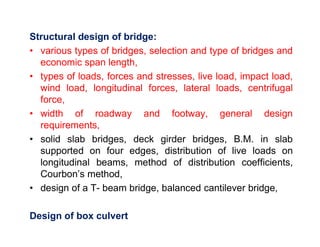
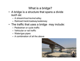
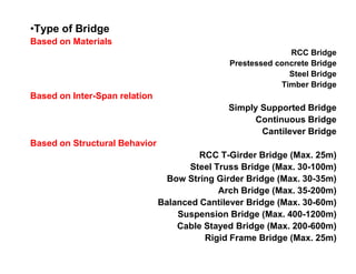
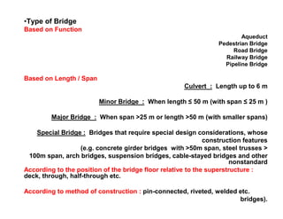
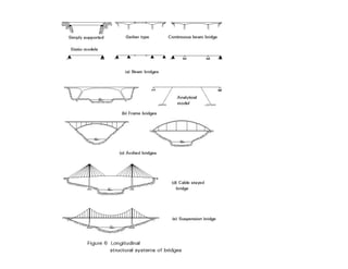
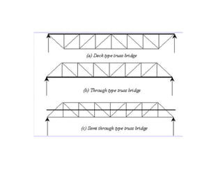
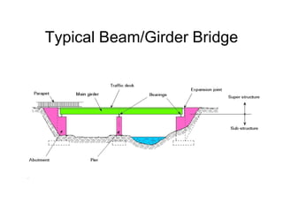
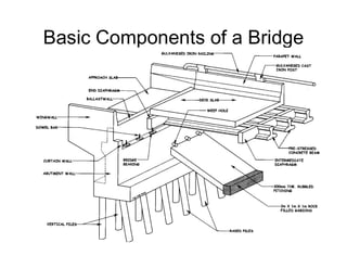
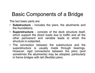
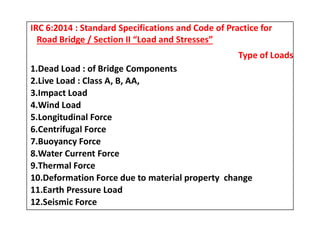
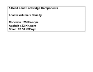
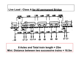
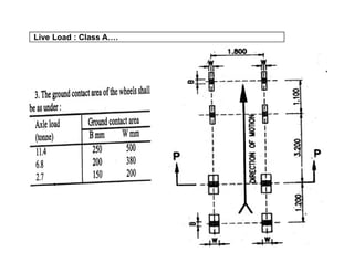
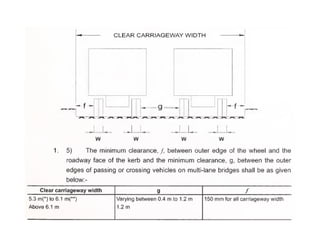
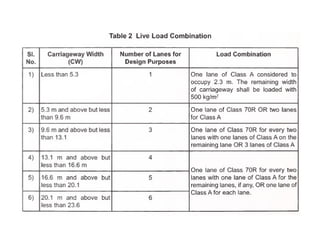
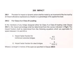
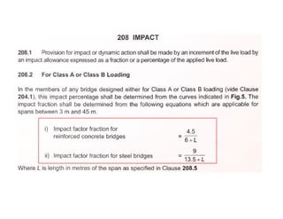
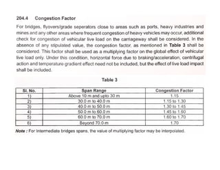
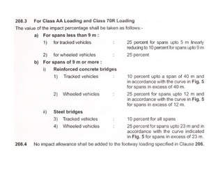
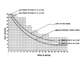
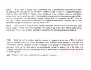
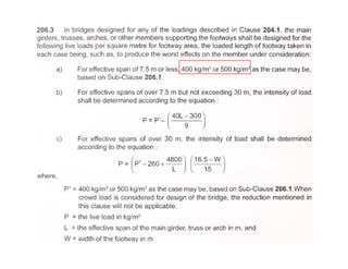
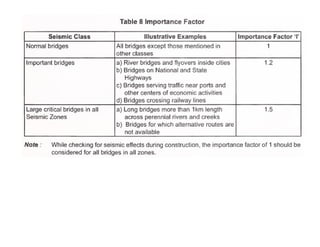
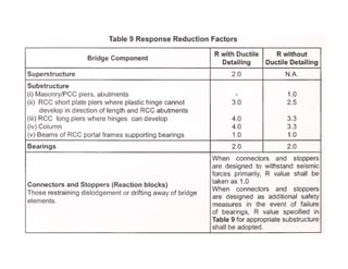
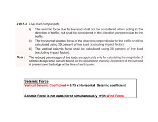
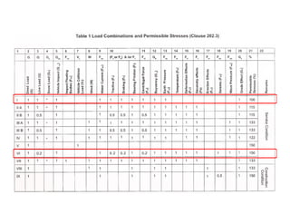
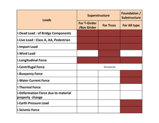
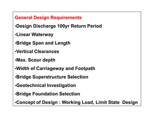
This document discusses structural design considerations for bridges and culverts. It covers types of bridges selected based on span length and economics. It also discusses loads on bridges including dead load, live load, impact load, wind load, and other factors. The document provides details on solid slab bridges, girder bridges, and truss bridges. It also covers design of box culverts.
Workshop under the Capacity Building Programme of the Southern Road Connectivity Project / Expressway Connectivity Improvement Plan Project, March 2016
Friction Considerations : The friction of skid resistance between vehicle tyre and pavement surface is one of the factors determining the operating speed and the minimum distance requires for stopping of vehicles.
Unevenness : The longitudinal profile of the road pavement has to be even' in order to provide a good riding comfort to fast moving vehicles
Light Reflecting Characteristics : Night visibility depends upon the colour and light reflecting characteristics of the pavement surface. The glare caused by the reflection of head lights is considerably high on wet pavement surface than on the dry pavement.
Drainage of Surface Water
Construction Challenges For Bridges In Hilly AreasShantanu Patil
Hilly region pose unique problem for bridge construction. In a restricted hilly area itself climatic condition, Geographical features and hydrological parameters affect considerably. Keeping in view the bridge site and various constraints, type of bridges and method of construction are to be selected carefully for safe, economical and successful completion of bridges construction.
A suspension bridge is a type of bridge in which the deck is hung below suspension cables on vertical suspenders. The basic structural components of a suspension bridge system include stiffening girders/trusses, the main suspension cables, main towers, and the anchorages for the cables at each end of the bridge.
This presentation deals with all the major steps involved in the survey, selection of the most possible route and the designing of the highway.
It will brief u on all the major topics of highway designing
A concise presentation on bridge construction. Related to civil engineering courses. can be helpful for undergraduate students.
Its a Part of my class presentation.
The geometric design of roads is the branch of highway engineering concerned with the positioning of the physical elements of the roadway according to standards and constraints. The basic objectives in geometric design are to optimize efficiency and safety while minimizing cost and environmental damage. Geometric design also affects an emerging fifth objective called "livability," which is defined as designing roads to foster broader community goals, including providing access to employment, schools, businesses and residences, accommodate a range of travel modes such as walking, bicycling, transit, and automobiles, and minimizing fuel use, emissions and environmental damage.
Geometric roadway design can be broken into three main parts: alignment, profile, and cross-section. Combined, they provide a three-dimensional layout for a roadway.
The alignment is the route of the road, defined as a series of horizontal tangents and curves.
The profile is the vertical aspect of the road, including crest and sag curves, and the straight grade lines connecting them.
The cross section shows the position and number of vehicle and bicycle lanes and sidewalks, along with their cross slope or banking. Cross sections also show drainage features, pavement structure and other items outside the category of geometric design.
#source:
1. Highway Engineering by: Khanna & Justo
2. Wikipedia
This presentation helps you to get the conceptual idea about Bridge Superstructures as per the Syllabus of DBATU, Last Year BTech Lonere.
4.1 Bridge Engineering: Super-structures
4.2 Simple bridges or beam bridges: Deck bridges, Through bridges, Semi-through bridges
4.3 Introduction, advantages and disadvantages: Continuous bridges, Cantilever bridges, Arch bridges, Bow-string girder type bridges, Rigid frame bridges, Portal frame bridges, Suspension bridges, Cable-stayed bridges, Composite bridges
4.4 Materials for super-structures: Cement concrete, Masonry, Steel, Timber etc.
A bridge is the key element in a transportation system; it controls both the volume and weight of the traffic. Balance must be achieved between handling future traffic volume and loads and the cost of heavier and wider bridge structure. Economic Analysis and comparisons against competing alternatives is required as Bridges are the most expensive part of a road transportation network. Monetized & Non-Monetized Benefits that will accrue like time savings to road users, benefits to business activities (and to the economy in general) and salvage value benefits like Right-of-Way and substructure use need to be assessed as well.
Railway engineering is a multi-faceted engineering discipline dealing with the design, construction and operation of all types of rail transport systems.
Overview of the fundamental roles in Hydropower generation and the components involved in wider Electrical Engineering.
This paper presents the design and construction of hydroelectric dams from the hydrologist’s survey of the valley before construction, all aspects and involved disciplines, fluid dynamics, structural engineering, generation and mains frequency regulation to the very transmission of power through the network in the United Kingdom.
Author: Robbie Edward Sayers
Collaborators and co editors: Charlie Sims and Connor Healey.
(C) 2024 Robbie E. Sayers
TECHNICAL TRAINING MANUAL GENERAL FAMILIARIZATION COURSEDuvanRamosGarzon1
AIRCRAFT GENERAL
The Single Aisle is the most advanced family aircraft in service today, with fly-by-wire flight controls.
The A318, A319, A320 and A321 are twin-engine subsonic medium range aircraft.
The family offers a choice of engines
Event Management System Vb Net Project Report.pdfKamal Acharya
In present era, the scopes of information technology growing with a very fast .We do not see any are untouched from this industry. The scope of information technology has become wider includes: Business and industry. Household Business, Communication, Education, Entertainment, Science, Medicine, Engineering, Distance Learning, Weather Forecasting. Carrier Searching and so on.
My project named “Event Management System” is software that store and maintained all events coordinated in college. It also helpful to print related reports. My project will help to record the events coordinated by faculties with their Name, Event subject, date & details in an efficient & effective ways.
In my system we have to make a system by which a user can record all events coordinated by a particular faculty. In our proposed system some more featured are added which differs it from the existing system such as security.
Vaccine management system project report documentation..pdfKamal Acharya
The Division of Vaccine and Immunization is facing increasing difficulty monitoring vaccines and other commodities distribution once they have been distributed from the national stores. With the introduction of new vaccines, more challenges have been anticipated with this additions posing serious threat to the already over strained vaccine supply chain system in Kenya.
Student information management system project report ii.pdfKamal Acharya
Our project explains about the student management. This project mainly explains the various actions related to student details. This project shows some ease in adding, editing and deleting the student details. It also provides a less time consuming process for viewing, adding, editing and deleting the marks of the students.
Water scarcity is the lack of fresh water resources to meet the standard water demand. There are two type of water scarcity. One is physical. The other is economic water scarcity.
Courier management system project report.pdfKamal Acharya
It is now-a-days very important for the people to send or receive articles like imported furniture, electronic items, gifts, business goods and the like. People depend vastly on different transport systems which mostly use the manual way of receiving and delivering the articles. There is no way to track the articles till they are received and there is no way to let the customer know what happened in transit, once he booked some articles. In such a situation, we need a system which completely computerizes the cargo activities including time to time tracking of the articles sent. This need is fulfilled by Courier Management System software which is online software for the cargo management people that enables them to receive the goods from a source and send them to a required destination and track their status from time to time.
Democratizing Fuzzing at Scale by Abhishek Aryaabh.arya
Presented at NUS: Fuzzing and Software Security Summer School 2024
This keynote talks about the democratization of fuzzing at scale, highlighting the collaboration between open source communities, academia, and industry to advance the field of fuzzing. It delves into the history of fuzzing, the development of scalable fuzzing platforms, and the empowerment of community-driven research. The talk will further discuss recent advancements leveraging AI/ML and offer insights into the future evolution of the fuzzing landscape.
COLLEGE BUS MANAGEMENT SYSTEM PROJECT REPORT.pdfKamal Acharya
The College Bus Management system is completely developed by Visual Basic .NET Version. The application is connect with most secured database language MS SQL Server. The application is develop by using best combination of front-end and back-end languages. The application is totally design like flat user interface. This flat user interface is more attractive user interface in 2017. The application is gives more important to the system functionality. The application is to manage the student’s details, driver’s details, bus details, bus route details, bus fees details and more. The application has only one unit for admin. The admin can manage the entire application. The admin can login into the application by using username and password of the admin. The application is develop for big and small colleges. It is more user friendly for non-computer person. Even they can easily learn how to manage the application within hours. The application is more secure by the admin. The system will give an effective output for the VB.Net and SQL Server given as input to the system. The compiled java program given as input to the system, after scanning the program will generate different reports. The application generates the report for users. The admin can view and download the report of the data. The application deliver the excel format reports. Because, excel formatted reports is very easy to understand the income and expense of the college bus. This application is mainly develop for windows operating system users. In 2017, 73% of people enterprises are using windows operating system. So the application will easily install for all the windows operating system users. The application-developed size is very low. The application consumes very low space in disk. Therefore, the user can allocate very minimum local disk space for this application.
Automobile Management System Project Report.pdfKamal Acharya
The proposed project is developed to manage the automobile in the automobile dealer company. The main module in this project is login, automobile management, customer management, sales, complaints and reports. The first module is the login. The automobile showroom owner should login to the project for usage. The username and password are verified and if it is correct, next form opens. If the username and password are not correct, it shows the error message.
When a customer search for a automobile, if the automobile is available, they will be taken to a page that shows the details of the automobile including automobile name, automobile ID, quantity, price etc. “Automobile Management System” is useful for maintaining automobiles, customers effectively and hence helps for establishing good relation between customer and automobile organization. It contains various customized modules for effectively maintaining automobiles and stock information accurately and safely.
When the automobile is sold to the customer, stock will be reduced automatically. When a new purchase is made, stock will be increased automatically. While selecting automobiles for sale, the proposed software will automatically check for total number of available stock of that particular item, if the total stock of that particular item is less than 5, software will notify the user to purchase the particular item.
Also when the user tries to sale items which are not in stock, the system will prompt the user that the stock is not enough. Customers of this system can search for a automobile; can purchase a automobile easily by selecting fast. On the other hand the stock of automobiles can be maintained perfectly by the automobile shop manager overcoming the drawbacks of existing system.
Welcome to WIPAC Monthly the magazine brought to you by the LinkedIn Group Water Industry Process Automation & Control.
In this month's edition, along with this month's industry news to celebrate the 13 years since the group was created we have articles including
A case study of the used of Advanced Process Control at the Wastewater Treatment works at Lleida in Spain
A look back on an article on smart wastewater networks in order to see how the industry has measured up in the interim around the adoption of Digital Transformation in the Water Industry.
1. Structural Design of bridge
and Culvert
SDE. Prabhat Kumar Jha
Department of Road
9841360244
2. Structural design of bridge:
• various types of bridges, selection and type of bridges and
economic span length,
• types of loads, forces and stresses, live load, impact load,
wind load, longitudinal forces, lateral loads, centrifugal
force,
• width of roadway and footway, general design
requirements,requirements,
• solid slab bridges, deck girder bridges, B.M. in slab
supported on four edges, distribution of live loads on
longitudinal beams, method of distribution coefficients,
Courbon’s method,
• design of a T- beam bridge, balanced cantilever bridge,
Design of box culvert
3. What is a bridge?
• A bridge is a structure that spans a divide
such as:
– A stream/river/ravine/valley
– Railroad track/roadway/waterway
• The traffic that uses a bridge may include:
– Pedestrian or cycle traffic
– Vehicular or rail traffic– Vehicular or rail traffic
– Water/gas pipes
– A combination of all the above
4. 700 A.D. Asia700 A.D. AsiaNatural BridgesNatural Bridges
Clapper Bridge
Tree trunk
Stone
History of Bridge DevelopmentHistory of Bridge Development
Great Stone Bridge in China
Low Bridge
Shallow Arch
100 B.C. Romans100 B.C. Romans
Stone
The Arch
Natural
Cement
Roman Arch Bridge
Shallow Arch
1300 A.D. Renaissance1300 A.D. Renaissance
Strength of
Materials
Mathematical
Theories
Development of
Metal
5. First Cast-Iron Bridge
Coalbrookdale,
England
1800 A.D.1800 A.D.
History of Bridge DevelopmentHistory of Bridge Development
Truss Bridges
Mechanics of
Design
1900 A.D.1900 A.D.
Prestressed
Concrete
Steel
2000 A.D.2000 A.D.
Coalbrookdale,
England
Britannia Tubular
Bridge
1850 A.D.1850 A.D.
Wrought Iron
Suspension Bridges
Use of Steel for
the suspending
cables
1920 A.D.1920 A.D.
Steel
6. •Type of Bridge
Based on Materials
RCC Bridge
Prestessed concrete Bridge
Steel Bridge
Timber Bridge
Based on Inter-Span relation
Simply Supported Bridge
Continuous Bridge
Cantilever Bridge
Based on Structural Behavior
RCC T-Girder Bridge (Max. 25m)
Steel Truss Bridge (Max. 30-100m)
Bow String Girder Bridge (Max. 30-35m)
Arch Bridge (Max. 35-200m)
Balanced Cantilever Bridge (Max. 30-60m)
Suspension Bridge (Max. 400-1200m)
Cable Stayed Bridge (Max. 200-600m)
Rigid Frame Bridge (Max. 25m)
7. •Type of Bridge
Based on Function
Aqueduct
Pedestrian Bridge
Road Bridge
Railway Bridge
Pipeline Bridge
Based on Length / Span
Culvert : Length up to 6 m
Minor Bridge : When length ≤ 50 m (with span ≤ 25 m )
Major Bridge : When span >25 m or length >50 m (with smaller spans)
Special Bridge : Bridges that require special design considerations, whose
construction features
(e.g. concrete girder bridges with >50m span, steel trusses >
100m span, arch bridges, suspension bridges, cable-stayed bridges and other
nonstandard
According to the position of the bridge floor relative to the superstructure :
deck, through, half-through etc.
According to method of construction : pin-connected, riveted, welded etc.
bridges).
8.
9.
10. Basic Components of a Bridge
The two basic parts are:
• Substructure - includes the piers, the abutments and the
foundations.
• Superstructure - consists of the deck structure itself, which
support the direct loads due to traffic and all the other
permanent and variable leads to which the structure ispermanent and variable leads to which the structure is
subjected.
• The connection between the substructure and the
superstructure is usually made through bearings. However,
rigid connections between the piers (and sometimes the
abutments) may be adopted, particularly in frame bridges with
tall (flexible) piers.
14. • Because the truss is a hollow skeletal
structure, the roadway may pass over or
even through the structure allowing for
clearance below the bridge often not
Truss Bridges
clearance below the bridge often not
possible with other bridge types
15. • Warren Truss
– The Warren truss pattern features a series of isoceles or
equilateral triangles. In contrast to the Pratt and Howe
patterns, the diagonals alternate in direction.
– Warren trusses are typically used in spans of between 150-
Truss Bridges
– Warren trusses are typically used in spans of between 150-
300 feet
– The most common truss. For smaller spans, no vertical
members are used lending the structure a simple look. For
longer spans vertical members are added providing extra
strength
16. Truss Bridges
• Pratt Truss
– The Pratt truss design contains a downward pointing
V in the center with parallel diagonals on each side.
– Except for those diagonal members near the center,
all the diagonal members are subject to tensionall the diagonal members are subject to tension
forces only while the shorter vertical members handle
the compressive forces. This allows for thinner
diagonal members resulting in a more economic
design.
17. • Howe Truss
– The Howe truss pattern features an upward pointing
V formed by the central diagonals with parallel
diagonals on either side. Unlike the Pratt pattern the
diagonals will be in compression when loaded
Truss Bridges
diagonals will be in compression when loaded
– It is the opposite of the Pratt truss. The diagonal
members face in the opposite direction and handle
compressive forces. This makes it very uneconomic
design for steel bridges and is rarely used.
22. Cuts
Cross Overs – Each time a line crosses another line you will need to
make a cut – On one line for this bridge a minimum of 12 cuts will
need to be made!
24. Arch Bridges
• Arches used a curved structure
which provides a high
resistance to bending forces.
• Both ends are fixed in the
horizontal direction (no
horizontal movement allowed
in the bearings).in the bearings).
• Arches can only be used
where ground is solid and
stable.
• Hingeless arch is very stiff and
suffers less deflection.
• Two-hinged arch uses hinged
bearings which allow rotation
and most commonly used for
steel arches and very
economical design.
Hinge-less Arch
Two hinged Arch
25. Arch Bridges
• The three-hinged arch
adds an additional hinge at
the top and suffers very
little movement in either
foundation, butfoundation, but
experiences more
deflection. Rarely used.
• The tied arch allows
construction even if the
ground is not solid enough
to deal with horizontal
forces.
Three-hinged Arch
Tied Arch
27. FACTORS CONSIDERED IN DECIDINGFACTORS CONSIDERED IN DECIDING
BRIDGE TYPEBRIDGE TYPE
••Geometric Conditions of the SiteGeometric Conditions of the Site
••Subsurface Conditions of the SiteSubsurface Conditions of the Site
••Functional RequirementsFunctional Requirements
••AestheticsAesthetics••AestheticsAesthetics
••Economics and Ease of MaintenanceEconomics and Ease of Maintenance
••Construction and Erection ConsiderationConstruction and Erection Consideration
••Legal ConsiderationsLegal Considerations
Selection of Type of Bridge
Principle : The entire completed structure should be the most suitable to carry
the desired traffic , adequate strong to support the incident loads, economical
and aesthetically pleasing.
28. Factors :
1. Hydraulic Factors and River Regime
: Linear Waterway, Scour Depth, x-section at Bridge axis
Ex:- LW > 25m and deep gorge : Steel Truss Bridge or Plate Girder or Arch
Bridge
Ex:- If the scour depth more than 5-7m from Ground Level and Open
Foundation is uneconomical : Steel Truss Bridge
2. Topography and Soil Conditions:
Ex:- Rocky Bank with favorable geological condition may be an ideal site for Arch
Bridge
Ex:- Weak Soil Condition, Simply Supported Bridge rather than Continuous Bridge
29. Factors :
3.A high level structure with uninterrupted traffic as on a National Highway and need
to replace the no. of piers may necessitate a cantilever bridge or a cable stayed
bridge or a series of Simply Supported truss bridge:
4. Large navigational clearances required may dictate the use of particular type such
as Arch Bridge, Cantilever Bridges, cable stayed construction or suspension bridge.
5.The climate and environmental conditions would preclude the use of some type and
require some others.
Ex:- Corrosive Environment , Never Steel BridgeEx:- Corrosive Environment , Never Steel Bridge
6.Shortage of Fund may necessitate the adoption of a submersible bridge instead of
a high level bridge on a road with low volume of traffic.
Ex:- Vented Causeway
7.Type of Traffic restricts choice of type .
Ex:- For Railway most preferred choice is Steel truss Bridge
8.The personal preferences or Company Specialization of designer / construction
firms.
Es:- Hulas always try to design Steel Truss Bridge under Design-Build Contract
30. 9.Availability of Material
Ex:- Remote Hilly region : RCC Bridge truss bridge is last choice.
10.Economy
Cost of Sub-structure more or less equal to Cost of Superstructure
31. •Economic Span of Bridge
Thumb:ForRCCSlabBridge:leconomic=1.5H
ForSteelTrussBridge:Leconomic=3H
Thumb:ForRCCSlabBridge:leconomic=1.5H
ForSteelTrussBridge:Leconomic=3H
32. Choice of Location of Bridge Site
In broader sense, the key factors to be
considered:
1. Hydrological and River Morphological
FactorsFactors
2. Geological and Geotechnical Factors
3. Social and Economic Factors
4. Safety Factors
33. Choice of Location of Bridge Site
A multi disciplinary expert team selects axis based on :-
1. The reach of the river should be straight so min.
disturbance effects on flow due to structures
2. The river in the reach should have a regime flow free of
whirls, eddies and excessive to avoid excessive scour
and construction difficulties
3. The site should have firm high banks that are fairly
inerodable to avoid breaching of the approachesinerodable to avoid breaching of the approaches
4. The site on a meandering river should be a nodal point to
avoid normal shifting of region
5. The approaches for the bank should secure enough to
flash flood / design flood
6. Approaches bank should not be too high or too expensive
to build
7. The site should have reasonable proximity to the main
road.
34. Choice of Location of Bridge Site
8.Site requiring minimum recurring maintenance costs
9.Bridge site and approach slope should be stable and
favorable rock orientation
10.The crossing should provide the shortest possible
line of communication between Demand area and
Supply Area as otherwise its usage will be very muchSupply Area as otherwise its usage will be very much
limited and the intensity of usages will be less.
11.The bridge length should be Shortest and Safe
Practically, the site selection is a matter of judgment.
Various alternatives satisfying many conditions as
possible have to be chosen and put to the economic
test before detailed investigations for a chosen site are
undertaken
38. Basic Components of a Bridge
The two basic parts are:
• Substructure - includes the piers, the abutments and
the foundations.
• Superstructure - consists of the deck structure itself,
which support the direct loads due to traffic and all the
other permanent and variable leads to which the
which support the direct loads due to traffic and all the
other permanent and variable leads to which the
structure is subjected.
• The connection between the substructure and the
superstructure is usually made through bearings.
However, rigid connections between the piers (and
sometimes the abutments) may be adopted, particularly
in frame bridges with tall (flexible) piers.
40. IRC 6:2014 : Standard Specifications and Code of Practice for
Road Bridge / Section II “Load and Stresses”
Type of Loads
1.Dead Load : of Bridge Components
2.Live Load : Class A, B, AA,
3.Impact Load
4.Wind Load
5.Longitudinal Force
6.Centrifugal Force6.Centrifugal Force
7.Buoyancy Force
8.Water Current Force
9.Thermal Force
10.Deformation Force due to material property change
11.Earth Pressure Load
12.Seismic Force
41. 1.Dead Load : of Bridge Components
Load = Volume x Density
Concrete : 25 KN/sqm
Asphalt : 22 KN/sqm
Steel : 78.50 KN/sqm
42. Live Load : Class A for All permanent Bridge
8 Axles and Total train length = 25m
Mini. Distance between two successive trains = 18.5m
57. Wind Load
Dynamic Load but normally approximated to static
load uniformly distributed over the vertical plane /
elevation area
450 kg/sqm
Longitudinal ForceLongitudinal Force
Due to vehicle Braking and Accelerating while passing
the Bridge.
Approximated to 20% of Lane Load applied at 1.2m
above the level of deck
transfer to substructure through bearing
58. Centrifugal Force
For a bridge on horizontal curve, CF developed while vehicle
passing it.
C = Live Load x (Velocity)^2 / (127 x Radius of Curve) at 2m
above the deck Level.
Buoyancy Force
Under water bridge structure can suffer from buoyance force for
very large structure and result in undermining effect.
BF = w x H (Upward)
59. Water Current Force
Horizontal forces are exerted on submerged
part of sub-structures because of water
current, max at top of surface and linearly
reduces to ZERO at bed level.
k = Constant depend on shape of Pier
60. •Type of Loads (IRC 6:2000)
Thermal Force
Tensile forces developed due to temperature fluctuating in temperature at Bearing
LevelLevel
Deformation Force
Due to change in material properties and geometry
: shrinkage, creep
67. Seismic Force
Vertical Seismic Coefficient = 0.75 x Horizontal Seismic coefficient
Seismic Force is not considered simultaneously with Wind Force
68.
69. Loads
Superstructure
Foundation /
Substructure
For T-Girder
/Box Girder
For Truss For All type
1.Dead Load : of Bridge Components
1.Live Load : Class A, AA, Pedestrian
1.Impact Load
1.Wind Load
1.Longitudinal Force1.Longitudinal Force
1.Centrifugal Force Occasional
1.Buoyancy Force
1.Water Current Force
1.Thermal Force
1.Deformation Force due to material
property change
1.Earth Pressure Load
1.Seismic Force
70. NEPAL BRIDGE STANDARDS-2067
DESIGN DISCHARGE
• All permanent bridges shall be designed
for a discharge of 100 yrs. return period.
For the calculation of design dischargeFor the calculation of design discharge
empirical formulas especially developed
for other catchments shall not be used.
71. NEPAL BRIDGE STANDARDS-2067
4.0 BRIDGE LOADINGS
4.1 ROAD BRIDGE LOADINGS
• All permanent road bridges in Nepal shall
be designed as per IRC loadings orbe designed as per IRC loadings or
AASHTO loadings. All design shall be
carried out in accordance to IRC
standards for bridges unless otherwise
specified in this document.
72. NEPAL BRIDGE STANDARDS-2067
5.0 GEOMETRIC STANDARDS
5.1 CARRIAGEWAY
• All bridges in Highways and Urban Roads shall
be designed with a minimum carriageway widthbe designed with a minimum carriageway width
of 7.5m.
• All bridges in Feeder Roads shall be designed
with a minimum carriageway width of 6.0m.
• No permanent bridge shall be designed with a
carriageway width of less than 6.0m except on
minor (district and village) roads having length
less than 25m.
73. NEPAL BRIDGE STANDARDS-2067
5.2 FOOTPATH
• Footpaths shall be provided on all bridges
located at settlement areas or on areas of high
movement of pedestrian traffic. They should bemovement of pedestrian traffic. They should be
separated from the vehicular traffic by safety
curbs (in rural areas) and by raised footpath or
curbs (in urban areas).The width of the footpath
should be decided according to projection of
pedestrian traffic, however, a minimum clear
width(excluding the width of railings) of 1.0
m footpaths to be provided, where necessary.
74. NEPAL BRIDGE STANDARDS-2067
6.0 CLEARANCES
6.1 VERTICAL CLEARANCE
• The vertical clearance of structures shall be,
• For all roads not less than 4.75 m for through• For all roads not less than 4.75 m for through
structures
• Overhead wires, poles etc shall be at least 7.0 m
above the highest point of the road surface.
75. NEPAL BRIDGE STANDARDS-2067
7.0 BRIDGE CLASSIFICATION
Classification of bridges shall be as follows:
Culvert : Length up to 6 m
Minor Bridge : When length 50 m (with span 25 m )Minor Bridge : When length 50 m (with span 25 m )
Major Bridge : When span >25 m or length >50 m(with
smaller spans)
Special Bridge : Bridges that require special design
considerations, whose construction features(e.g.
concrete girder bridges with >50m span, steel trusses >
100m span, arch bridges, suspension bridges, cable-
stayed bridges and other nonstandard bridges).
77. General Design Requirements
•Design Discharge 100yr Return Period
•Linear Waterway
•Bridge Span and Length
•Vertical Clearances
•Max. Scour depth•Max. Scour depth
•Width of Carriageway and Footpath
•Bridge Superstructure Selection
•Geotechnical Investigation
•Bridge Foundation Selection
•Concept of Design : Working Load, Limit State Design