
More Related Content
What's hot
What's hot (20)
Similar to Tony
Similar to Tony (20)
Recently uploaded
Recently uploaded (20)
Tony
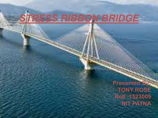
- 1. STRESS RIBBON BRIDGE Presented By: TONY ROSE Roll :1523009 NIT PATNA
- 2. OVERVIEW • Introduction • Form of a stress ribbon bridge • Construction techniques • Modified stress ribbon bridge • Advantages • Applications • Recent advances • Conclusion • References 2SEMINAR ON STRESS RIBBON BRIDGE
- 3. Introduction What is stress ribbon bridge? Special type of suspension bridge where in the cables are embedded in the deck just below the walking surface. Bridge follows a catenary (funicular) profile and sags between supports. 3SEMINAR ON STRESS RIBBON BRIDGE Catenary profile of a stress ribbon bridge
- 4. Introduction(Contd.) Uses the theory of a catenary transmitting loads via tension in the deck to abutments which are anchored to the ground. Concept was first introduced by a German engineer Ulrich Finsterwalder. Prestressing the deck segments stiffens the structure, providing stability to the cables. The first stress ribbon bridge was constructed in Switzerland in the 1960s. The new bridge at Lake Hodges is the sixth ribbon bridge in North America, with three equal spans of 330 feet is the longest of this type. SEMINAR ON STRESS RIBBON BRIDGE 4
- 5. SEMINAR ON STRESS RIBBON BRIDGE 5 Stress ribbon bridge: Modern analogy of ROPE BRIDGE
- 6. Finsterwalder’s Stress Ribbon Bridge Theory : Stress ribbon bridge combines a suspended concave span (radius= 8200ft) and a supported convex span (radius 9800ft,based on design speed of bridge). The stress ribbon itself is a reinforced concrete slab (thickness=25.4cm). Reinforcement consists of three to four layers of 1 inch (2.5cm) to 1 ¼ inch (1.2cm) diameter, high strength steel. Layers are spaced so that the prestressing pipe sleeve couplings can be used as spacers both vertically and horizontally. SEMINAR ON STRESS RIBBON BRIDGE 6
- 7. SEMINAR ON STRESS RIBBON BRIDGE 7 To resist bending moments from traffic, the slab is heavily reinforced at the top and bottom in the transverse direction. The high strength steel tendons are stressed piece by piece during erection to produce the desired upward deflection . A temporary catwalk is provided to stress the first tendons. Concrete is placed from the middle of the freely hanging 63 suspended concave part and continues without interruption to the supports .
- 8. Form of a Stress Ribbon Bridge SEMINAR ON STRESS RIBBON BRIDGE 8 Form of a stress ribbon bridge
- 9. Superstructure 1. Stress ribbon bridge deck consists of precast concrete planks with bearing tendons to support them during construction and separate prestressing tendons which are tensioned to create the final designed geometric form. 2. The prestressing tendons transfer horizontal forces in to the abutments and then to the ground most often using ground anchors. Substructure 1. The abutments are designed to transfer the horizontal forces from the deck cables into the ground via ground anchors. 2. The ground anchors are normally tensioned in 2 stages, the first step is tensioned before the deck is erected and the rest, after the deck is complete. 3. The soil pressure, overturnings and sliding has to be checked for construction. SEMINAR ON STRESS RIBBON BRIDGE 9
- 10. Ground Conditions 1. The ideal ground condition for resisting large horizontal forces from the ribbon is a rock base. 2. In some cases where soil conditions do not permit the use of anchors, piles can also be used. 3. Battered micropiling is another alternative which can resist the load from the ribbon because of its compression and tension capacity. SEMINAR ON STRESS RIBBON BRIDGE 10 deck Lake Hodges Bridge, USA
- 11. Construction Techniques • Abutments and piers are built. • Bearing cables are stretched from abutment to abutment and draped over steel saddles that rested atop the piers. • Precast panels are suspended via support rods located at the four corners of each panel. At this point the bridge sagged into its catenary shape. • Post tensioning ducts are placed directly above the bearing cables and support rods . • The cast-in place concrete was placed and is allowed to harden before the final tensioning is carried out. SEMINAR ON STRESS RIBBON BRIDGE 11
- 12. • Once the concrete is cured and achieved its full strength, the bridge is post tensioned. • The post tensioning lifts each span, closes the gap between the panels, puts the entire bridge in to compression and transforms the bridge in to continuous ribbon of prestressed concrete. SEMINAR ON STRESS RIBBON BRIDGE 12 Construction Techniques(Contd.)
- 13. Modified stress ribbon bridges Stress ribbon bridges stiffened by arches SEMINAR ON STRESS RIBBON BRIDGE 13
- 14. Modified stress ribbon bridges(Contd.) Stress ribbon bridges suspended on arches SEMINAR ON STRESS RIBBON BRIDGE 14
- 15. Static loading test • 1.Vehicles were placed on the entire length of the bridge • 2.Vehicles placed on each span • During the test only the deformations in the middle of the spans and the horizontal displacements of all supports were measured » Prague troja bridge ,Czech Republic SEMINAR ON STRESS RIBBON BRIDGE 15
- 16. Comparison with simple suspension bridge • Similar in many ways to simple suspension bridge • But the suspension cables are embedded in the deck slab • In suspension bridge cables carry the load, but in stress ribbon bridges the highly stiffened deck shares the axial tension • Comparing to simple suspension bridges,both sway and bounce are less in stress ribbon bridges SEMINAR ON STRESS RIBBON BRIDGE 16
- 17. Advantages • Stress ribbon pedestrian bridges are very economical, aesthetical • Minimal environmental and visual impact • Can be erected without falsework or shoring • Minimal long-term maintenance is required • Are highly desirable at places as shown below: SEMINAR ON STRESS RIBBON BRIDGE 17
- 18. Applications Ecoduct Stuttgart trade fair hall roof SEMINAR ON STRESS RIBBON BRIDGE 18
- 19. Recent Advances • Innovative design uses unidirectional solid carbon fibre cables (TSC). • Unsupported spans were significantly increased • Supporting structure was reduced • Installation time and cost were reduced by over 80% SEMINAR ON STRESS RIBBON BRIDGE 19 World’s longest stress ribbon bridge in Cuenca ,Spain
- 20. SEMINAR ON STRESS RIBBON BRIDGE 20
- 21. Conclusion • Stress ribbon bridges are a versatile form of bridge. • Slender decks are visually pleasing and have a visual impact on surroundings giving a light aesthetic impression. • Post tensioned concrete minimises cracking and assures durability. • Bearings and expansion joints are rarely required minimising maintenance and inspections. SEMINAR ON STRESS RIBBON BRIDGE 21
- 22. References • Roma Agrawal, (2009), Stress ribbon bridges, The structural engineer, pp 22-27 • Tomas Kulhavy, (1998), Stress ribbon bridges stiffened by arches or cables, 2nd Int’l phd symposium in civil engineering, Budapest. • Tony Sanchez, (2010), Path to safety, ASCE journal, pp 68-76. • Stress Ribbon Bridges: Mechanics of the Stress Ribbon on the Saddle Arndt Goldack1; Mike Schlaich2; and Moritz Meiselbach • . Preliminary design of prestressed concrete stress Ribbon bridge By Diego Cobo del Arco,1 A´ ngel . Aparicio,2 and Antonio R. Marı´,3 Member, ASCE SEMINAR ON STRESS RIBBON BRIDGE 22
- 23. THANK YOU.. SEMINAR ON STRESS RIBBON BRIDGE 23