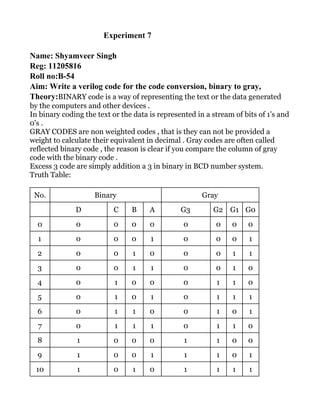
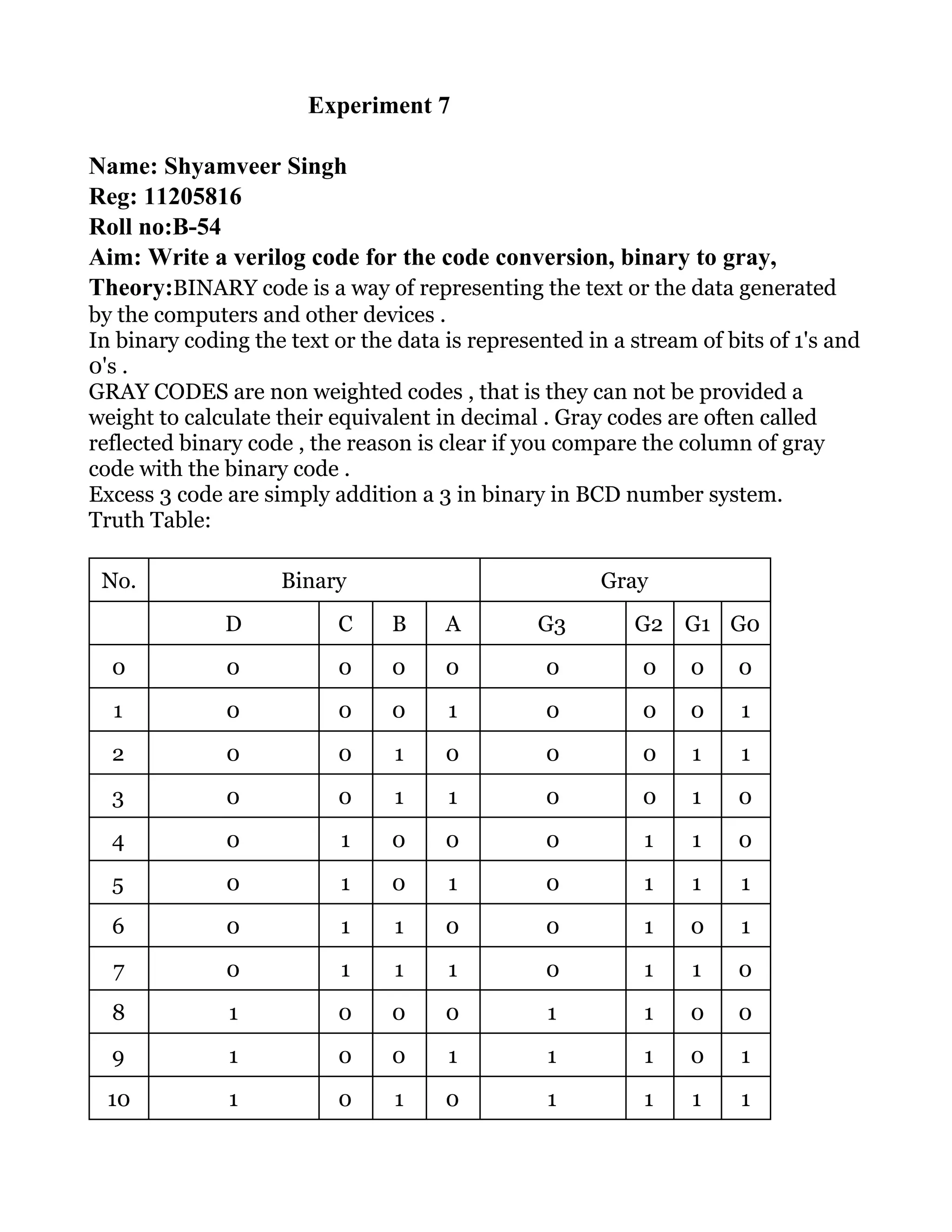
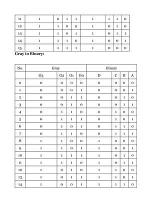
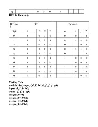
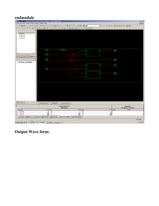
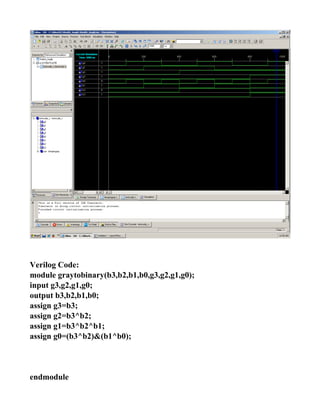
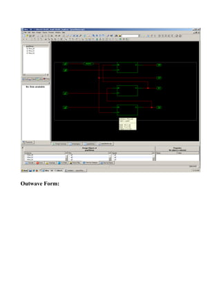
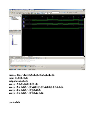
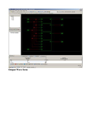
​Experiment 7 
 
Name: Shyamveer Singh 
Reg: 11205816 
Roll no:B­54 
Aim: Write a verilog code for the code conversion, binary to gray, 
Theory:​BINARY code is a way of representing the text or the data generated
by the computers and other devices .
In binary coding the text or the data is represented in a stream of bits of 1's and
0's .
GRAY CODES are non weighted codes , that is they can not be provided a
weight to calculate their equivalent in decimal . Gray codes are often called
reflected binary code , the reason is clear if you compare the column of gray
code with the binary code .
Excess 3 code are simply addition a 3 in binary in BCD number system.
Truth Table:
No. Binary Gray
D C B A G3 G2 G1 G0
0 0 0 0 0 0 0 0 0
1 0 0 0 1 0 0 0 1
2 0 0 1 0 0 0 1 1
3 0 0 1 1 0 0 1 0
4 0 1 0 0 0 1 1 0
5 0 1 0 1 0 1 1 1
6 0 1 1 0 0 1 0 1
7 0 1 1 1 0 1 1 0
8 1 0 0 0 1 1 0 0
9 1 0 0 1 1 1 0 1
10 1 0 1 0 1 1 1 1
11 1 0 1 1 1 1 1 0
12 1 1 0 0 1 0 1 0
13 1 1 0 1 1 0 1 1
14 1 1 1 0 1 0 0 1
15 1 1 1 1 1 0 0 0
Gray to Binary:
No. Gray Binary
G3 G2 G1 G0 D C B A
0 0 0 0 0 0 0 0 0
1 0 0 0 1 0 0 0 1
2 0 0 1 1 0 0 1 0
3 0 0 1 0 0 0 1 1
4 0 1 1 0 0 1 0 0
5 0 1 1 1 0 1 0 1
6 0 1 0 1 0 1 1 0
7 0 1 1 0 0 1 1 1
8 1 1 0 0 1 0 0 0
9 1 1 0 1 1 0 0 1
10 1 1 1 1 1 0 1 0
11 1 1 1 0 1 0 1 1
12 1 0 1 0 1 1 0 0
13 1 0 1 1 1 1 0 1
14 1 0 0 1 1 1 1 0
15 1 0 0 0 1 1 1 1
BCD to Excess-3:
Decima
l
BCD Excess-3
Digit A B C D w x y Z
0 0 0 0 0 0 0 1 1
1 0 0 0 1 0 1 0 0
2 0 0 1 0 0 1 0 1
3 0 0 1 1 0 1 1 0
4 0 1 0 0 0 1 1 1
5 0 1 0 1 1 0 0 0
6 0 1 1 0 1 0 0 1
7 0 1 1 1 1 0 1 0
8 1 0 0 0 1 0 1 1
9 1 0 0 1 1 1 0 0
Verilog Code: 
module binaytogray(b3,b2,b1,b0,g3,g2,g1,g0); 
input b3,b2,b1,b0; 
output g3,g2,g1,g0; 
assign g3=b3; 
assign g2=b3^b2; 
assign g1=b2^b1; 
assign g0=b1^b0; 


endmodule 
 
Output Wave form: 
 
 
Verilog Code: 
module graytobinary(b3,b2,b1,b0,g3,g2,g1,g0); 
input g3,g2,g1,g0; 
output b3,b2,b1,b0; 
assign g3=b3; 
assign g2=b3^b2; 
assign g1=b3^b2^b1; 
assign g0=(b3^b2)&(b1^b0); 


endmodule 
 
 
Outwave Form: 
 
 
module binary2ex3(b3,b2,b1,b0,e3,e2,e1,e0); 
input b3,b2,b1,b0; 
output e3,e2,e1,e0; 
assign e3=b3|b0&b2|b2&b1; 
assign e2=(~b1)&(~b0)&(b2)|(~b2)&(b0)|(~b2)&(b1); 
assign e1=(~b1)&(~b0)|b1&b2; 
assign e0=(~b1)&(~b0)|b1&(~b0); 
 
 
endmodule 
Output Wave form 
 
Result: ​Results are verified, and gatelevel and  behavioral modeling also 
ploted. 
Learning Outcome: 
After performing this experiment we know about the code conversion and how 
to draw a k map , and expressions as well. 

Code conversion using verilog code VHDL