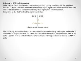
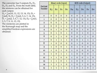
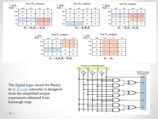
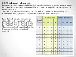
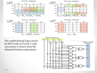
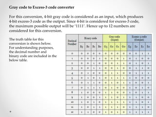
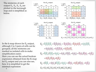
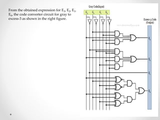
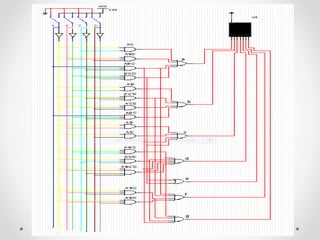
1. The document discusses various types of code conversions including binary to BCD, BCD to excess-3, and gray to excess-3. Circuit designs and truth tables are provided for each conversion.
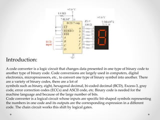
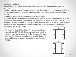
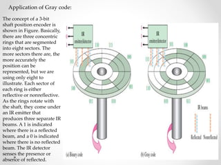
2. Applications of different codes are covered. BCD is used for 7-segment displays. Gray code is used in shaft encoders. Excess-3 is used for subtraction.
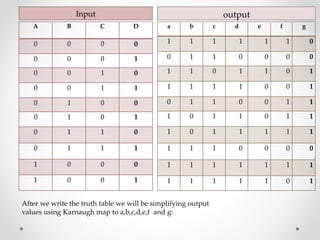
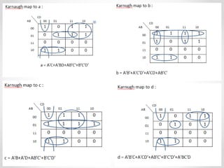
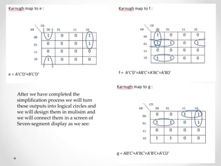
3. The document concludes by designing a BCD to 7-segment display decoder circuit and explaining the application of gray code in shaft encoders.