This document contains the answer key for a unit test on Manufacturing Technology-II. It discusses various topics related to cutting tools and machining processes, including:
1. Types of cutting tools such as single point and multipoint tools.
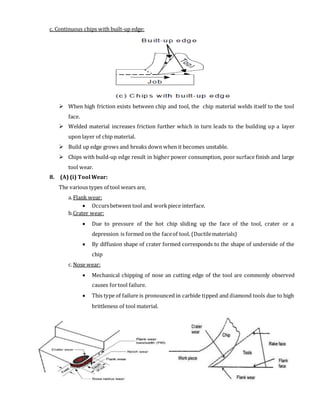
2. Factors that affect tool life such as rake angle, tool wear, and cutting fluids.
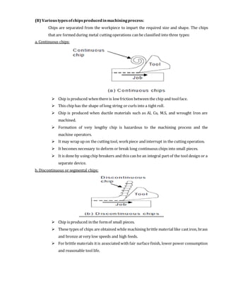
3. Different types of chips produced during machining such as continuous, discontinuous, and chips with built-up edge.
4. Tool materials used for different temperature ranges such as carbon steel, high-speed steel, cemented carbides, and ceramics.
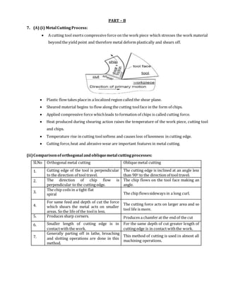
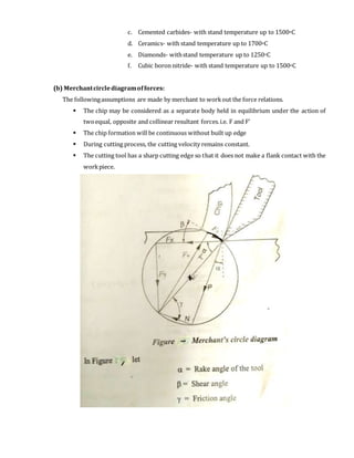
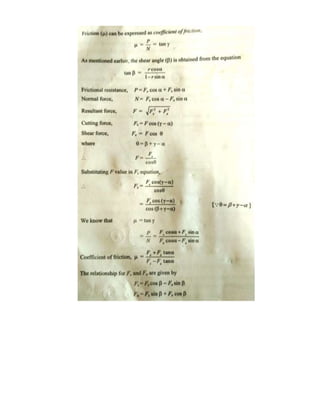
5. Merchant's circle diagram which models the forces during chip formation.