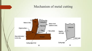
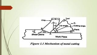
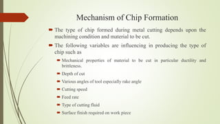
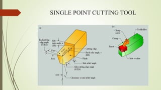
SlideShare a Scribd company logo
1 of 56
Download to read offline
UNIT 1
Theory of metal cutting
Mechanics of chip formation, single point cutting tool,
forces in machining, Types of chip, cutting tools –
nomenclature, orthogonal metal cutting, thermal aspects,
cutting tool materials, tool wear, tool life, surface finish,
cutting fluids and Machinability.
INTRODUCTION
 Components are made into various shapes and sizes by using metals.
 Depending the types of tools and operations.
 During the metal removal process, various forces act on the cutting
tool and work piece.
Metal Removing Process
 Non-cutting process (or) Chipless process
Forging, Drawing, Spinning, Rolling, Extruding
 Cutting process (or) Chip process
Turning, Drilling, Milling, Planer, Shaping
Mechanism of metal cutting
Mechanism of Chip Formation
 The type of chip formed during metal cutting depends upon the
machining condition and material to be cut.
 The following variables are influencing in producing the type of
chip such as
 Mechanical properties of material to be cut in particular ductility and
brittleness.
 Depth of cut
 Various angles of tool especially rake angle
 Cutting speed
 Feed rate
 Type of cutting fluid
 Surface finish required on work piece
SINGLE POINT CUTTING TOOL
Nomenclature of Single Point Cutting Tool
 Parts of a single point cutting tool
 Angles of single point cutting tool
 Effects of Back rake angle
 Effects of Side rake angle
Parts of a single point cutting tool
 Shank
 Face
 Flank
 Base
 Nose
 Cutting Edge
 Shank: Main body of tool, it is part of tool which is gripped in tool
holder
 Face: Top surface of tool b/w shank and point of tool. Chips flow
along this surface.
 Flank: Portion tool which faces the work. It is surface adjacent to &
below the cutting edge when tool lies in a horizontal position.
 Base: Bearing surface of tool on which it is held in a tool holder.
 Nose radius: Cutting tip, which carries a sharp cutting point. Nose
provided with radius to enable greater strength, increase tool life &
surface life.
 Cutting edge: It is the junction of face and flank.
Angles of single point cutting tool
 Rake angle
Back rake angle
Side rake angle
 Relief angle (or) clearance angle
End relief angle
Side relief angle
 Cutting edge angle
End cutting edge
Side cutting edge
 Nose radius
Effects of Back rake angle
 When will be the positive rake angle used?
To machine the work hardened materials
To machine low strength ferrous and non-ferrous metals
To turn the long shaft of smaller diameters
To machine the metal having lesser recommended cutting speeds
 When will be the negative rake angle used?
To machine high strength alloys
The feed rates are high
To give heavy and interrupted cuts
Effects of side rake angle
 During the cutting process, the amount of chip bend depends on side
rake angle.
Tool Signature
 Tool angles given in a definite pattern is called tool signature. The tool
angle have been standardized by the American Standards Association
(ASA).
 Back rake angle
 Side rake angle
 End relief angle
 Side relief angle
 End cutting edge angle
 Side cutting edge angle
 Nose radius
Types of chip formation
 Continuous chip
 Discontinuous chip
 Continuous chip with built-up edge
Continuous chip
 During cutting of ductile material, a continuous ribbon such as chip is
produced due to pressure of the tool cutting edge in compression and
shear.
 It gives the advantage of,
 Good surface finish
 Improving tool life
 Less power consumption
 However, the chip disposal is not easy and the surface finish of the
finished work get affected.
The following condition favors the formation
of continuous chips
 Ductile material such as low carbon steel, aluminum, copper etc.
 Smaller depth of cut
 High cutting speed
 Large rake angle
 Sharp cutting edge
 Proper cutting fluid
 Low friction between tool face and chip interface.
Discontinuous chip
 Discontinuous chip produced while machining brittle materials such as
grey cast iron, bronze, high carbon steel at low cutting speeds without
fluids.
 During machining the brittle material lacks its ductility which results
for plastic chip formation.
The following condition favors the formation
of discontinuous chips
 Machining of brittle material
 Small rake angle
 Higher depth of cut
 Low cutting speeds
 Excess cutting fluid
 Cutting ductile material at very low feeds with small rake angle of the
tool.
Continuous chip with built-up edge
 During the cutting process, the interface temperature and pressure are
quite high and also high fiction between tool-chip interface.
 It causes the chip material to weld itself to the tool face near the nose is
called “built-up edge”.
 This process gives the poor surface finish on the machined surface and
accelerated wears on the tool face.
The following condition favors the formation
of discontinuous chips with built-up edge.
 Low cutting speed
 Small rake angle
 Coarse feed
 Strong adhesion between chips and tool interface
 Insufficient cutting fluid
 Large uncut thickness
Types of metal cutting process
 Orthogonal cutting process (Two – dimensional cutting)
Cutting edge of the tool is perpendicular to the cutting velocity
vector.
 Oblique cutting process (Three dimensional cutting)
Cutting edge is inclined at an acute angle with the normal to the
cutting velocity vector.
Sl
No
Orthogonal cutting process Oblique cutting process
1 The chip flows over the tool face and
the direction of chip flow velocity is
normal to the cutting edge.
The chip flows on the tool face
making an angle with the normal
on the cutting edge.
2 The maximum chip thickness occurs
at its middle.
The maximum chip thickness may
not occur at the middle.
3 Tool is perfectly sharp and it contacts
the chip on rake face only.
Frequently, more than one cutting
edges are in action.
4 Tool life is less Tool life is more
Thermal aspects
The heat is generated in three region such as shear zone, chip tool
interface region and tool work interface region.
 Shear zone
 The zone which is affected by the energy required to shear the chip or to
separate the chip and work is called shear zone. The heat generation range
is 80-85%
 Chip - tool interface region
 The energy used to overcome the friction completely is the source of the
heat. The heat generation range is 15-20%
 Tool - work interface region
 The energy is supplied to overcome the rubbing friction between flank
face of the tool and work piece is the source of the heat. The heat
generation range is 1-3%
 The tool temperature increases due to the following factors such as
Cutting speed
Feed
Properties of tool materials etc.
TOOL WEAR
Attrition
Diffusion
Classification of tool wear
 Flank wear
 Feed < 0.15 mm/revolution
 Crater wear
 Nose wear
TOOL LIFE
 Tool life is defined as the cutting time required for reaching a tool life
criterion or time elapsed between two consecutive tool resharpening.
 The following are some of ways of expressing tool life.
Volume of metal removed per grind
Number of work pieces machined per grind
Time unit
Factors affecting tool life
 Cutting speed
 Feed and depth of cut
 Tool geometry
 Tool material
 Cutting fluid
 Work material
 Rigidity of work, tool and machine
Cutting speed
Feed and depth of cut
Tool geometry
SURFACE FINISH
 Generally, the surface finish of any product depends on the following
factors.
 Cutting speed
 Feed
 Depth of cut
CUTTING FLUIDS
 Cutting fluids are used to carry away the heat produced during the
machining. At the same time, it reduces the friction between tool and chip.
Functions of cutting fluids
 It prevents the work piece from excessive thermal distortion
 It improves the surface finish
 It causes the chips to break up into small parts. It protects the finished
surface from corrosion.
 It washes away the chip from the tool.
 It prevents the corrosion of work and machine.
Properties of cutting fluids
 It should have the high heat absorbing capacity
 It should be odourless
 It should be non-corrosive to work and tool
 It should have high flash point
 It should have low viscosity
 It should be economical to use
Types of cutting fluids
 Basically two main type of cutting fluids
 Water based cutting fluids
 Straight (or) heat oil based cutting fluids
Water based cutting fluids
 To improve the cooling and lubricating properties of water, the soft soap
or mineral oils are added to it. These oils are known as soluble oils.
Straight (or) heat oil based cutting fluids
 Straight oil based cutting fluids means pure oil based fluids. Most of the
oils are not directly used but it is mixed with other oils.
 It is classified into the following subgroups
 Mineral oils
 Straight fatty oils
 Mixed oils
 Sulphurised oils
 Chlorinated oils
Methods of applying cutting fluids
 Cutting fluids are used in many ways such as
 Drop by drop under gravity
 Flood under gravity
 Form of liquid jet
 Atomised form with compressed air
 Through centrifugal action
MACHINABILITY
 Machinability is defined as the ease with which a material can be
satisfactorily machined. It can also be defined as follows
 The life of tool before tool failure
 The quantity of the machined surface
 The power consumption per unit volume of material removed.
Variables affecting machinability
 Work variables
 Tool variables
 Machine variables
 Cutting conditions
Evaluation of machinability
 Tool life per grind
 Rate of metal removal per tool grind
 Surface finish
 Dimensional stability of the finished work
 Chip hardness
 Shape and size of chips
Advantages of high machinability
 Good surface finish can be produced
 Higher cutting speed can be used
 Less power consumption
 Metal removal rate is high
 Less tool wear
Machinability index
 Machinability index
I =
𝐶𝑢𝑡𝑡𝑖𝑛𝑔 𝑠𝑝𝑒𝑒𝑑 𝑜𝑓 𝑚𝑒𝑡𝑎𝑙 𝑖𝑛𝑣𝑒𝑠𝑡𝑖𝑔𝑎𝑡𝑒𝑑 𝑓𝑜𝑟 20 𝑚𝑖𝑛𝑢𝑡𝑒𝑠 𝑡𝑜𝑜𝑙 𝑙𝑖𝑓𝑒
𝐶𝑢𝑡𝑡𝑖𝑛𝑔 𝑠𝑝𝑒𝑒𝑑 𝑜𝑓 𝑠𝑡𝑎𝑛𝑑𝑎𝑟𝑑 𝑠𝑡𝑒𝑒𝑙 𝑓𝑜𝑟 20 𝑚𝑖𝑛𝑢𝑡𝑒𝑠 𝑡𝑜𝑜𝑙 𝑙𝑖𝑓𝑒
I =
𝑉𝑖
𝑉𝑠
 The machinability index for some common materials is given by
 Low carbon steel - 55 - 60%
 Stainless steel - 25%
 Aluminium alloy - 390 - 1500%
SHEAR STRAIN
MANUFACTURING PROCESS-II

More Related Content

What's hot

Manufacturing Engineering 2, cutting tools and tool holders
Manufacturing Engineering 2, cutting tools and tool holdersManufacturing Engineering 2, cutting tools and tool holders
Manufacturing Engineering 2, cutting tools and tool holdersGaurav Mistry
 
MANUFACTURING TECHNOLOGY-I UNIT 3
MANUFACTURING TECHNOLOGY-I UNIT 3MANUFACTURING TECHNOLOGY-I UNIT 3
MANUFACTURING TECHNOLOGY-I UNIT 3SIVASHANKAR N
 
Tool Wear and Tool life of single point cutting tool
Tool Wear and Tool life of single point cutting toolTool Wear and Tool life of single point cutting tool
Tool Wear and Tool life of single point cutting toolAkshay Arvind
 
Metal cutting additional
Metal cutting additionalMetal cutting additional
Metal cutting additionalNaman Dave
 
Factors affecting tool life in machining processes
Factors affecting tool life in machining processesFactors affecting tool life in machining processes
Factors affecting tool life in machining processesmohdalaamri
 
Chip formation
Chip formationChip formation
Chip formationFOS SOF
 
Unit 2 Machinability, Cutting Fluids, Tool Life & Wear, Tool Materials
Unit 2 Machinability, Cutting Fluids, Tool Life & Wear, Tool MaterialsUnit 2 Machinability, Cutting Fluids, Tool Life & Wear, Tool Materials
Unit 2 Machinability, Cutting Fluids, Tool Life & Wear, Tool MaterialsMechbytes
 
Tool wear
Tool wearTool wear
Tool wearcpandiv
 
4 types of chips (1)
4 types of chips (1)4 types of chips (1)
4 types of chips (1)Anit Aggarwal
 
Chips formed and its types in machining operations
Chips formed and its types in machining operationsChips formed and its types in machining operations
Chips formed and its types in machining operationsmohdsameer50
 
Theory of metal cutting
Theory of metal cuttingTheory of metal cutting
Theory of metal cuttingArul R
 
manufacturing process and their science
manufacturing process and their sciencemanufacturing process and their science
manufacturing process and their scienceJOSE BABU
 
Metal forming process, Non chip forming machining process
Metal forming process, Non chip forming machining processMetal forming process, Non chip forming machining process
Metal forming process, Non chip forming machining processSuyog Lokhande
 
Metal cutting 1
Metal cutting 1Metal cutting 1
Metal cutting 1Naman Dave
 

What's hot (20)

Manufacturing Engineering 2, cutting tools and tool holders
Manufacturing Engineering 2, cutting tools and tool holdersManufacturing Engineering 2, cutting tools and tool holders
Manufacturing Engineering 2, cutting tools and tool holders
 
MANUFACTURING TECHNOLOGY-I UNIT 3
MANUFACTURING TECHNOLOGY-I UNIT 3MANUFACTURING TECHNOLOGY-I UNIT 3
MANUFACTURING TECHNOLOGY-I UNIT 3
 
Metal cutting
Metal cuttingMetal cutting
Metal cutting
 
Tool Wear and Tool life of single point cutting tool
Tool Wear and Tool life of single point cutting toolTool Wear and Tool life of single point cutting tool
Tool Wear and Tool life of single point cutting tool
 
Metal cutting additional
Metal cutting additionalMetal cutting additional
Metal cutting additional
 
Factors affecting tool life in machining processes
Factors affecting tool life in machining processesFactors affecting tool life in machining processes
Factors affecting tool life in machining processes
 
Chips formation
Chips formationChips formation
Chips formation
 
Chip formation
Chip formationChip formation
Chip formation
 
Unit 2 Machinability, Cutting Fluids, Tool Life & Wear, Tool Materials
Unit 2 Machinability, Cutting Fluids, Tool Life & Wear, Tool MaterialsUnit 2 Machinability, Cutting Fluids, Tool Life & Wear, Tool Materials
Unit 2 Machinability, Cutting Fluids, Tool Life & Wear, Tool Materials
 
Me8451 qb2
Me8451 qb2Me8451 qb2
Me8451 qb2
 
Tool wear
Tool wearTool wear
Tool wear
 
4 types of chips (1)
4 types of chips (1)4 types of chips (1)
4 types of chips (1)
 
Chips formed and its types in machining operations
Chips formed and its types in machining operationsChips formed and its types in machining operations
Chips formed and its types in machining operations
 
Theory of metal cutting
Theory of metal cuttingTheory of metal cutting
Theory of metal cutting
 
manufacturing process and their science
manufacturing process and their sciencemanufacturing process and their science
manufacturing process and their science
 
CHIP FORMATION
CHIP FORMATIONCHIP FORMATION
CHIP FORMATION
 
Metal forming process, Non chip forming machining process
Metal forming process, Non chip forming machining processMetal forming process, Non chip forming machining process
Metal forming process, Non chip forming machining process
 
Tool Wear and Tool Life
Tool Wear and Tool Life Tool Wear and Tool Life
Tool Wear and Tool Life
 
Metal cutting 1
Metal cutting 1Metal cutting 1
Metal cutting 1
 
Cutting tools
Cutting tools Cutting tools
Cutting tools
 

Similar to MANUFACTURING PROCESS-II

Unit test 1 - mt-ii -answer key
Unit test 1 - mt-ii -answer keyUnit test 1 - mt-ii -answer key
Unit test 1 - mt-ii -answer keymohanraj r
 
Mechanics of Chip Formation - Unit of MFT
Mechanics of Chip Formation - Unit of MFTMechanics of Chip Formation - Unit of MFT
Mechanics of Chip Formation - Unit of MFThodmech61
 
04metalcutting1 161019143042
04metalcutting1 16101914304204metalcutting1 161019143042
04metalcutting1 161019143042manojkumarg1990
 
04 types of chip formation, cutting temperature,etc.,
04 types of chip formation, cutting temperature,etc.,04 types of chip formation, cutting temperature,etc.,
04 types of chip formation, cutting temperature,etc.,M Siva Kumar
 
Machining Technology-Turning
Machining Technology-TurningMachining Technology-Turning
Machining Technology-TurningManikandanSettu
 
MT-II UNIT I THEORY OF METAL CUTTING
MT-II UNIT I THEORY OF METAL CUTTINGMT-II UNIT I THEORY OF METAL CUTTING
MT-II UNIT I THEORY OF METAL CUTTINGKarthik R
 
Possible Interview Questions/Contents From Manufacturing Technology II
Possible Interview Questions/Contents  From  Manufacturing Technology IIPossible Interview Questions/Contents  From  Manufacturing Technology II
Possible Interview Questions/Contents From Manufacturing Technology IIDr. Ramesh B
 
THEORY OF METAL CUTTING.ppt
THEORY OF METAL CUTTING.pptTHEORY OF METAL CUTTING.ppt
THEORY OF METAL CUTTING.pptDineshKumar4165
 
Manufacturing Technology-II
Manufacturing Technology-II Manufacturing Technology-II
Manufacturing Technology-II nagoorvali8
 
Metal cutting manufacturing process part1
Metal cutting   manufacturing process part1Metal cutting   manufacturing process part1
Metal cutting manufacturing process part1Binit Kumar
 
Production engineering
Production engineeringProduction engineering
Production engineeringSTAY CURIOUS
 
Chip formation & cutting tool geometry
Chip formation & cutting tool geometryChip formation & cutting tool geometry
Chip formation & cutting tool geometryTarek Erin
 

Similar to MANUFACTURING PROCESS-II (20)

Unit test 1 - mt-ii -answer key
Unit test 1 - mt-ii -answer keyUnit test 1 - mt-ii -answer key
Unit test 1 - mt-ii -answer key
 
today2.pptx
 today2.pptx today2.pptx
today2.pptx
 
Mechanics of Chip Formation - Unit of MFT
Mechanics of Chip Formation - Unit of MFTMechanics of Chip Formation - Unit of MFT
Mechanics of Chip Formation - Unit of MFT
 
04 metal cutting(1)
04 metal cutting(1)04 metal cutting(1)
04 metal cutting(1)
 
04metalcutting1 161019143042
04metalcutting1 16101914304204metalcutting1 161019143042
04metalcutting1 161019143042
 
04 types of chip formation, cutting temperature,etc.,
04 types of chip formation, cutting temperature,etc.,04 types of chip formation, cutting temperature,etc.,
04 types of chip formation, cutting temperature,etc.,
 
Unit1
Unit1Unit1
Unit1
 
Machining Technology-Turning
Machining Technology-TurningMachining Technology-Turning
Machining Technology-Turning
 
Production technology Metal Cutting introduction
Production technology Metal Cutting introductionProduction technology Metal Cutting introduction
Production technology Metal Cutting introduction
 
Alagar.ppt
Alagar.pptAlagar.ppt
Alagar.ppt
 
MT-II UNIT I THEORY OF METAL CUTTING
MT-II UNIT I THEORY OF METAL CUTTINGMT-II UNIT I THEORY OF METAL CUTTING
MT-II UNIT I THEORY OF METAL CUTTING
 
Unit 1
Unit   1Unit   1
Unit 1
 
Possible Interview Questions/Contents From Manufacturing Technology II
Possible Interview Questions/Contents  From  Manufacturing Technology IIPossible Interview Questions/Contents  From  Manufacturing Technology II
Possible Interview Questions/Contents From Manufacturing Technology II
 
all.ppt
all.pptall.ppt
all.ppt
 
THEORY OF METAL CUTTING.ppt
THEORY OF METAL CUTTING.pptTHEORY OF METAL CUTTING.ppt
THEORY OF METAL CUTTING.ppt
 
Manufacturing Technology-II
Manufacturing Technology-II Manufacturing Technology-II
Manufacturing Technology-II
 
Machine shop theory
Machine shop theoryMachine shop theory
Machine shop theory
 
Metal cutting manufacturing process part1
Metal cutting   manufacturing process part1Metal cutting   manufacturing process part1
Metal cutting manufacturing process part1
 
Production engineering
Production engineeringProduction engineering
Production engineering
 
Chip formation & cutting tool geometry
Chip formation & cutting tool geometryChip formation & cutting tool geometry
Chip formation & cutting tool geometry
 

More from Dr.PERIASAMY K (20)

UNIT-III.ppt
UNIT-III.pptUNIT-III.ppt
UNIT-III.ppt
 
UNIT-II updated.ppt
UNIT-II updated.pptUNIT-II updated.ppt
UNIT-II updated.ppt
 
UNIT 1.ppt
UNIT 1.pptUNIT 1.ppt
UNIT 1.ppt
 
PPCE Unit-5.pptx
PPCE Unit-5.pptxPPCE Unit-5.pptx
PPCE Unit-5.pptx
 
PPCE Unit-4.pptx
PPCE Unit-4.pptxPPCE Unit-4.pptx
PPCE Unit-4.pptx
 
PPCE Unit-3.pptx
PPCE Unit-3.pptxPPCE Unit-3.pptx
PPCE Unit-3.pptx
 
PPCE Unit-2.pptx
PPCE Unit-2.pptxPPCE Unit-2.pptx
PPCE Unit-2.pptx
 
PPCE Unit -1.pptx
PPCE Unit -1.pptxPPCE Unit -1.pptx
PPCE Unit -1.pptx
 
POM UNIT-3.pptx
POM UNIT-3.pptxPOM UNIT-3.pptx
POM UNIT-3.pptx
 
POM UNIT-4.pptx
POM UNIT-4.pptxPOM UNIT-4.pptx
POM UNIT-4.pptx
 
Unit 5 Controlling.ppt
Unit 5 Controlling.pptUnit 5 Controlling.ppt
Unit 5 Controlling.ppt
 
POM UNIT-2.pptx
POM UNIT-2.pptxPOM UNIT-2.pptx
POM UNIT-2.pptx
 
POM UNIT-I.pdf
POM UNIT-I.pdfPOM UNIT-I.pdf
POM UNIT-I.pdf
 
MANUFACTURING PROCESS-II
MANUFACTURING PROCESS-IIMANUFACTURING PROCESS-II
MANUFACTURING PROCESS-II
 
MANUFACTURING PROCESS-II
MANUFACTURING PROCESS-IIMANUFACTURING PROCESS-II
MANUFACTURING PROCESS-II
 
MANUFACTURING PROCESS-I
MANUFACTURING PROCESS-IMANUFACTURING PROCESS-I
MANUFACTURING PROCESS-I
 
MANUFACTURING PROCESS-I
MANUFACTURING PROCESS-IMANUFACTURING PROCESS-I
MANUFACTURING PROCESS-I
 
MANUFACTURING PROCESS-I
MANUFACTURING PROCESS-IMANUFACTURING PROCESS-I
MANUFACTURING PROCESS-I
 
MANUFACTURING PROCESS-I
MANUFACTURING PROCESS-IMANUFACTURING PROCESS-I
MANUFACTURING PROCESS-I
 
MANUFACTURING PROCESS-I
MANUFACTURING PROCESS-IMANUFACTURING PROCESS-I
MANUFACTURING PROCESS-I
 

Recently uploaded

What are the advantages and disadvantages of membrane structures.pptx
What are the advantages and disadvantages of membrane structures.pptxWhat are the advantages and disadvantages of membrane structures.pptx
What are the advantages and disadvantages of membrane structures.pptxwendy cai
 
(ANVI) Koregaon Park Call Girls Just Call 7001035870 [ Cash on Delivery ] Pun...
(ANVI) Koregaon Park Call Girls Just Call 7001035870 [ Cash on Delivery ] Pun...(ANVI) Koregaon Park Call Girls Just Call 7001035870 [ Cash on Delivery ] Pun...
(ANVI) Koregaon Park Call Girls Just Call 7001035870 [ Cash on Delivery ] Pun...ranjana rawat
 
(PRIYA) Rajgurunagar Call Girls Just Call 7001035870 [ Cash on Delivery ] Pun...
(PRIYA) Rajgurunagar Call Girls Just Call 7001035870 [ Cash on Delivery ] Pun...(PRIYA) Rajgurunagar Call Girls Just Call 7001035870 [ Cash on Delivery ] Pun...
(PRIYA) Rajgurunagar Call Girls Just Call 7001035870 [ Cash on Delivery ] Pun...ranjana rawat
 
Call Girls Service Nagpur Tanvi Call 7001035870 Meet With Nagpur Escorts
Call Girls Service Nagpur Tanvi Call 7001035870 Meet With Nagpur EscortsCall Girls Service Nagpur Tanvi Call 7001035870 Meet With Nagpur Escorts
Call Girls Service Nagpur Tanvi Call 7001035870 Meet With Nagpur EscortsCall Girls in Nagpur High Profile
 
(MEERA) Dapodi Call Girls Just Call 7001035870 [ Cash on Delivery ] Pune Escorts
(MEERA) Dapodi Call Girls Just Call 7001035870 [ Cash on Delivery ] Pune Escorts(MEERA) Dapodi Call Girls Just Call 7001035870 [ Cash on Delivery ] Pune Escorts
(MEERA) Dapodi Call Girls Just Call 7001035870 [ Cash on Delivery ] Pune Escortsranjana rawat
 
Processing & Properties of Floor and Wall Tiles.pptx
Processing & Properties of Floor and Wall Tiles.pptxProcessing & Properties of Floor and Wall Tiles.pptx
Processing & Properties of Floor and Wall Tiles.pptxpranjaldaimarysona
 
Extrusion Processes and Their Limitations
Extrusion Processes and Their LimitationsExtrusion Processes and Their Limitations
Extrusion Processes and Their Limitations120cr0395
 
main PPT.pptx of girls hostel security using rfid
main PPT.pptx of girls hostel security using rfidmain PPT.pptx of girls hostel security using rfid
main PPT.pptx of girls hostel security using rfidNikhilNagaraju
 
Introduction to Multiple Access Protocol.pptx
Introduction to Multiple Access Protocol.pptxIntroduction to Multiple Access Protocol.pptx
Introduction to Multiple Access Protocol.pptxupamatechverse
 
Introduction and different types of Ethernet.pptx
Introduction and different types of Ethernet.pptxIntroduction and different types of Ethernet.pptx
Introduction and different types of Ethernet.pptxupamatechverse
 
VIP Call Girls Service Kondapur Hyderabad Call +91-8250192130
VIP Call Girls Service Kondapur Hyderabad Call +91-8250192130VIP Call Girls Service Kondapur Hyderabad Call +91-8250192130
VIP Call Girls Service Kondapur Hyderabad Call +91-8250192130Suhani Kapoor
 
(SHREYA) Chakan Call Girls Just Call 7001035870 [ Cash on Delivery ] Pune Esc...
(SHREYA) Chakan Call Girls Just Call 7001035870 [ Cash on Delivery ] Pune Esc...(SHREYA) Chakan Call Girls Just Call 7001035870 [ Cash on Delivery ] Pune Esc...
(SHREYA) Chakan Call Girls Just Call 7001035870 [ Cash on Delivery ] Pune Esc...ranjana rawat
 
chaitra-1.pptx fake news detection using machine learning
chaitra-1.pptx  fake news detection using machine learningchaitra-1.pptx  fake news detection using machine learning
chaitra-1.pptx fake news detection using machine learningmisbanausheenparvam
 
GDSC ASEB Gen AI study jams presentation
GDSC ASEB Gen AI study jams presentationGDSC ASEB Gen AI study jams presentation
GDSC ASEB Gen AI study jams presentationGDSCAESB
 
Analog to Digital and Digital to Analog Converter
Analog to Digital and Digital to Analog ConverterAnalog to Digital and Digital to Analog Converter
Analog to Digital and Digital to Analog ConverterAbhinavSharma374939
 

Recently uploaded (20)

What are the advantages and disadvantages of membrane structures.pptx
What are the advantages and disadvantages of membrane structures.pptxWhat are the advantages and disadvantages of membrane structures.pptx
What are the advantages and disadvantages of membrane structures.pptx
 
(ANVI) Koregaon Park Call Girls Just Call 7001035870 [ Cash on Delivery ] Pun...
(ANVI) Koregaon Park Call Girls Just Call 7001035870 [ Cash on Delivery ] Pun...(ANVI) Koregaon Park Call Girls Just Call 7001035870 [ Cash on Delivery ] Pun...
(ANVI) Koregaon Park Call Girls Just Call 7001035870 [ Cash on Delivery ] Pun...
 
(PRIYA) Rajgurunagar Call Girls Just Call 7001035870 [ Cash on Delivery ] Pun...
(PRIYA) Rajgurunagar Call Girls Just Call 7001035870 [ Cash on Delivery ] Pun...(PRIYA) Rajgurunagar Call Girls Just Call 7001035870 [ Cash on Delivery ] Pun...
(PRIYA) Rajgurunagar Call Girls Just Call 7001035870 [ Cash on Delivery ] Pun...
 
Call Girls Service Nagpur Tanvi Call 7001035870 Meet With Nagpur Escorts
Call Girls Service Nagpur Tanvi Call 7001035870 Meet With Nagpur EscortsCall Girls Service Nagpur Tanvi Call 7001035870 Meet With Nagpur Escorts
Call Girls Service Nagpur Tanvi Call 7001035870 Meet With Nagpur Escorts
 
(MEERA) Dapodi Call Girls Just Call 7001035870 [ Cash on Delivery ] Pune Escorts
(MEERA) Dapodi Call Girls Just Call 7001035870 [ Cash on Delivery ] Pune Escorts(MEERA) Dapodi Call Girls Just Call 7001035870 [ Cash on Delivery ] Pune Escorts
(MEERA) Dapodi Call Girls Just Call 7001035870 [ Cash on Delivery ] Pune Escorts
 
Processing & Properties of Floor and Wall Tiles.pptx
Processing & Properties of Floor and Wall Tiles.pptxProcessing & Properties of Floor and Wall Tiles.pptx
Processing & Properties of Floor and Wall Tiles.pptx
 
Call Us -/9953056974- Call Girls In Vikaspuri-/- Delhi NCR
Call Us -/9953056974- Call Girls In Vikaspuri-/- Delhi NCRCall Us -/9953056974- Call Girls In Vikaspuri-/- Delhi NCR
Call Us -/9953056974- Call Girls In Vikaspuri-/- Delhi NCR
 
Extrusion Processes and Their Limitations
Extrusion Processes and Their LimitationsExtrusion Processes and Their Limitations
Extrusion Processes and Their Limitations
 
main PPT.pptx of girls hostel security using rfid
main PPT.pptx of girls hostel security using rfidmain PPT.pptx of girls hostel security using rfid
main PPT.pptx of girls hostel security using rfid
 
9953056974 Call Girls In South Ex, Escorts (Delhi) NCR.pdf
9953056974 Call Girls In South Ex, Escorts (Delhi) NCR.pdf9953056974 Call Girls In South Ex, Escorts (Delhi) NCR.pdf
9953056974 Call Girls In South Ex, Escorts (Delhi) NCR.pdf
 
Introduction to Multiple Access Protocol.pptx
Introduction to Multiple Access Protocol.pptxIntroduction to Multiple Access Protocol.pptx
Introduction to Multiple Access Protocol.pptx
 
Introduction and different types of Ethernet.pptx
Introduction and different types of Ethernet.pptxIntroduction and different types of Ethernet.pptx
Introduction and different types of Ethernet.pptx
 
VIP Call Girls Service Kondapur Hyderabad Call +91-8250192130
VIP Call Girls Service Kondapur Hyderabad Call +91-8250192130VIP Call Girls Service Kondapur Hyderabad Call +91-8250192130
VIP Call Girls Service Kondapur Hyderabad Call +91-8250192130
 
(SHREYA) Chakan Call Girls Just Call 7001035870 [ Cash on Delivery ] Pune Esc...
(SHREYA) Chakan Call Girls Just Call 7001035870 [ Cash on Delivery ] Pune Esc...(SHREYA) Chakan Call Girls Just Call 7001035870 [ Cash on Delivery ] Pune Esc...
(SHREYA) Chakan Call Girls Just Call 7001035870 [ Cash on Delivery ] Pune Esc...
 
chaitra-1.pptx fake news detection using machine learning
chaitra-1.pptx  fake news detection using machine learningchaitra-1.pptx  fake news detection using machine learning
chaitra-1.pptx fake news detection using machine learning
 
DJARUM4D - SLOT GACOR ONLINE | SLOT DEMO ONLINE
DJARUM4D - SLOT GACOR ONLINE | SLOT DEMO ONLINEDJARUM4D - SLOT GACOR ONLINE | SLOT DEMO ONLINE
DJARUM4D - SLOT GACOR ONLINE | SLOT DEMO ONLINE
 
GDSC ASEB Gen AI study jams presentation
GDSC ASEB Gen AI study jams presentationGDSC ASEB Gen AI study jams presentation
GDSC ASEB Gen AI study jams presentation
 
Exploring_Network_Security_with_JA3_by_Rakesh Seal.pptx
Exploring_Network_Security_with_JA3_by_Rakesh Seal.pptxExploring_Network_Security_with_JA3_by_Rakesh Seal.pptx
Exploring_Network_Security_with_JA3_by_Rakesh Seal.pptx
 
★ CALL US 9953330565 ( HOT Young Call Girls In Badarpur delhi NCR
★ CALL US 9953330565 ( HOT Young Call Girls In Badarpur delhi NCR★ CALL US 9953330565 ( HOT Young Call Girls In Badarpur delhi NCR
★ CALL US 9953330565 ( HOT Young Call Girls In Badarpur delhi NCR
 
Analog to Digital and Digital to Analog Converter
Analog to Digital and Digital to Analog ConverterAnalog to Digital and Digital to Analog Converter
Analog to Digital and Digital to Analog Converter
 

MANUFACTURING PROCESS-II

  • 1. UNIT 1 Theory of metal cutting Mechanics of chip formation, single point cutting tool, forces in machining, Types of chip, cutting tools – nomenclature, orthogonal metal cutting, thermal aspects, cutting tool materials, tool wear, tool life, surface finish, cutting fluids and Machinability.
  • 2. INTRODUCTION  Components are made into various shapes and sizes by using metals.  Depending the types of tools and operations.  During the metal removal process, various forces act on the cutting tool and work piece.
  • 3. Metal Removing Process  Non-cutting process (or) Chipless process Forging, Drawing, Spinning, Rolling, Extruding  Cutting process (or) Chip process Turning, Drilling, Milling, Planer, Shaping
  • 5.
  • 6. Mechanism of Chip Formation  The type of chip formed during metal cutting depends upon the machining condition and material to be cut.  The following variables are influencing in producing the type of chip such as  Mechanical properties of material to be cut in particular ductility and brittleness.  Depth of cut  Various angles of tool especially rake angle  Cutting speed  Feed rate  Type of cutting fluid  Surface finish required on work piece
  • 8. Nomenclature of Single Point Cutting Tool  Parts of a single point cutting tool  Angles of single point cutting tool  Effects of Back rake angle  Effects of Side rake angle
  • 9. Parts of a single point cutting tool  Shank  Face  Flank  Base  Nose  Cutting Edge
  • 10.  Shank: Main body of tool, it is part of tool which is gripped in tool holder  Face: Top surface of tool b/w shank and point of tool. Chips flow along this surface.  Flank: Portion tool which faces the work. It is surface adjacent to & below the cutting edge when tool lies in a horizontal position.  Base: Bearing surface of tool on which it is held in a tool holder.  Nose radius: Cutting tip, which carries a sharp cutting point. Nose provided with radius to enable greater strength, increase tool life & surface life.  Cutting edge: It is the junction of face and flank.
  • 11. Angles of single point cutting tool  Rake angle Back rake angle Side rake angle  Relief angle (or) clearance angle End relief angle Side relief angle  Cutting edge angle End cutting edge Side cutting edge  Nose radius
  • 12. Effects of Back rake angle
  • 13.  When will be the positive rake angle used? To machine the work hardened materials To machine low strength ferrous and non-ferrous metals To turn the long shaft of smaller diameters To machine the metal having lesser recommended cutting speeds  When will be the negative rake angle used? To machine high strength alloys The feed rates are high To give heavy and interrupted cuts
  • 14. Effects of side rake angle  During the cutting process, the amount of chip bend depends on side rake angle.
  • 15. Tool Signature  Tool angles given in a definite pattern is called tool signature. The tool angle have been standardized by the American Standards Association (ASA).  Back rake angle  Side rake angle  End relief angle  Side relief angle  End cutting edge angle  Side cutting edge angle  Nose radius
  • 16. Types of chip formation  Continuous chip  Discontinuous chip  Continuous chip with built-up edge
  • 17. Continuous chip  During cutting of ductile material, a continuous ribbon such as chip is produced due to pressure of the tool cutting edge in compression and shear.  It gives the advantage of,  Good surface finish  Improving tool life  Less power consumption  However, the chip disposal is not easy and the surface finish of the finished work get affected.
  • 18.
  • 19. The following condition favors the formation of continuous chips  Ductile material such as low carbon steel, aluminum, copper etc.  Smaller depth of cut  High cutting speed  Large rake angle  Sharp cutting edge  Proper cutting fluid  Low friction between tool face and chip interface.
  • 20. Discontinuous chip  Discontinuous chip produced while machining brittle materials such as grey cast iron, bronze, high carbon steel at low cutting speeds without fluids.  During machining the brittle material lacks its ductility which results for plastic chip formation.
  • 21.
  • 22. The following condition favors the formation of discontinuous chips  Machining of brittle material  Small rake angle  Higher depth of cut  Low cutting speeds  Excess cutting fluid  Cutting ductile material at very low feeds with small rake angle of the tool.
  • 23. Continuous chip with built-up edge  During the cutting process, the interface temperature and pressure are quite high and also high fiction between tool-chip interface.  It causes the chip material to weld itself to the tool face near the nose is called “built-up edge”.  This process gives the poor surface finish on the machined surface and accelerated wears on the tool face.
  • 24.
  • 25. The following condition favors the formation of discontinuous chips with built-up edge.  Low cutting speed  Small rake angle  Coarse feed  Strong adhesion between chips and tool interface  Insufficient cutting fluid  Large uncut thickness
  • 26. Types of metal cutting process  Orthogonal cutting process (Two – dimensional cutting) Cutting edge of the tool is perpendicular to the cutting velocity vector.  Oblique cutting process (Three dimensional cutting) Cutting edge is inclined at an acute angle with the normal to the cutting velocity vector.
  • 27.
  • 28. Sl No Orthogonal cutting process Oblique cutting process 1 The chip flows over the tool face and the direction of chip flow velocity is normal to the cutting edge. The chip flows on the tool face making an angle with the normal on the cutting edge. 2 The maximum chip thickness occurs at its middle. The maximum chip thickness may not occur at the middle. 3 Tool is perfectly sharp and it contacts the chip on rake face only. Frequently, more than one cutting edges are in action. 4 Tool life is less Tool life is more
  • 29. Thermal aspects The heat is generated in three region such as shear zone, chip tool interface region and tool work interface region.  Shear zone  The zone which is affected by the energy required to shear the chip or to separate the chip and work is called shear zone. The heat generation range is 80-85%  Chip - tool interface region  The energy used to overcome the friction completely is the source of the heat. The heat generation range is 15-20%  Tool - work interface region  The energy is supplied to overcome the rubbing friction between flank face of the tool and work piece is the source of the heat. The heat generation range is 1-3%
  • 30.
  • 31.  The tool temperature increases due to the following factors such as Cutting speed Feed Properties of tool materials etc.
  • 34. Classification of tool wear  Flank wear  Feed < 0.15 mm/revolution  Crater wear  Nose wear
  • 35.
  • 36. TOOL LIFE  Tool life is defined as the cutting time required for reaching a tool life criterion or time elapsed between two consecutive tool resharpening.  The following are some of ways of expressing tool life. Volume of metal removed per grind Number of work pieces machined per grind Time unit
  • 37. Factors affecting tool life  Cutting speed  Feed and depth of cut  Tool geometry  Tool material  Cutting fluid  Work material  Rigidity of work, tool and machine
  • 39. Feed and depth of cut
  • 41. SURFACE FINISH  Generally, the surface finish of any product depends on the following factors.  Cutting speed  Feed  Depth of cut
  • 42. CUTTING FLUIDS  Cutting fluids are used to carry away the heat produced during the machining. At the same time, it reduces the friction between tool and chip.
  • 43. Functions of cutting fluids  It prevents the work piece from excessive thermal distortion  It improves the surface finish  It causes the chips to break up into small parts. It protects the finished surface from corrosion.  It washes away the chip from the tool.  It prevents the corrosion of work and machine.
  • 44. Properties of cutting fluids  It should have the high heat absorbing capacity  It should be odourless  It should be non-corrosive to work and tool  It should have high flash point  It should have low viscosity  It should be economical to use
  • 45. Types of cutting fluids  Basically two main type of cutting fluids  Water based cutting fluids  Straight (or) heat oil based cutting fluids
  • 46. Water based cutting fluids  To improve the cooling and lubricating properties of water, the soft soap or mineral oils are added to it. These oils are known as soluble oils.
  • 47. Straight (or) heat oil based cutting fluids  Straight oil based cutting fluids means pure oil based fluids. Most of the oils are not directly used but it is mixed with other oils.  It is classified into the following subgroups  Mineral oils  Straight fatty oils  Mixed oils  Sulphurised oils  Chlorinated oils
  • 48. Methods of applying cutting fluids  Cutting fluids are used in many ways such as  Drop by drop under gravity  Flood under gravity  Form of liquid jet  Atomised form with compressed air  Through centrifugal action
  • 49. MACHINABILITY  Machinability is defined as the ease with which a material can be satisfactorily machined. It can also be defined as follows  The life of tool before tool failure  The quantity of the machined surface  The power consumption per unit volume of material removed.
  • 50. Variables affecting machinability  Work variables  Tool variables  Machine variables  Cutting conditions
  • 51. Evaluation of machinability  Tool life per grind  Rate of metal removal per tool grind  Surface finish  Dimensional stability of the finished work  Chip hardness  Shape and size of chips
  • 52. Advantages of high machinability  Good surface finish can be produced  Higher cutting speed can be used  Less power consumption  Metal removal rate is high  Less tool wear
  • 53. Machinability index  Machinability index I = 𝐶𝑢𝑡𝑡𝑖𝑛𝑔 𝑠𝑝𝑒𝑒𝑑 𝑜𝑓 𝑚𝑒𝑡𝑎𝑙 𝑖𝑛𝑣𝑒𝑠𝑡𝑖𝑔𝑎𝑡𝑒𝑑 𝑓𝑜𝑟 20 𝑚𝑖𝑛𝑢𝑡𝑒𝑠 𝑡𝑜𝑜𝑙 𝑙𝑖𝑓𝑒 𝐶𝑢𝑡𝑡𝑖𝑛𝑔 𝑠𝑝𝑒𝑒𝑑 𝑜𝑓 𝑠𝑡𝑎𝑛𝑑𝑎𝑟𝑑 𝑠𝑡𝑒𝑒𝑙 𝑓𝑜𝑟 20 𝑚𝑖𝑛𝑢𝑡𝑒𝑠 𝑡𝑜𝑜𝑙 𝑙𝑖𝑓𝑒 I = 𝑉𝑖 𝑉𝑠  The machinability index for some common materials is given by  Low carbon steel - 55 - 60%  Stainless steel - 25%  Aluminium alloy - 390 - 1500%