Downloaded 183 times
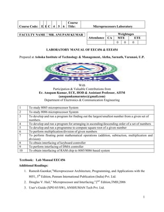


This document provides instructions and materials for experiments using 8085 and 8086 microprocessors. It includes 10 experiments such as developing programs to find the largest/smallest number, sort numbers, calculate square roots, and perform floating point math. It also covers interfacing the microprocessors to components like keyboards, RAM, and DMA controllers. The document lists the textbook, additional readings, faculty member, and assignments for the course.