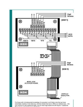
Interfaci
                                                                    ng to
                                                                     7-
                                                                  Segment
                                                                  Numeric
                                                                  Displays


7-Segment Numeric LED Displays

In industrial PLC applications, one of the old, but simpler methods of displaying numeric
information is to use one or more 7-Segment numeric displays connected to an output card
of a PLC... Although it is possible to build such a display yourself, it is far more common to
employ a pre-manufactured product such as the 4-digit panel mount unit shown at the top of
this page...

To correctly interface a PLC to such a display, it helps to first understand what basic
electronic components are typically employed in their makeup, and how this effects our task
of interfacing to, and programming such a unit... Although both LED and LCD numeric
displays are readily available, and interfaced similarly, we'll concentrate on the more
common LED units in the examples to follow...
BCD to 7-Segment Decoder c/w 4-bit Latch

Once 7-Segment LED displays became readily available, a simple IC known as a "BCD to 7-
Segment decoder" was quickly developed to simplify their use... Binary formatted data
presented to this IC's inputs results in the IC's outputs being placed into the correct state to
display the equivalent numeral (0 to 9) on a 7-Segment display...

Although BCD to 7-Segment decoder ICs are available without built in latches, this particular
IC includes a built in 4-bit latch which we will make use of in later examples... For now the
latch is set to simply allow input data to freely pass through to the decoder...
In the above diagram, the 4 toggle switches, SW0 to SW3 are used to select the desired
numeral (0-9) that will appear on the 7-Segment display... By using a decoder, it's now
simply a matter of setting the correct 4-bit BCD pattern feeding the inputs of the decoder,
and the decoder takes care of the rest...


                            BCD Input Data
                      SW3     SW2    SW1     SW0     Numeral Displayed
                        0      0       0       0              0
                        0      0       0       1              1
0       0       1       0              2
                        0       0       1       1              3
                        0       1       0       0              4
                        0       1       0       1              5
                        0       1       1       0              6
                        0       1       1       1              7
                        1       0       0       0              8
                        1       0       0       1              9


The decoder section also has two additional inputs... Lamp Test (LT) turns all segments on
so you can verify at once that all display segments are working, or identify display units that
need to be replaced... This input is normally left at logic 1... The Blanking (BL) input is just
the reverse; it forces the entire display off... This is used in many cases to blank out leading
or trailing zeros from a long display... LT will override BL so you can test even blanked-out
display digits...

One should also note that the same circuit could conceivably be controlled by a PLC, if 4
output bits from a 5VDC PLC output card were used in place of the 4 switches shown... If an
8-bit output card were available, then two such circuits (2 digits) could be controlled... A 16-
bit card would in turn allow us to control four such circuits (4 digits)..etc...


Parallel Non-Multiplexed Multiple Digit Display
The figure (above) on the left is taken from the LogixPro I/O simulator screen, and depicts a
common method of interfacing to a 4 digit display... The figures on the right are taken from
the data sheet of a pre-manufactured 4 digit display unit which could be readily employed in
this particular application...

The manufactured unit does contain four separate circuits, and each circuit (digit) has it's
own decoder, but compared to our earlier circuit example, this unit employs additional
components and circuitry making it far more versatile and easy to use...

Note that there are 4 "Strobe" lines shown; one for each digit... These strobe lines control
built in IC latches which provide us with the option of multiplexing the digits, or displays, if
we wished to do so... In the above non-multiplexed application, the strobes are permanently
enabled allowing data to simply pass through from the BCD inputs and be displayed as
normal...

Also note that this particular unit is designed for 24VDC use... This is by far the most
common DC voltage level used in industrial installations, and PLC I/O cards designed for
such use are therefore extremely common... In comparison to 5VDC circuits, 24VDC circuits
can typically tolerate far greater supply voltage excursions, are less sensitive to the effects
of contact resistance, and more tolerant of electrically noisy environments...


Multiplexed Digits

By making use of the 4-bit latches that are built into the 4511 IC, we can easily multiplex the
digits if so desired... By properly controlling the state of each latch enable pin (LE) we can
use the same input data lines (4 switches) to selectively write to each 7-Segment display
independently... With just a minor modification to our circuit, we will be able to essentially
treat each digit as a unique 4-bit memory location where BCD data of our choosing can be
stored and retained...
In the above schematic diagram, each display may be written to separately... First the BCD
equivalent of the desired numeral (0-9) is set using the 4 data switches... If SW1 is then
closed, the current BCD input data will enter the latch of the upper 4511 IC, and will be
passed on to the decoder causing the numeral to displayed... if SW1 is then opened, the
latch will retain the current data, but will now ignore any changes on it's inputs... The desired
numeral will continue to be displayed by the upper LED display until power is lost, or SW1 is
again closed and new data is allowed to enter it's latch...

The Lower 7-Segment display may be written to in a similar fashion... Set the BCD
equivalent of the desired digit using the 4 data switches, then close SW2 momentarily to
store and retain the current BCD data... We might say that we are strobing the data into the
display...

We could readily replace the 4 data switches and 2 latch switches if we had 6 5VDC outputs
available on our PLC... If we wished to add additional digits, we would require 1 more PLC
output for each digit added... By multiplexing the data in this fashion we would only require 8
PLC outputs to control a 4 digit display...


4 Digit Display configured for Multiplexed Digits


By using multiplexed data lines as shown above, we can dramatically reduce the number of
PLC outputs required (8) to control this 4 digit display... The down side is that writing a
ladder logic program to update a display wired in this fashion will be somewhat more
complicated then one written to control 4 digits wired in parallel...

If you have been looking closely, you may have questioned the purpose of the dual inline
sockets located on the wiring PCB of this manufactured display unit.. Well essentially the 16
data lines are internally connected in parallel with these sockets, and this allows us to easily
add additional units by simply interconnecting them using a flat ribbon cable assembly...
Multiple 4 Digit Displays configured for Multiplexed Digits
For those with a fundamental knowledge of computers, you'll likely note that we have
essentially created a 4-bit data bus, and the strobe lines are in effect our address bus... We
can continue to add additional digits, and for each digit added we will require 1 additional
Interfacing to

Interfacing to

  • 1.
    Interfaci ng to 7- Segment Numeric Displays 7-Segment Numeric LED Displays In industrial PLC applications, one of the old, but simpler methods of displaying numeric information is to use one or more 7-Segment numeric displays connected to an output card of a PLC... Although it is possible to build such a display yourself, it is far more common to employ a pre-manufactured product such as the 4-digit panel mount unit shown at the top of this page... To correctly interface a PLC to such a display, it helps to first understand what basic electronic components are typically employed in their makeup, and how this effects our task of interfacing to, and programming such a unit... Although both LED and LCD numeric displays are readily available, and interfaced similarly, we'll concentrate on the more common LED units in the examples to follow...
  • 2.
    BCD to 7-SegmentDecoder c/w 4-bit Latch Once 7-Segment LED displays became readily available, a simple IC known as a "BCD to 7- Segment decoder" was quickly developed to simplify their use... Binary formatted data presented to this IC's inputs results in the IC's outputs being placed into the correct state to display the equivalent numeral (0 to 9) on a 7-Segment display... Although BCD to 7-Segment decoder ICs are available without built in latches, this particular IC includes a built in 4-bit latch which we will make use of in later examples... For now the latch is set to simply allow input data to freely pass through to the decoder...
  • 3.
    In the abovediagram, the 4 toggle switches, SW0 to SW3 are used to select the desired numeral (0-9) that will appear on the 7-Segment display... By using a decoder, it's now simply a matter of setting the correct 4-bit BCD pattern feeding the inputs of the decoder, and the decoder takes care of the rest... BCD Input Data SW3 SW2 SW1 SW0 Numeral Displayed 0 0 0 0 0 0 0 0 1 1
  • 4.
    0 0 1 0 2 0 0 1 1 3 0 1 0 0 4 0 1 0 1 5 0 1 1 0 6 0 1 1 1 7 1 0 0 0 8 1 0 0 1 9 The decoder section also has two additional inputs... Lamp Test (LT) turns all segments on so you can verify at once that all display segments are working, or identify display units that need to be replaced... This input is normally left at logic 1... The Blanking (BL) input is just the reverse; it forces the entire display off... This is used in many cases to blank out leading or trailing zeros from a long display... LT will override BL so you can test even blanked-out display digits... One should also note that the same circuit could conceivably be controlled by a PLC, if 4 output bits from a 5VDC PLC output card were used in place of the 4 switches shown... If an 8-bit output card were available, then two such circuits (2 digits) could be controlled... A 16- bit card would in turn allow us to control four such circuits (4 digits)..etc... Parallel Non-Multiplexed Multiple Digit Display
  • 5.
    The figure (above)on the left is taken from the LogixPro I/O simulator screen, and depicts a common method of interfacing to a 4 digit display... The figures on the right are taken from the data sheet of a pre-manufactured 4 digit display unit which could be readily employed in this particular application... The manufactured unit does contain four separate circuits, and each circuit (digit) has it's own decoder, but compared to our earlier circuit example, this unit employs additional components and circuitry making it far more versatile and easy to use... Note that there are 4 "Strobe" lines shown; one for each digit... These strobe lines control built in IC latches which provide us with the option of multiplexing the digits, or displays, if we wished to do so... In the above non-multiplexed application, the strobes are permanently enabled allowing data to simply pass through from the BCD inputs and be displayed as normal... Also note that this particular unit is designed for 24VDC use... This is by far the most common DC voltage level used in industrial installations, and PLC I/O cards designed for such use are therefore extremely common... In comparison to 5VDC circuits, 24VDC circuits can typically tolerate far greater supply voltage excursions, are less sensitive to the effects
  • 6.
    of contact resistance,and more tolerant of electrically noisy environments... Multiplexed Digits By making use of the 4-bit latches that are built into the 4511 IC, we can easily multiplex the digits if so desired... By properly controlling the state of each latch enable pin (LE) we can use the same input data lines (4 switches) to selectively write to each 7-Segment display independently... With just a minor modification to our circuit, we will be able to essentially treat each digit as a unique 4-bit memory location where BCD data of our choosing can be stored and retained...
  • 7.
    In the aboveschematic diagram, each display may be written to separately... First the BCD equivalent of the desired numeral (0-9) is set using the 4 data switches... If SW1 is then closed, the current BCD input data will enter the latch of the upper 4511 IC, and will be passed on to the decoder causing the numeral to displayed... if SW1 is then opened, the latch will retain the current data, but will now ignore any changes on it's inputs... The desired numeral will continue to be displayed by the upper LED display until power is lost, or SW1 is again closed and new data is allowed to enter it's latch... The Lower 7-Segment display may be written to in a similar fashion... Set the BCD equivalent of the desired digit using the 4 data switches, then close SW2 momentarily to store and retain the current BCD data... We might say that we are strobing the data into the
  • 8.
    display... We could readilyreplace the 4 data switches and 2 latch switches if we had 6 5VDC outputs available on our PLC... If we wished to add additional digits, we would require 1 more PLC output for each digit added... By multiplexing the data in this fashion we would only require 8 PLC outputs to control a 4 digit display... 4 Digit Display configured for Multiplexed Digits By using multiplexed data lines as shown above, we can dramatically reduce the number of PLC outputs required (8) to control this 4 digit display... The down side is that writing a ladder logic program to update a display wired in this fashion will be somewhat more complicated then one written to control 4 digits wired in parallel... If you have been looking closely, you may have questioned the purpose of the dual inline sockets located on the wiring PCB of this manufactured display unit.. Well essentially the 16 data lines are internally connected in parallel with these sockets, and this allows us to easily add additional units by simply interconnecting them using a flat ribbon cable assembly...
  • 9.
    Multiple 4 DigitDisplays configured for Multiplexed Digits
  • 10.
    For those witha fundamental knowledge of computers, you'll likely note that we have essentially created a 4-bit data bus, and the strobe lines are in effect our address bus... We can continue to add additional digits, and for each digit added we will require 1 additional