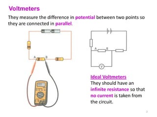
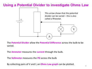
1) Voltmeters are connected in parallel to measure potential difference without drawing current from the circuit. Ideal voltmeters have infinite resistance.
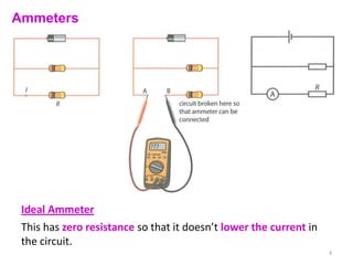
2) Ammeters are connected in series to measure current, with ideal ammeters having zero resistance to avoid lowering the circuit current.
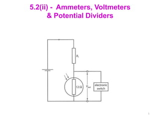
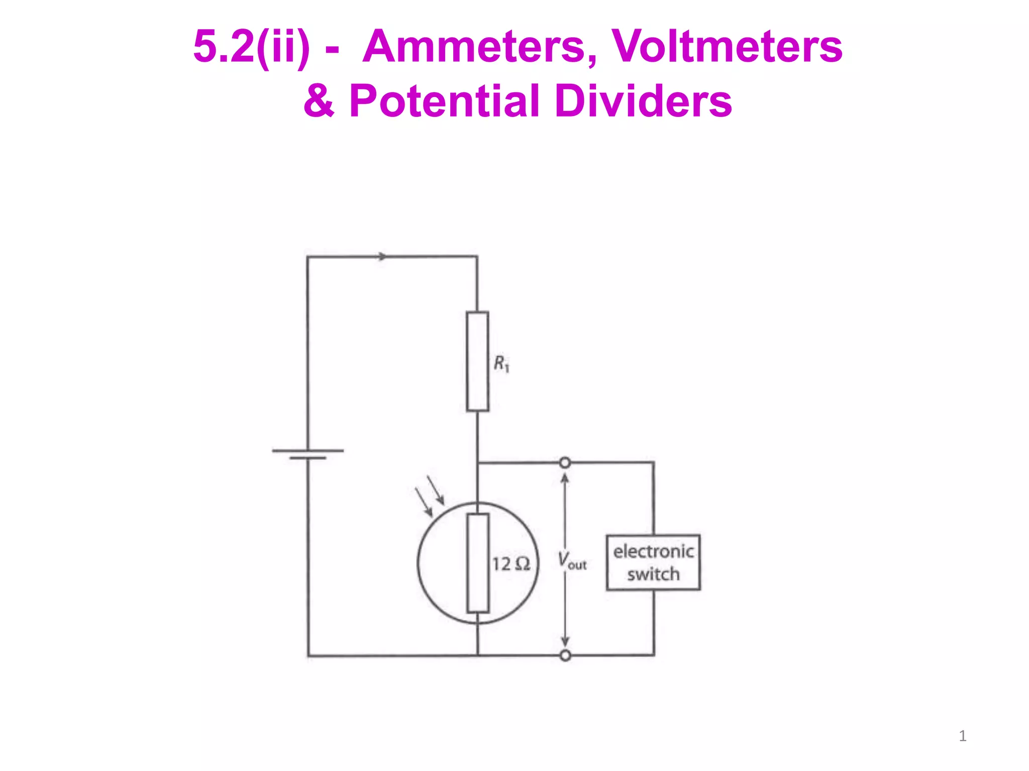
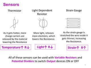
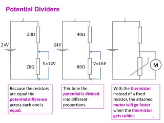
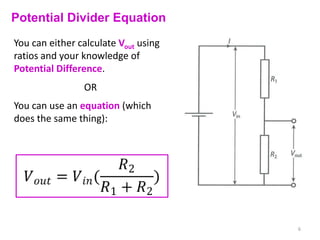
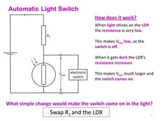
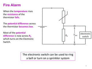
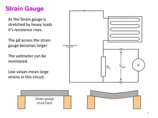
3) Potential dividers use two resistors connected in series to provide variable output voltages. They can be used with sensors like thermistors and light dependent resistors to control output devices.