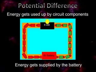
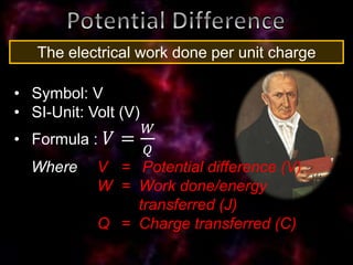
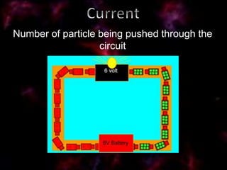
Power source
To supply
electrical power
Conductor
To conduct
electricity
A device that
uses energy
A switch that controls the flow of
electricity is a good addition
Cell
Battery
Light Bulb
Resistor
Switch
Ammeter Voltmeter
𝒆−
Electrons are
supplied at the
negative pole of
the battery
Flow from
negative to
positive
Electrical current is the flow of electrons
Historically it was
thought electricity
was the flow of +
charges
Flow from positive to negative
We still use the
convention today
Energy gets supplied by the battery
Energy gets used up by circuit components
• Symbol: V
• SI-Unit: Volt (V)
• Formula : 𝑉 =
𝑊
𝑄
Where V = Potential difference (V)
W = Work done/energy
transferred (J)
Q = Charge transferred (C)
The electrical work done per unit charge
Measured with:
Voltmeter
Electromotor Force:
The maximum amount of electrical energy that
a battery can supply to the charge that flows
through it
V
Measured across the poles of the battery when
switch is open (no current)
10 J energy is transferred when 5
Coulomb charge moves from point A to
point B. Calculate the potential difference
between the two points.
Number of particle being pushed through the
circuit
The rate at which charge flows
• Symbol: I
• SI-Unit: Ampère (A)
• Formula : 𝐼 =
𝑄
∆𝑡
Where I = Current (A)
Δt = Time (s)
Q = Charge transferred (C)
1 Ampère is the current when 1 Coulomb
charge moves past a point in 1 second
Measured with:
Ammeter
It takes 5 C charge 2 min to move from
point A to point B. Calculate the current
in the wire.
Calculate the current if 10 J energy is
converted to heat by a lightbulb in 50 s.
The potential difference over the ends of
the lightbulb is 5 V.
Magnified representation of a wire
+
+
+
+
+
+
+ +
+ +
+
+
+
+ +
+
+
+
+
+
+ +
+
+
+
+
+
• Delocalized electrons collides wit positive
atomic rests
• Causes Resistance
Tendency to inhibit the flow of electrons
Resistance increases if temperature
increases
Resistance decreases if thickness
increases
Resistance increases if length increases
Different materials
does not conduct
electricity to the
same extent
The relationship of the potential difference (V)
across a component to the current (I) through
that component
• Symbol: R
• SI-Unit: Ohm (Ω)
• Formula : 𝑅 =
𝑉
𝐼
Where R = Resistance (Ω)
V = Potential difference (V)
I = Current (A)
A conductor has a resistance of 1 Ω if a current
of 1 A flows through it while the potential
difference across the ends of the conductor is
1 V
V
I R
The ammeter
reading is 2 A
and the
Voltmeter
reading is 10 V.
a) Calculate the resistance R.
b) What is the emf of the battery?
Resistors in series act as voltage dividers
while the current stays the same
𝑉𝑇 = 𝑉1 + 𝑉2
Advantage:
Lowers electricity usage
𝑅 𝑇 = 𝑅1 + 𝑅2 + 𝑅3
𝑉𝑇 = 𝑉1 + 𝑉2 + 𝑉3
𝐼 𝑇 = 𝐼1 = 𝐼2
V
I R
Each cell has an emf of 10
V. The resistors have the
following resistances:
R1= 3 Ω; R2 = 2 Ω; R3 = 5 Ω
Calculate:
a) The total
voltage
b) Total
resistance
c) Ammeter
Reading
d) The readings
on each of
the
voltmeters
Resistors in parallel act as current dividers
while the voltage stays the same
Advantage:
If one lightbulb fuses the other will still work
1
𝑅 𝑇
=
1
𝑅1
+
1
𝑅2
+
1
𝑅3
𝑉𝑇 = 𝑉1 = 𝑉2 = 𝑉3
𝐼 𝑇 = 𝐼1 + 𝐼2 + 𝐼3
V
I R
Each cell has an emf of
1,5 V. The ammeter
readings are as follows:
A1= 1 A; A2 = 2 A
Calculate:
a) The total voltage
b) Total resistance
c) The readings on
each of the
voltmeters
d) Each of the
resistances
Resistor in series with parallel connection
1
𝑅 𝑃
=
1
𝑅2
+
1
𝑅3
𝑉𝑇 = 𝑉1 + 𝑉𝑃
Calculate Rp
𝑉𝑃 = 𝑉2 = 𝑉3
𝑅 𝑇 = 𝑅1 + 𝑅 𝑃
Calculate RT
Resistor in parallel with series connection
1
𝑅 𝑇
=
1
𝑅 𝑠
+
1
𝑅3
𝑉𝑠 = 𝑉1 + 𝑉2
Calculate Rs
𝑉𝑇 = 𝑉𝑠 = 𝑉3
𝑅 𝑠 = 𝑅1 + 𝑅2
Calculate RT
The potential difference across R1 is 10 V and
the reading on A1 is 0,4 A. The resistances of
R2 and R3 is 45 Ω and 157,5 Ω respectively.
a) What is the reading on V1 if switch S2 is
open?
b) What is the potential difference over the
battery if switch S2 is open?
Both switches are now closed.
c) Calculate the resistance of R1.
d) Calculate the total resistance.
e) What is the reading of V1?
f) What is the readings on A2 and A3?
g) What is the current through R3?
The switch S2 is now open.
h) What is the new readings on A1 and V1?
i) How did the voltage across resistor R1
change? Explain why
V1
R1 R2
R3
V2
V3
Vs
V1
R1
R2
R3
V2
V3
VT
I1
I2
I3
IT
A
V
R
V1
R1 R2
R3
V2 V3
VT
I1 I2
IT IT
A1
R1
R2
R3
A2
A3
S1
V1
S2
24 V

Current electricity

  • 2.
    Power source To supply electricalpower Conductor To conduct electricity A device that uses energy A switch that controls the flow of electricity is a good addition
  • 3.
  • 4.
  • 5.
    𝒆− Electrons are supplied atthe negative pole of the battery Flow from negative to positive Electrical current is the flow of electrons
  • 6.
    Historically it was thoughtelectricity was the flow of + charges Flow from positive to negative We still use the convention today
  • 8.
    Energy gets suppliedby the battery Energy gets used up by circuit components
  • 9.
    • Symbol: V •SI-Unit: Volt (V) • Formula : 𝑉 = 𝑊 𝑄 Where V = Potential difference (V) W = Work done/energy transferred (J) Q = Charge transferred (C) The electrical work done per unit charge
  • 10.
  • 11.
    Electromotor Force: The maximumamount of electrical energy that a battery can supply to the charge that flows through it
  • 12.
    V Measured across thepoles of the battery when switch is open (no current)
  • 13.
    10 J energyis transferred when 5 Coulomb charge moves from point A to point B. Calculate the potential difference between the two points.
  • 15.
    Number of particlebeing pushed through the circuit
  • 16.
    The rate atwhich charge flows • Symbol: I • SI-Unit: Ampère (A) • Formula : 𝐼 = 𝑄 ∆𝑡 Where I = Current (A) Δt = Time (s) Q = Charge transferred (C) 1 Ampère is the current when 1 Coulomb charge moves past a point in 1 second
  • 17.
  • 18.
    It takes 5C charge 2 min to move from point A to point B. Calculate the current in the wire. Calculate the current if 10 J energy is converted to heat by a lightbulb in 50 s. The potential difference over the ends of the lightbulb is 5 V.
  • 19.
    Magnified representation ofa wire + + + + + + + + + + + + + + + + + + + + + + + + + + + • Delocalized electrons collides wit positive atomic rests • Causes Resistance Tendency to inhibit the flow of electrons
  • 20.
    Resistance increases iftemperature increases Resistance decreases if thickness increases
  • 21.
    Resistance increases iflength increases Different materials does not conduct electricity to the same extent
  • 22.
    The relationship ofthe potential difference (V) across a component to the current (I) through that component • Symbol: R • SI-Unit: Ohm (Ω) • Formula : 𝑅 = 𝑉 𝐼 Where R = Resistance (Ω) V = Potential difference (V) I = Current (A)
  • 23.
    A conductor hasa resistance of 1 Ω if a current of 1 A flows through it while the potential difference across the ends of the conductor is 1 V V I R
  • 24.
    The ammeter reading is2 A and the Voltmeter reading is 10 V. a) Calculate the resistance R. b) What is the emf of the battery?
  • 25.
    Resistors in seriesact as voltage dividers while the current stays the same 𝑉𝑇 = 𝑉1 + 𝑉2
  • 26.
  • 27.
    𝑅 𝑇 =𝑅1 + 𝑅2 + 𝑅3 𝑉𝑇 = 𝑉1 + 𝑉2 + 𝑉3 𝐼 𝑇 = 𝐼1 = 𝐼2 V I R
  • 28.
    Each cell hasan emf of 10 V. The resistors have the following resistances: R1= 3 Ω; R2 = 2 Ω; R3 = 5 Ω Calculate: a) The total voltage b) Total resistance c) Ammeter Reading d) The readings on each of the voltmeters
  • 29.
    Resistors in parallelact as current dividers while the voltage stays the same
  • 30.
    Advantage: If one lightbulbfuses the other will still work
  • 31.
    1 𝑅 𝑇 = 1 𝑅1 + 1 𝑅2 + 1 𝑅3 𝑉𝑇 =𝑉1 = 𝑉2 = 𝑉3 𝐼 𝑇 = 𝐼1 + 𝐼2 + 𝐼3 V I R
  • 32.
    Each cell hasan emf of 1,5 V. The ammeter readings are as follows: A1= 1 A; A2 = 2 A Calculate: a) The total voltage b) Total resistance c) The readings on each of the voltmeters d) Each of the resistances
  • 33.
    Resistor in serieswith parallel connection 1 𝑅 𝑃 = 1 𝑅2 + 1 𝑅3 𝑉𝑇 = 𝑉1 + 𝑉𝑃 Calculate Rp 𝑉𝑃 = 𝑉2 = 𝑉3 𝑅 𝑇 = 𝑅1 + 𝑅 𝑃 Calculate RT
  • 34.
    Resistor in parallelwith series connection 1 𝑅 𝑇 = 1 𝑅 𝑠 + 1 𝑅3 𝑉𝑠 = 𝑉1 + 𝑉2 Calculate Rs 𝑉𝑇 = 𝑉𝑠 = 𝑉3 𝑅 𝑠 = 𝑅1 + 𝑅2 Calculate RT
  • 36.
    The potential differenceacross R1 is 10 V and the reading on A1 is 0,4 A. The resistances of R2 and R3 is 45 Ω and 157,5 Ω respectively. a) What is the reading on V1 if switch S2 is open? b) What is the potential difference over the battery if switch S2 is open? Both switches are now closed. c) Calculate the resistance of R1.
  • 37.
    d) Calculate thetotal resistance. e) What is the reading of V1? f) What is the readings on A2 and A3? g) What is the current through R3? The switch S2 is now open. h) What is the new readings on A1 and V1? i) How did the voltage across resistor R1 change? Explain why
  • 38.
  • 39.
  • 40.
  • 41.
  • 42.