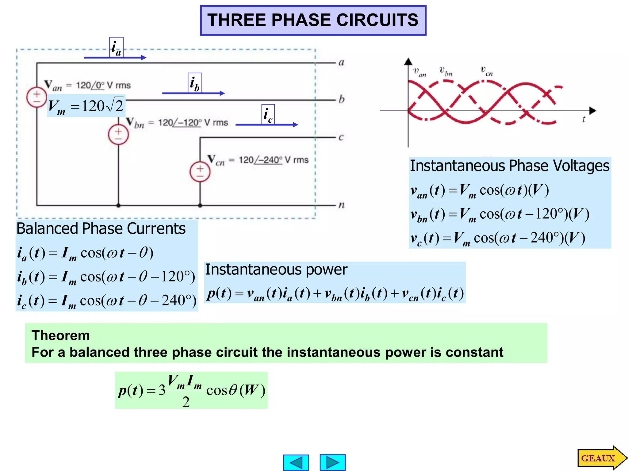
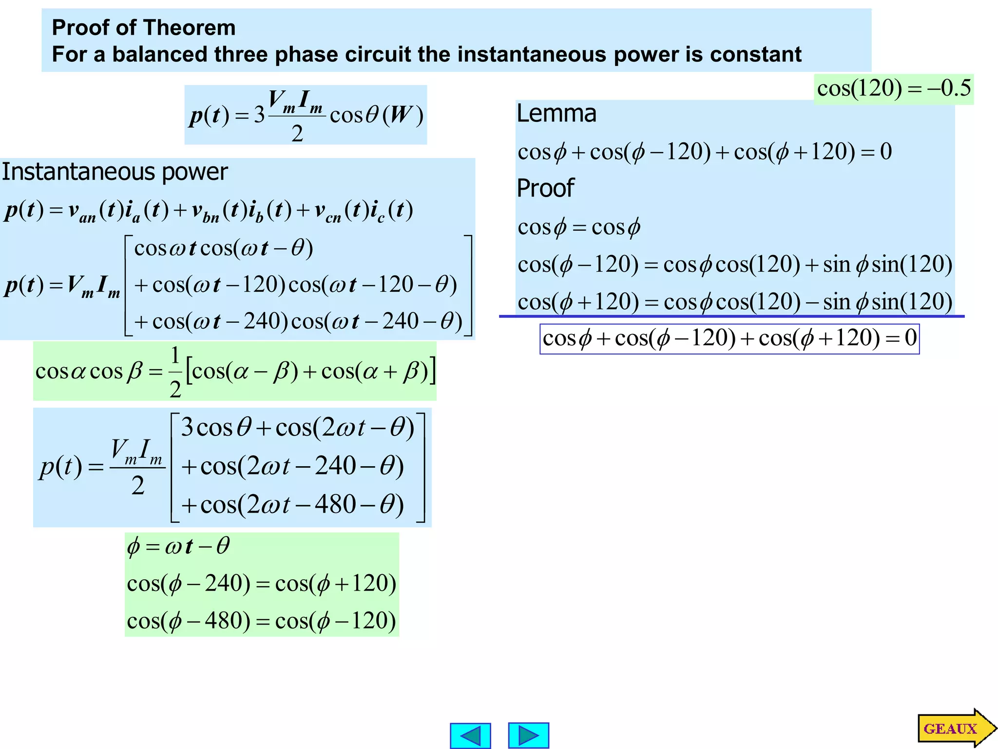
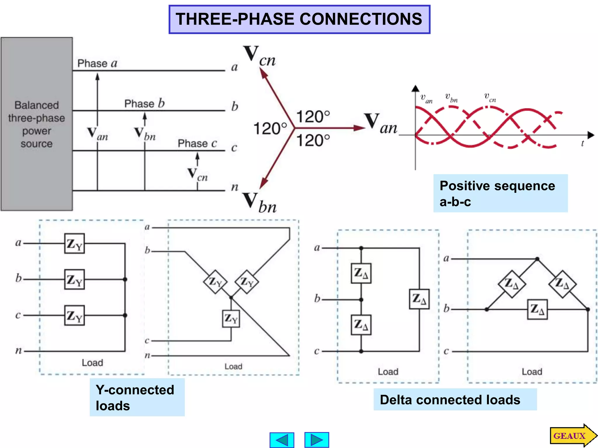
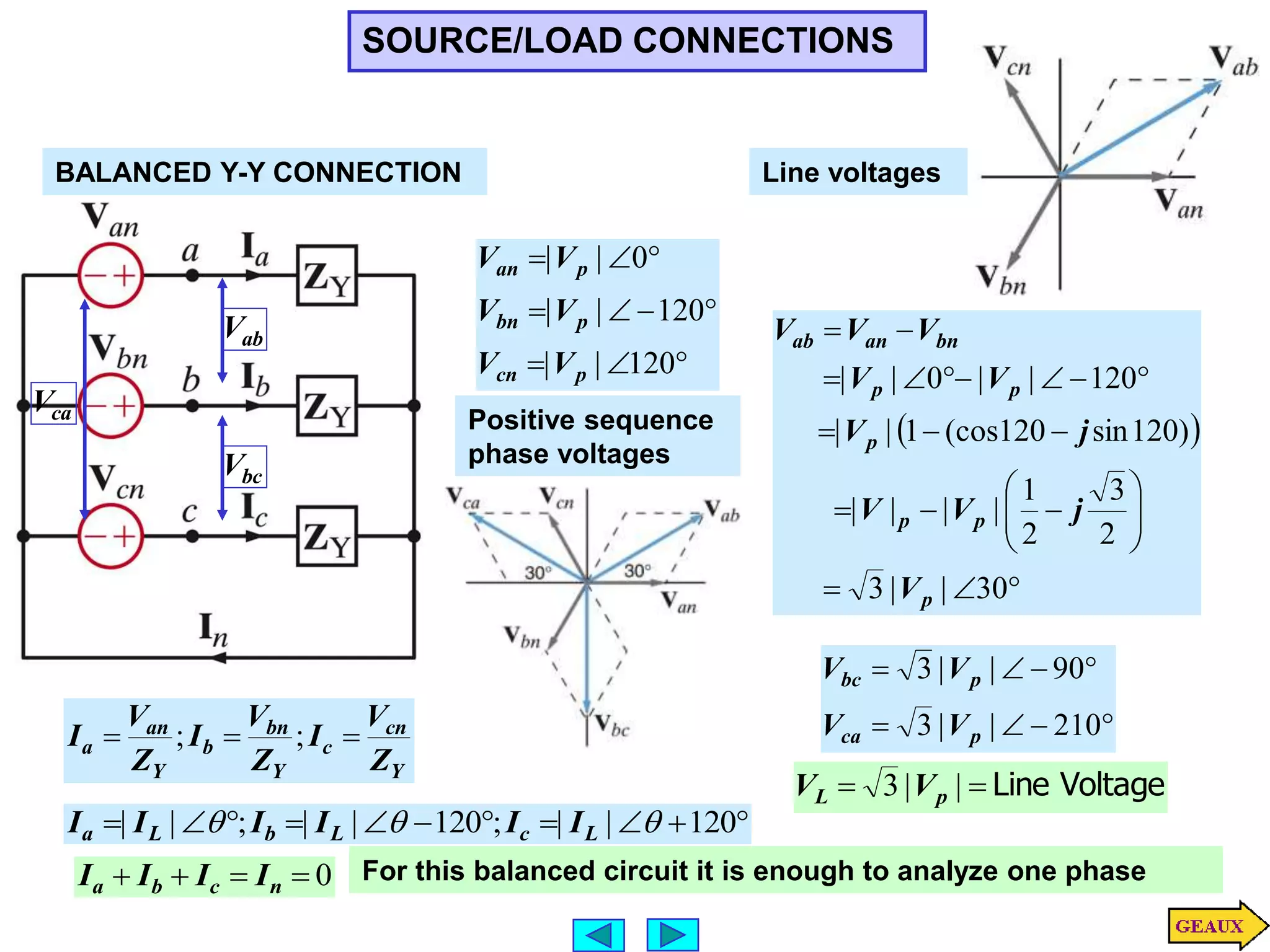
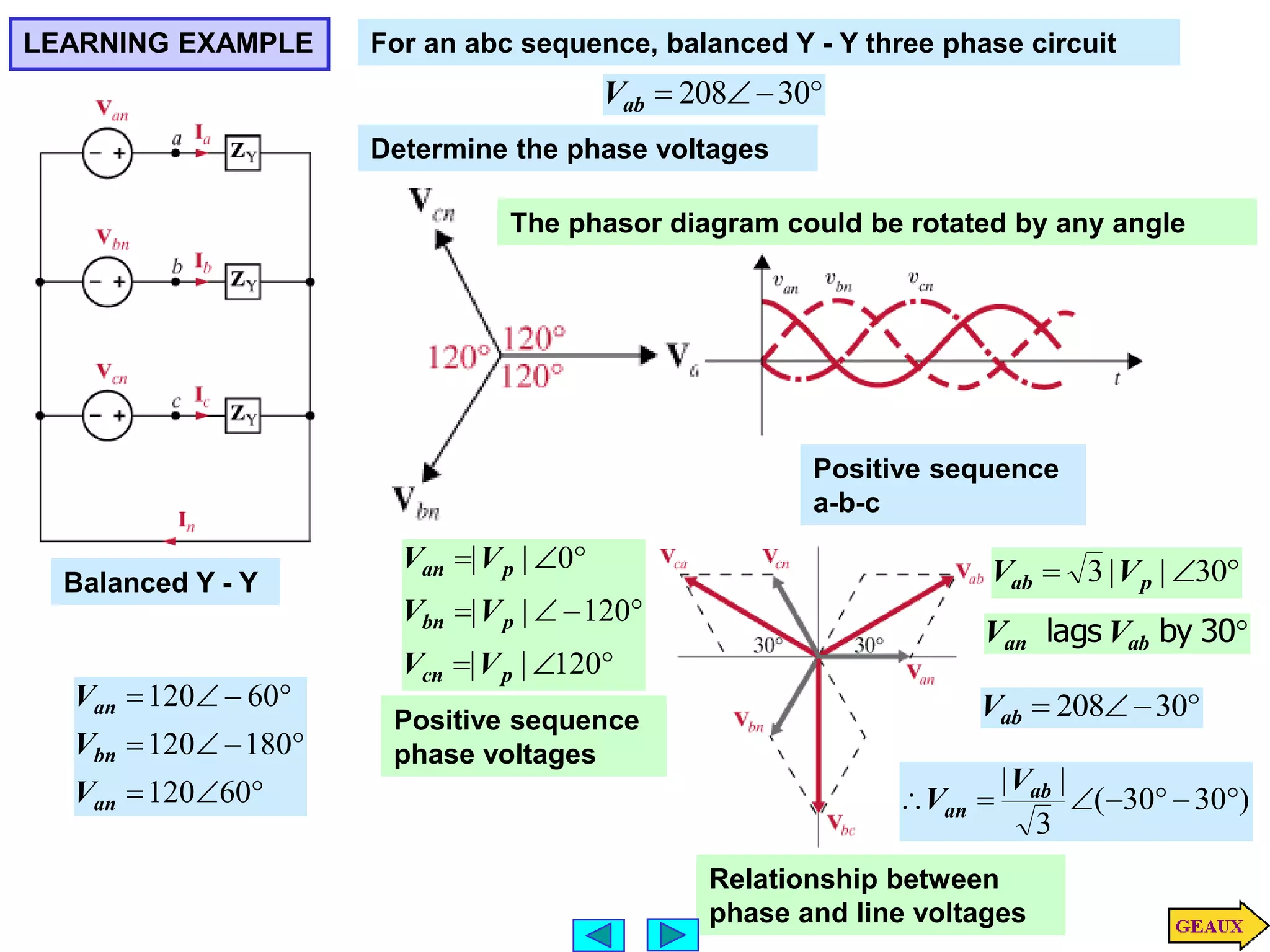
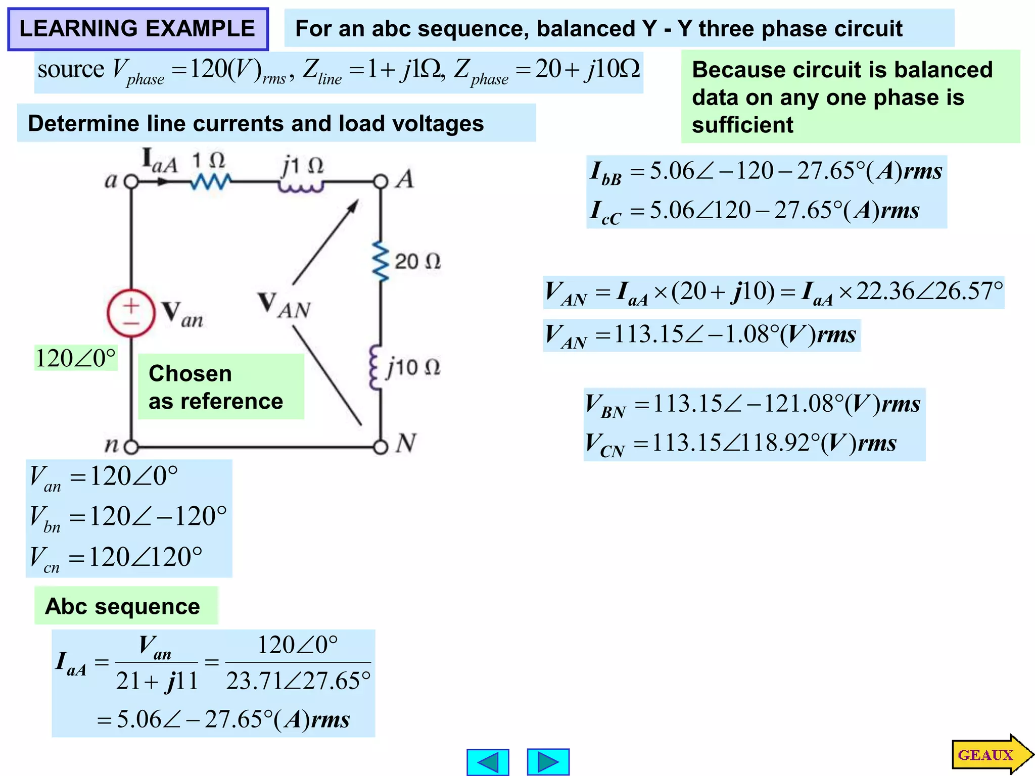
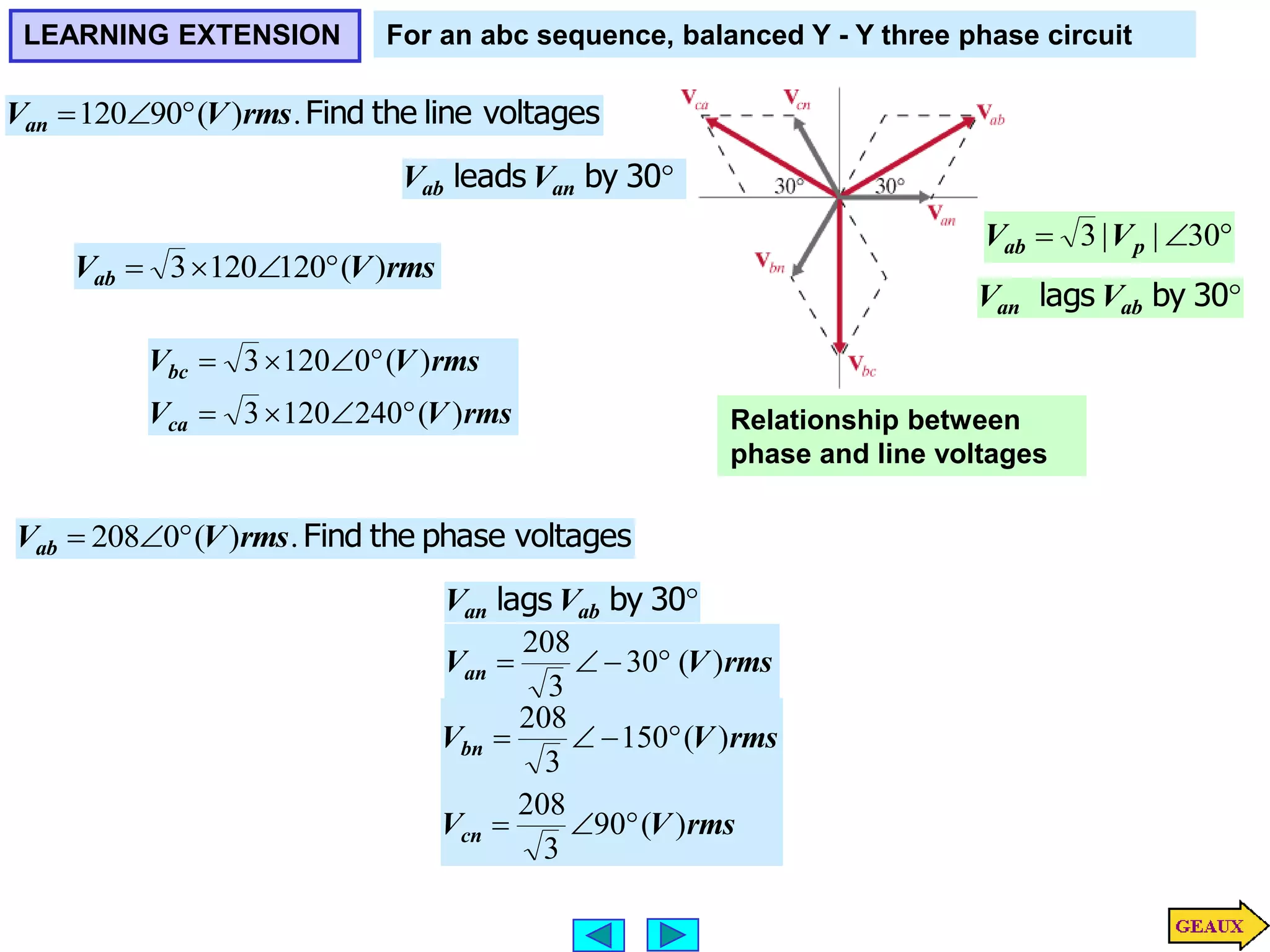
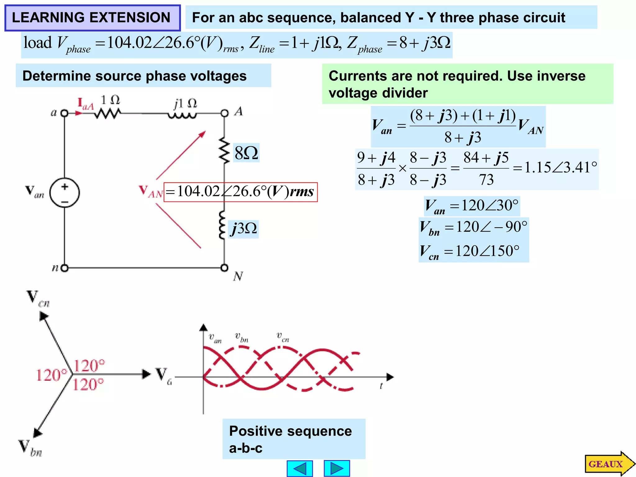
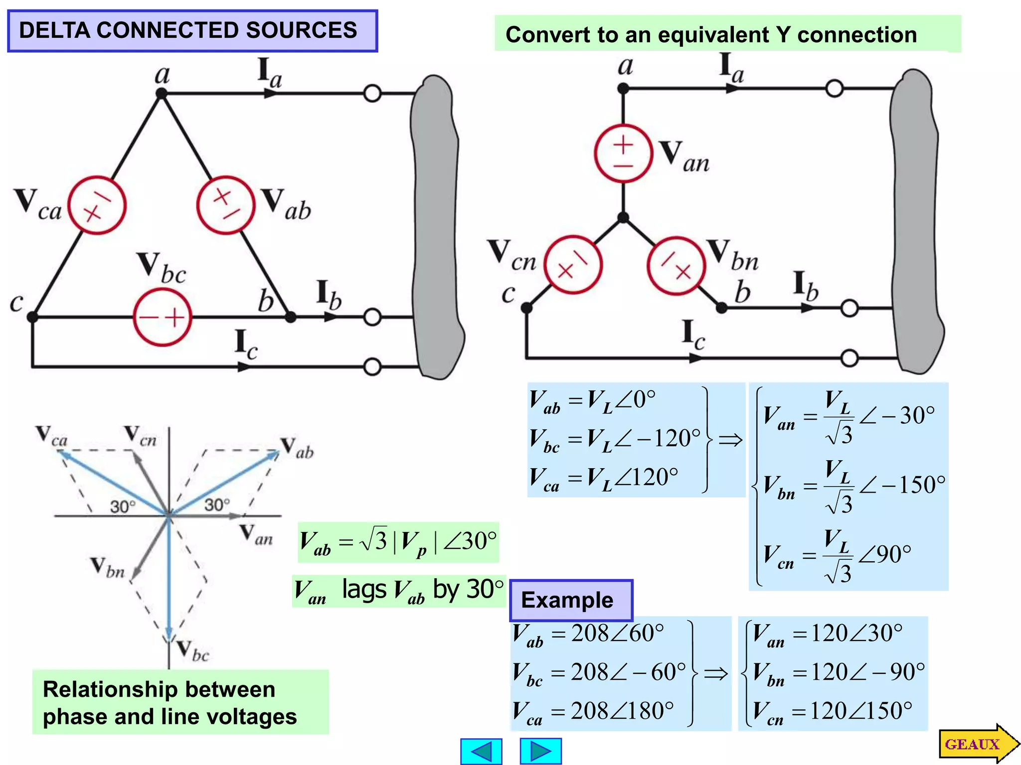
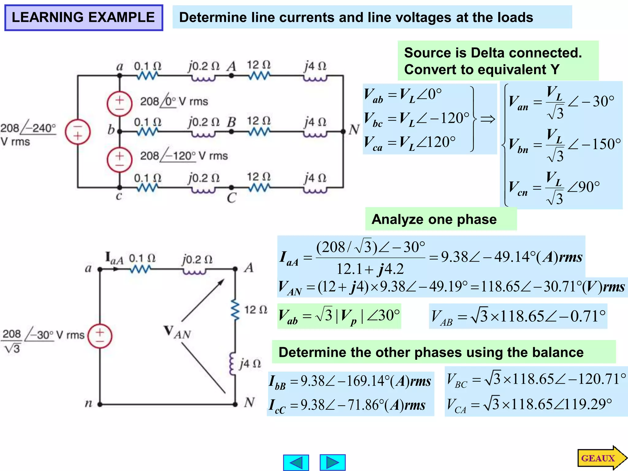
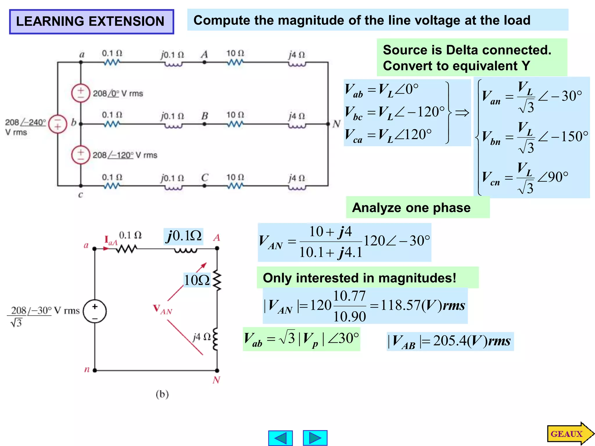
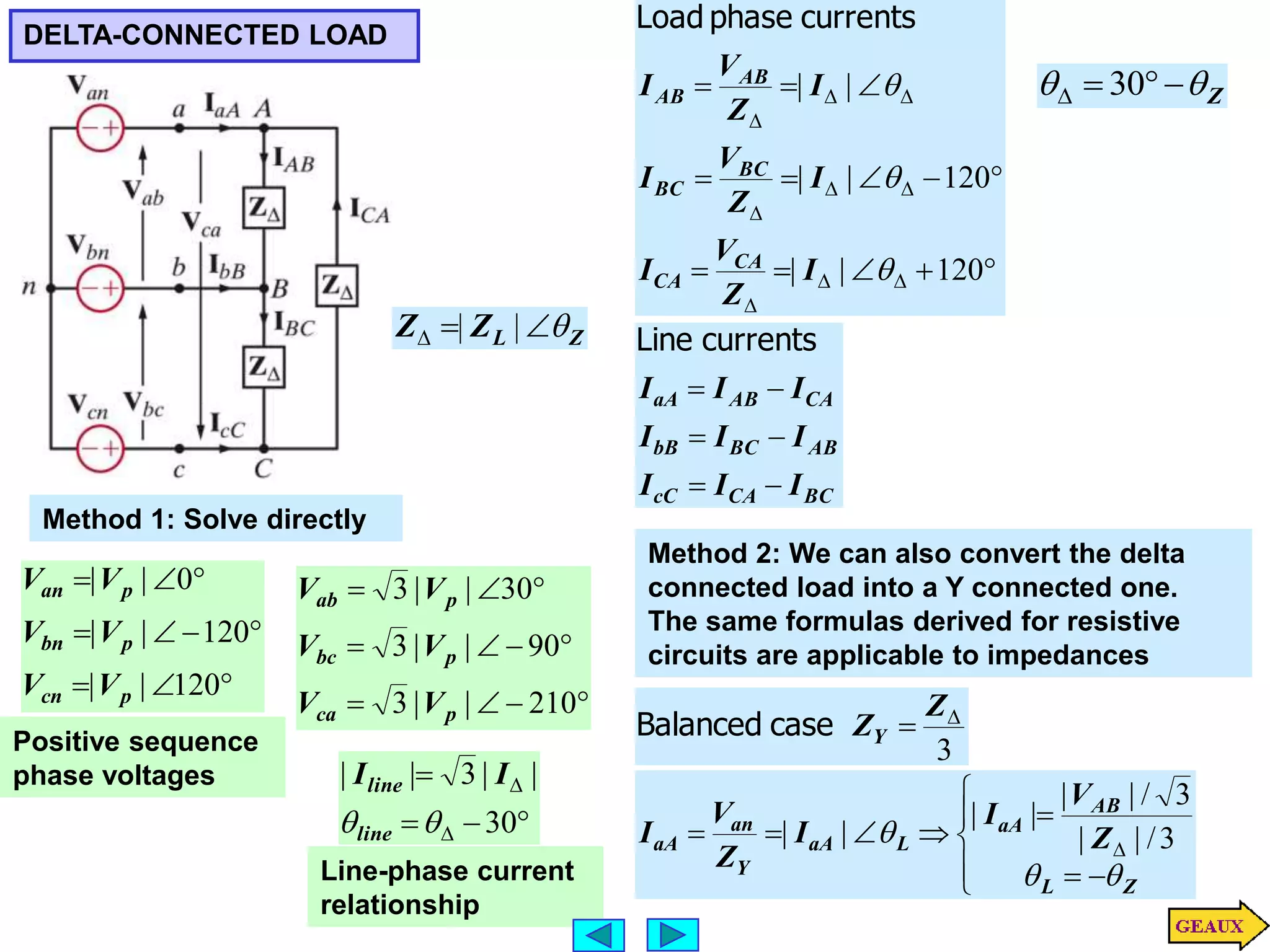
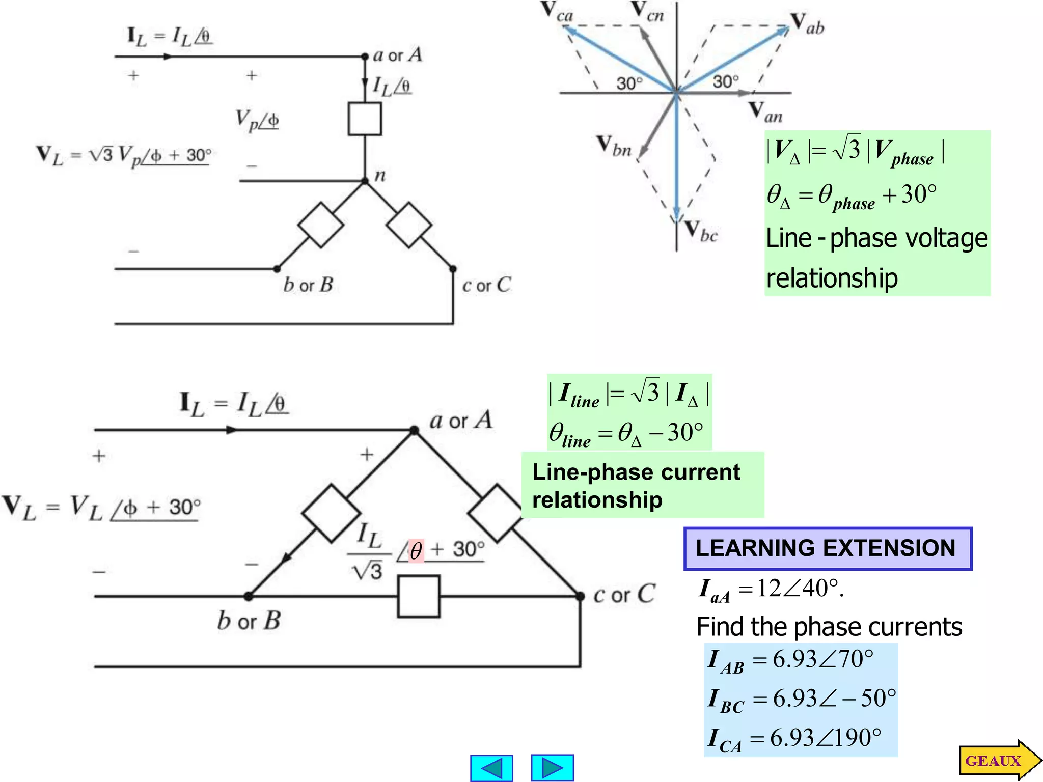
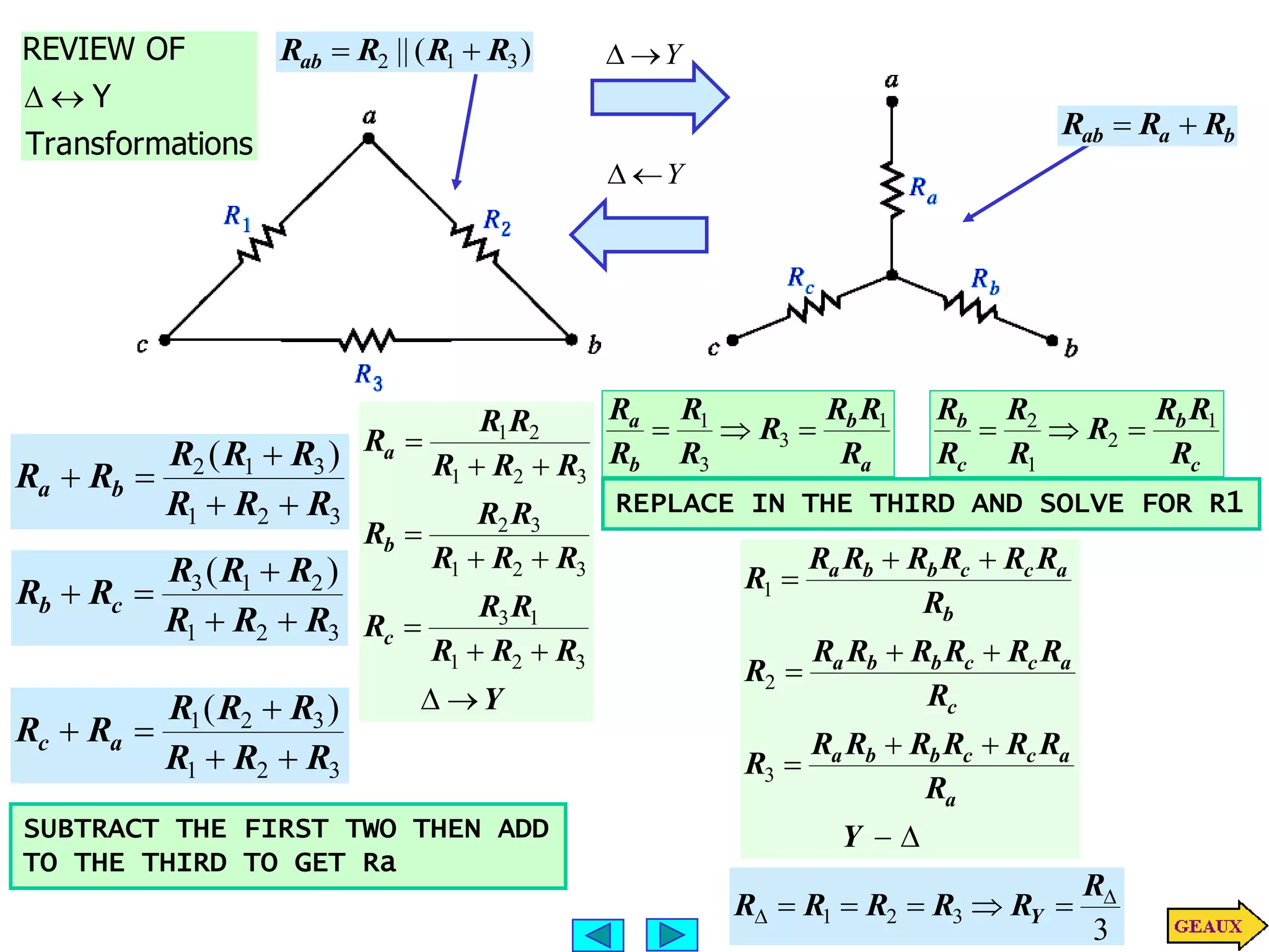
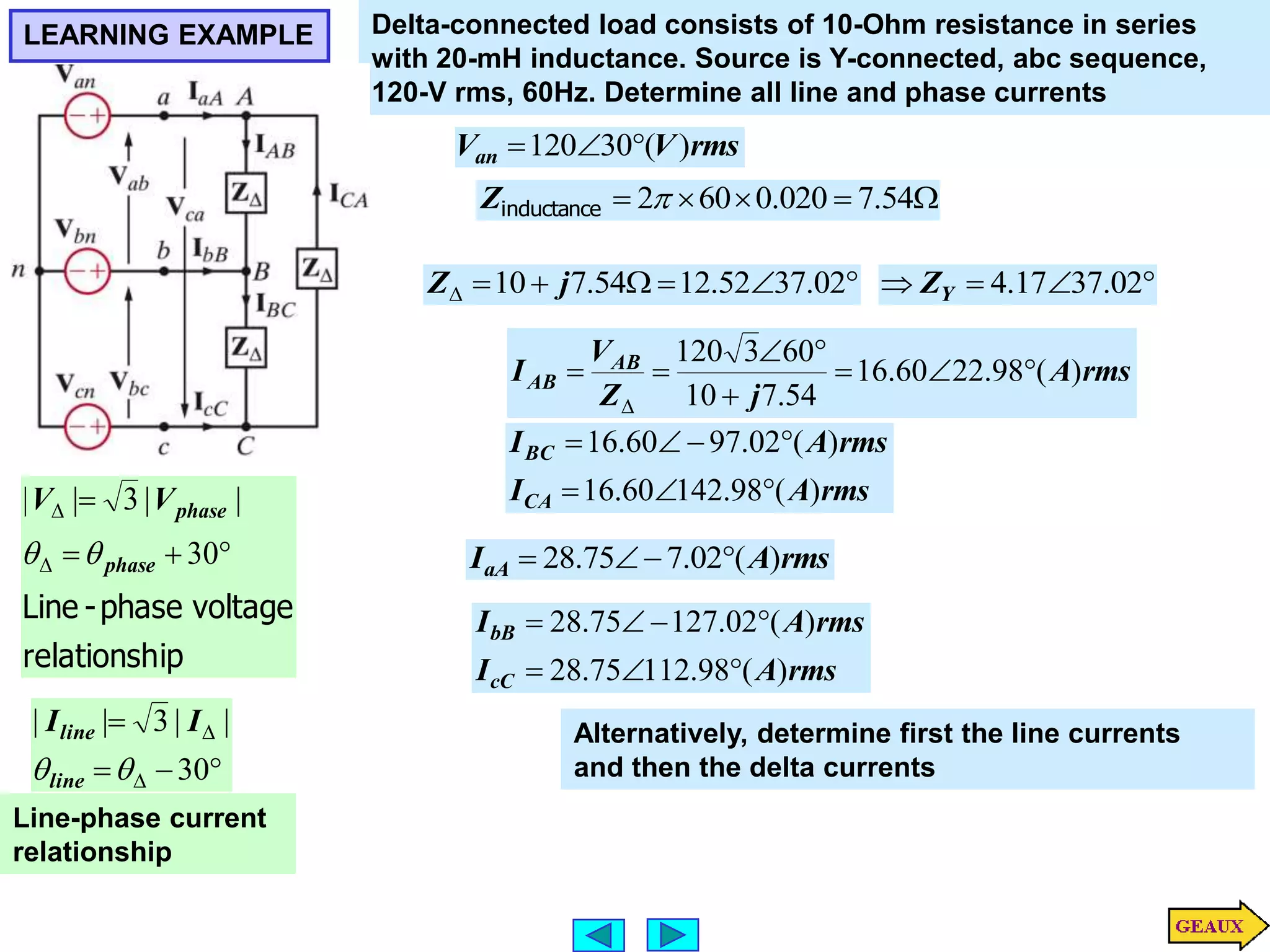
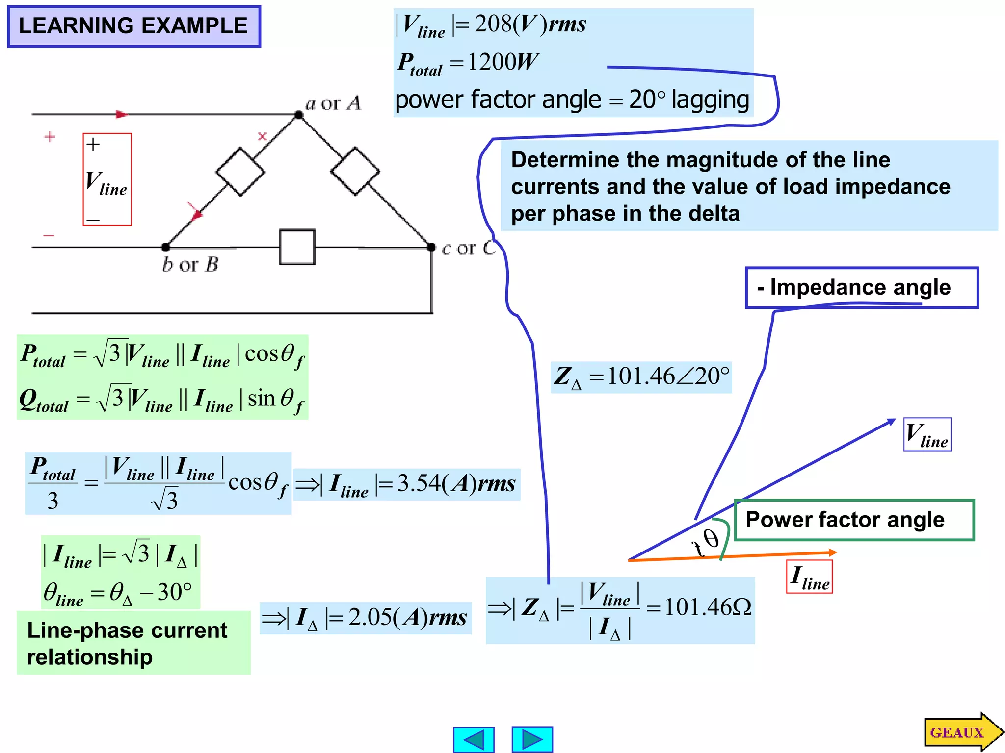
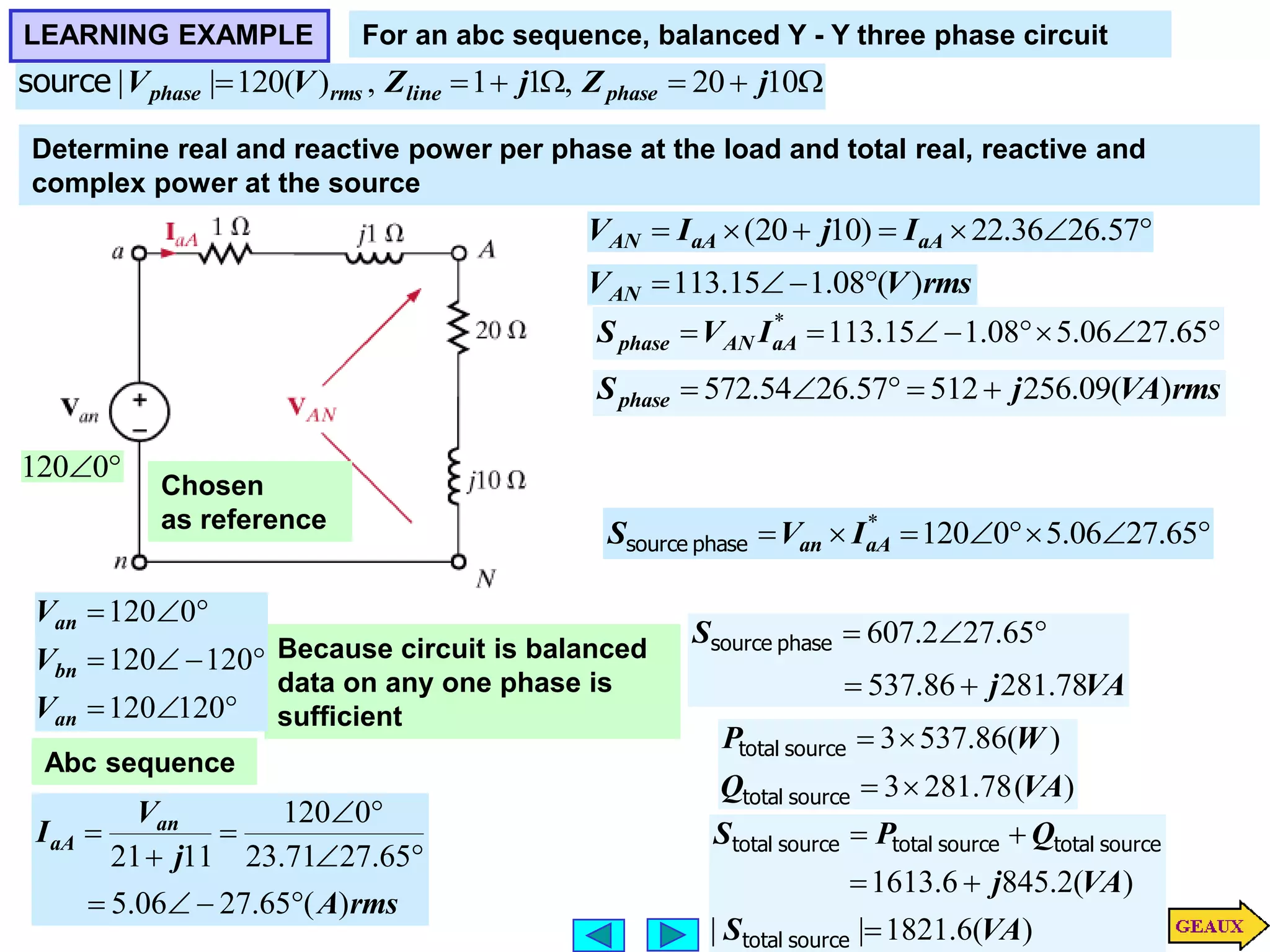
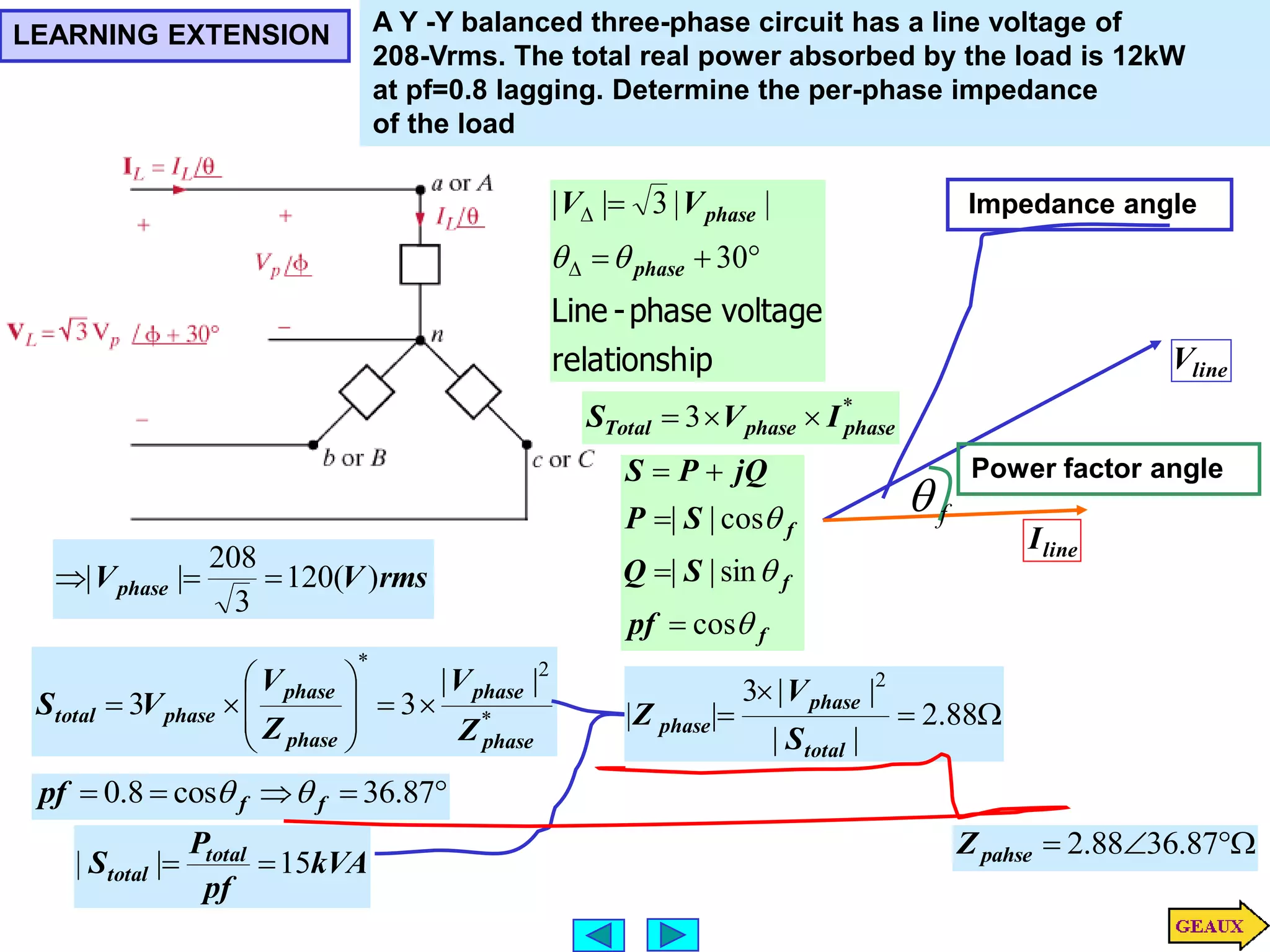
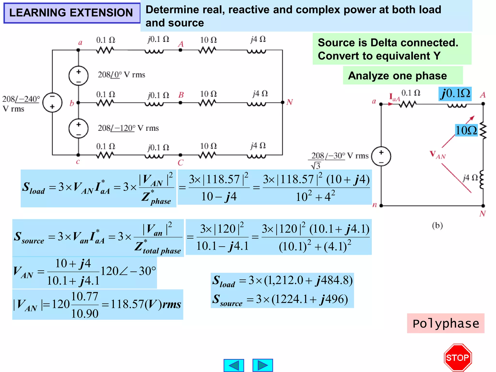
SlideShare a Scribd company logo
1 of 21
POLYPHASE CIRCUITS
LEARNING GOALS
Three Phase Circuits
Advantages of polyphase circuits
Three Phase Connections
Basic configurations for three phase circuits
Source/Load Connections
Delta-Wye connections
Power Relationships
Study power delivered by three phase circuits
THREE PHASE CIRCUITS
)
)(
240
cos(
)
(
)
)(
120
cos(
)
(
)
)(
cos(
)
(
V
t
V
t
v
V
t
V
t
v
V
t
V
t
v
m
c
m
bn
m
an










Voltages
Phase
ous
Instantane
a
i
b
i
c
i
)
240
cos(
)
(
)
120
cos(
)
(
)
cos(
)
(
















t
I
t
i
t
I
t
i
t
I
t
i
m
c
m
b
m
a
Currents
Phase
Balanced
2
120

m
V
)
(
)
(
)
(
)
(
)
(
)
(
)
( t
i
t
v
t
i
t
v
t
i
t
v
t
p c
cn
b
bn
a
an 


power
ous
Instantane
Theorem
For a balanced three phase circuit the instantaneous power is constant
)
(
cos
2
3
)
( W
I
V
t
p m
m


Proof of Theorem
For a balanced three phase circuit the instantaneous power is constant
)
(
cos
2
3
)
( W
I
V
t
p m
m

























)
240
cos(
)
240
cos(
)
120
cos(
)
120
cos(
)
cos(
cos
)
(
)
(
)
(
)
(
)
(
)
(
)
(
)
(









t
t
t
t
t
t
I
V
t
p
t
i
t
v
t
i
t
v
t
i
t
v
t
p
m
m
c
cn
b
bn
a
an
power
ous
Instantane
 
)
cos(
)
cos(
2
1
cos
cos 




 



3cos cos(2 )
( ) cos(2 240 )
2
cos(2 480 )
m m
t
V I
p t t
t
  
 
 
 
 
 
 
 
 
   
  
)
120
sin(
sin
)
120
cos(
cos
)
120
cos(
)
120
sin(
sin
)
120
cos(
cos
)
120
cos(
cos
cos
0
)
120
cos(
)
120
cos(
cos























Proof
Lemma
5
.
0
)
120
cos( 

0
)
120
cos(
)
120
cos(
cos 



 


)
120
cos(
)
480
cos(
)
120
cos(
)
240
cos(














 t
THREE-PHASE CONNECTIONS
Positive sequence
a-b-c
Y-connected
loads Delta connected loads
SOURCE/LOAD CONNECTIONS
BALANCED Y-Y CONNECTION










120
|
|
120
|
|
0
|
|
p
cn
p
bn
p
an
V
V
V
V
V
V
Positive sequence
phase voltages
ab
V
bc
V
ca
V
Line voltages
 

























30
|
|
3
2
3
2
1
|
|
|
|
)
120
sin
120
(cos
1
|
|
120
|
|
0
|
|
p
p
p
p
p
p
bn
an
ab
V
j
V
V
j
V
V
V
V
V
V








210
|
|
3
90
|
|
3
p
ca
p
bc
V
V
V
V
Voltage
Line

 |
|
3 p
L V
V
Y
cn
c
Y
bn
b
Y
an
a
Z
V
I
Z
V
I
Z
V
I 

 ;
;










 120
|
|
;
120
|
|
;
|
| 

 L
c
L
b
L
a I
I
I
I
I
I
0



 n
c
b
a I
I
I
I For this balanced circuit it is enough to analyze one phase
Relationship between
phase and line voltages
LEARNING EXAMPLE For an abc sequence, balanced Y - Y three phase circuit



 30
208
ab
V
Determine the phase voltages
Balanced Y - Y
Positive sequence
a-b-c


 30
|
|
3 p
ab V
V










120
|
|
120
|
|
0
|
|
p
cn
p
bn
p
an
V
V
V
V
V
V
Positive sequence
phase voltages
)
30
30
(
3
|
|






 ab
an
V
V

30
by
lags ab
an V
V



 30
208
ab
V











60
120
180
120
60
120
an
bn
an
V
V
V
The phasor diagram could be rotated by any angle
LEARNING EXAMPLE For an abc sequence, balanced Y - Y three phase circuit
source 120( ) , 1 1 , 20 10
rms
phase line phase
V V Z j Z j
      
Determine line currents and load voltages
Because circuit is balanced
data on any one phase is
sufficient

0
120
Chosen
as reference
120 0
120 120
120 120
an
bn
cn
V
V
V
  
  
  
Abc sequence
rms
A
j
V
I an
aA
)
(
65
.
27
06
.
5
65
.
27
71
.
23
0
120
11
21











rms
A
I
rms
A
I
cC
bB
)
(
65
.
27
120
06
.
5
)
(
65
.
27
120
06
.
5















 57
.
26
36
.
22
)
10
20
( aA
aA
AN I
j
I
V
rms
V
VAN )
(
08
.
1
15
.
113 



rms
V
V
rms
V
V
CN
BN
)
(
92
.
118
15
.
113
)
(
08
.
121
15
.
113







LEARNING EXTENSION For an abc sequence, balanced Y - Y three phase circuit
voltages
line
the
Find
.
)
(
90
120 rms
V
Van 


Relationship between
phase and line voltages


 30
|
|
3 p
ab V
V

30
by
lags ab
an V
V
30
by
leads 
an
ab V
V
rms
V
Vab )
(
120
120
3 



rms
V
V
rms
V
V
ca
bc
)
(
240
120
3
)
(
0
120
3








voltages
phase
the
Find
.
)
(
0
208 rms
V
Vab 



30
by
lags ab
an V
V
rms
V
Van )
(
30
3
208




rms
V
V
rms
V
V
cn
bn
)
(
90
3
208
)
(
150
3
208







LEARNING EXTENSION For an abc sequence, balanced Y - Y three phase circuit
load 104.02 26.6 ( ) , 1 1 , 8 3
rms
phase line phase
V V Z j Z j
        
Determine source phase voltages
rms
V)
(
6
.
26
02
.
104 



8

3
j
Currents are not required. Use inverse
voltage divider
AN
an V
j
j
j
V
3
8
)
1
1
(
)
3
8
(















41
.
3
15
.
1
73
5
84
3
8
3
8
3
8
4
9 j
j
j
j
j


 30
120
an
V
Positive sequence
a-b-c







150
120
90
120
cn
bn
V
V
DELTA CONNECTED SOURCES
Relationship between
phase and line voltages


 30
|
|
3 p
ab V
V

30
by
lags ab
an V
V
















120
120
0
L
ca
L
bc
L
ab
V
V
V
V
V
V




















90
3
150
3
30
3
L
cn
L
bn
L
an
V
V
V
V
V
V















150
120
90
120
30
120
cn
bn
an
V
V
V
















180
208
60
208
60
208
ca
bc
ab
V
V
V
Example
Convert to an equivalent Y connection
LEARNING EXAMPLE Determine line currents and line voltages at the loads
Source is Delta connected.
Convert to equivalent Y
















120
120
0
L
ca
L
bc
L
ab
V
V
V
V
V
V




















90
3
150
3
30
3
L
cn
L
bn
L
an
V
V
V
V
V
V
Analyze one phase
rms
A
j
IaA )
(
14
.
49
38
.
9
2
.
4
1
.
12
30
)
3
/
208
(









rms
V
j
VAN )
(
71
.
30
65
.
118
19
.
49
38
.
9
)
4
12
( 









Determine the other phases using the balance
rms
A
I
rms
A
I
cC
bB
)
(
86
.
71
38
.
9
)
(
14
.
169
38
.
9










 30
|
|
3 p
ab V
V 3 118.65 0.71
AB
V    
3 118.65 120.71
3 118.65 119.29
BC
CA
V
V
   
   
LEARNING EXTENSION Compute the magnitude of the line voltage at the load
Source is Delta connected.
Convert to equivalent Y
















120
120
0
L
ca
L
bc
L
ab
V
V
V
V
V
V




















90
3
150
3
30
3
L
cn
L
bn
L
an
V
V
V
V
V
V
Analyze one phase





 30
120
1
.
4
1
.
10
4
10
j
j
VAN

10

1
.
0
j
Only interested in magnitudes!
rms
V
VAN )
(
57
.
118
90
.
10
77
.
10
120
|
| 



 30
|
|
3 p
ab V
V rms
V
VAB )
(
4
.
205
|
| 
DELTA-CONNECTED LOAD
Method 1: Solve directly










120
|
|
120
|
|
0
|
|
p
cn
p
bn
p
an
V
V
V
V
V
V
Positive sequence
phase voltages











210
|
|
3
90
|
|
3
30
|
|
3
p
ca
p
bc
p
ab
V
V
V
V
V
V






















120
|
|
120
|
|
|
|



I
Z
V
I
I
Z
V
I
I
Z
V
I
CA
CA
BC
BC
AB
AB
currents
phase
Load
BC
CA
cC
AB
BC
bB
CA
AB
aA
I
I
I
I
I
I
I
I
I






currents
Line
Method 2: We can also convert the delta
connected load into a Y connected one.
The same formulas derived for resistive
circuits are applicable to impedances
3


Z
ZY
case
Balanced











 
Z
L
AB
aA
L
aA
Y
an
aA Z
V
I
I
Z
V
I


 3
/
|
|
3
/
|
|
|
|
|
|
Z
L
Z
Z 


 |
|
Z

 


 30






30
|
|
3
|
|

line
line I
I
Line-phase current
relationship







30
|
|
3
|
|

line
line I
I
Line-phase current
relationship
ip
relationsh
voltage
phase
-
Line






30
|
|
3
|
|
phase
phase
V
V


LEARNING EXTENSION
currents
phase
the
Find
.
40
12 


aA
I










190
93
.
6
50
93
.
6
70
93
.
6
CA
BC
AB
I
I
I
Y


b
a
ab R
R
R 

)
(
|| 3
1
2 R
R
R
Rab 

3
2
1
3
1
2 )
(
R
R
R
R
R
R
R
R b
a





3
2
1
2
1
3 )
(
R
R
R
R
R
R
R
R c
b





3
2
1
3
2
1 )
(
R
R
R
R
R
R
R
R a
c





SUBTRACT THE FIRST TWO THEN ADD
TO THE THIRD TO GET Ra
a
b
b
a
R
R
R
R
R
R
R
R 1
3
3
1



c
b
c
b
R
R
R
R
R
R
R
R 1
2
1
2



REPLACE IN THE THIRD AND SOLVE FOR R1
Y
R
R
R
R
R
R
R
R
R
R
R
R
R
R
R
R
R
R
c
b
a











3
2
1
1
3
3
2
1
3
2
3
2
1
2
1











Y
R
R
R
R
R
R
R
R
R
R
R
R
R
R
R
R
R
R
R
R
R
R
R
R
a
a
c
c
b
b
a
c
a
c
c
b
b
a
b
a
c
c
b
b
a
3
2
1
tions
Transforma
Y
OF
REVIEW


3
3
2
1

 




R
R
R
R
R
R Y
Y


LEARNING EXAMPLE






 02
.
37
52
.
12
54
.
7
10 j
Z
Delta-connected load consists of 10-Ohm resistance in series
with 20-mH inductance. Source is Y-connected, abc sequence,
120-V rms, 60Hz. Determine all line and phase currents
rms
V
Van )
(
30
120 






 54
.
7
020
.
0
60
2
inductance
Z
rms
A
j
Z
V
I AB
AB )
(
98
.
22
60
.
16
54
.
7
10
60
3
120















30
|
|
3
|
|

line
line I
I
Line-phase current
relationship
ip
relationsh
voltage
phase
-
Line






30
|
|
3
|
|
phase
phase
V
V

 rms
A
IaA )
(
02
.
7
75
.
28 



rms
A
I
rms
A
I
CA
BC
)
(
98
.
142
60
.
16
)
(
02
.
97
60
.
16







rms
A
I
rms
A
I
cC
bB
)
(
98
.
112
75
.
28
)
(
02
.
127
75
.
28










 02
.
37
17
.
4
Y
Z
Alternatively, determine first the line currents
and then the delta currents
POWER RELATIONSHIPS

ip
relationsh
voltage
phase
-
Line






30
|
|
3
|
|
phase
phase
V
V








30
|
|
3
|
|

line
line I
I
Line-phase current
relationship
*
3
Total phase line
S V I

*
3 line
line
Total I
V
S 
*
3 

 I
V
S line
total
*
3 line
line
Total I
V
S 
line
V
line
I
Power factor angle
f 
f
line
line
total
f
line
line
total
I
V
Q
I
V
P


sin
|
||
|
3
cos
|
||
|
3


- Impedance angle
LEARNING EXAMPLE
lagging
20
angle
factor
power 



W
P
rms
V
V
total
line
1200
)
(
208
|
|
Determine the magnitude of the line
currents and the value of load impedance
per phase in the delta
f
line
line
total
f
line
line
total
I
V
Q
I
V
P


sin
|
||
|
3
cos
|
||
|
3


f
line
line
total I
V
P

cos
3
|
||
|
3
 rms
A
Iline )
(
54
.
3
|
| 







30
|
|
3
|
|

line
line I
I
Line-phase current
relationship
rms
A
I )
(
05
.
2
|
| 
 





 46
.
101
|
|
|
|
|
|
I
V
Z line



 20
46
.
101
Z
line
V
line
I
Power factor angle
f 
- Impedance angle


line
V
LEARNING EXAMPLE For an abc sequence, balanced Y - Y three phase circuit






 10
20
,
1
1
,
)
(
120
|
| j
Z
j
Z
V
V phase
line
rms
phase
source
Because circuit is balanced
data on any one phase is
sufficient

0
120
Chosen
as reference










120
120
120
120
0
120
an
bn
an
V
V
V
Abc sequence
rms
A
j
V
I an
aA
)
(
65
.
27
06
.
5
65
.
27
71
.
23
0
120
11
21











Determine real and reactive power per phase at the load and total real, reactive and
complex power at the source






 57
.
26
36
.
22
)
10
20
( aA
aA
AN I
j
I
V
rms
V
VAN )
(
08
.
1
15
.
113 










 65
.
27
06
.
5
08
.
1
15
.
113
*
aA
AN
phase I
V
S
rms
VA
j
Sphase )
(
09
.
256
512
57
.
26
54
.
572 











 65
.
27
06
.
5
0
120
*
aA
an I
V
S phase
source
VA
j
S
78
.
281
86
.
537
65
.
27
2
.
607





phase
source
)
(
78
.
281
3
)
(
86
.
537
3
VA
Q
W
P




source
total
source
total
)
(
6
.
1821
|
|
)
(
2
.
845
6
.
1613
VA
S
VA
j
Q
P
S





source
total
source
total
source
total
source
total
LEARNING EXTENSION A Y -Y balanced three-phase circuit has a line voltage of
208-Vrms. The total real power absorbed by the load is 12kW
at pf=0.8 lagging. Determine the per-phase impedance
of the load
ip
relationsh
voltage
phase
-
Line






30
|
|
3
|
|
phase
phase
V
V


*
3 phase
phase
Total I
V
S 


rms
V
Vphase )
(
120
3
208
|
| 


*
2
*
|
|
3
3
phase
phase
phase
phase
phase
total
Z
V
Z
V
V
S 











line
V
line
I
Power factor angle
Impedance angle




 87
.
36
cos
8
.
0 f
f
pf 

f
f
f
pf
S
Q
S
P
jQ
P
S



cos
sin
|
|
cos
|
|





kVA
pf
P
S total
total 15
|
| 




 88
.
2
|
|
|
|
3
|
|
2
total
phase
phase
S
V
Z



 87
.
36
88
.
2
pahse
Z
f






 30
120
1
.
4
1
.
10
4
10
j
j
VAN
Source is Delta connected.
Convert to equivalent Y
Analyze one phase

10

1
.
0
j
rms
V
VAN )
(
57
.
118
90
.
10
77
.
10
120
|
| 

LEARNING EXTENSION Determine real, reactive and complex power at both load
and source
*
2
* |
|
3
3
phase
AN
aA
AN
load
Z
V
I
V
S 



*
2
* |
|
3
3
phase
total
an
aA
an
source
Z
V
I
V
S 



2
2
2
2
4
10
)
4
10
(
|
57
.
118
|
3
4
10
|
57
.
118
|
3







j
j
2
2
2
2
)
1
.
4
(
)
1
.
10
(
)
1
.
4
1
.
10
(
|
120
|
3
1
.
4
1
.
10
|
120
|
3







j
j
)
496
1
.
1224
(
3
)
8
.
484
0
.
212
,
1
(
3
j
S
j
S
source
load






Polyphase

More Related Content

What's hot

Ee1 chapter12 phasor_diagram
Ee1 chapter12 phasor_diagramEe1 chapter12 phasor_diagram
Ee1 chapter12 phasor_diagram
CK Yang
 
Network theorems for electrical engineering
Network theorems for electrical engineeringNetwork theorems for electrical engineering
Network theorems for electrical engineering
Kamil Hussain
 

What's hot (20)

Short Circuit Calculation Symmetrical & Asymmetrical Fault Currents ?
Short Circuit Calculation Symmetrical & Asymmetrical Fault Currents ?Short Circuit Calculation Symmetrical & Asymmetrical Fault Currents ?
Short Circuit Calculation Symmetrical & Asymmetrical Fault Currents ?
 
PERFORMANCE OF TRANSMISSION LINES:
PERFORMANCE OF TRANSMISSION LINES:PERFORMANCE OF TRANSMISSION LINES:
PERFORMANCE OF TRANSMISSION LINES:
 
Capitulo 5, 7ma edición
Capitulo 5, 7ma ediciónCapitulo 5, 7ma edición
Capitulo 5, 7ma edición
 
Chapter 4 frequency modulation
Chapter 4 frequency modulationChapter 4 frequency modulation
Chapter 4 frequency modulation
 
基本電學Ii(劉版)自我評量
基本電學Ii(劉版)自我評量基本電學Ii(劉版)自我評量
基本電學Ii(劉版)自我評量
 
Dinamica ejercicios
Dinamica ejerciciosDinamica ejercicios
Dinamica ejercicios
 
Superposition theorem
Superposition theoremSuperposition theorem
Superposition theorem
 
Biquad Filter
Biquad FilterBiquad Filter
Biquad Filter
 
Transmission lines
Transmission linesTransmission lines
Transmission lines
 
Lecture 4
Lecture 4Lecture 4
Lecture 4
 
Oscillator
OscillatorOscillator
Oscillator
 
Amplitude Modulation using Multipliers and Envelope Detector
Amplitude Modulation using Multipliers and Envelope DetectorAmplitude Modulation using Multipliers and Envelope Detector
Amplitude Modulation using Multipliers and Envelope Detector
 
Ee1 chapter12 phasor_diagram
Ee1 chapter12 phasor_diagramEe1 chapter12 phasor_diagram
Ee1 chapter12 phasor_diagram
 
Network theorems for electrical engineering
Network theorems for electrical engineeringNetwork theorems for electrical engineering
Network theorems for electrical engineering
 
Electrical Circuit.pdf
Electrical Circuit.pdfElectrical Circuit.pdf
Electrical Circuit.pdf
 
3 phase ac
3 phase ac3 phase ac
3 phase ac
 
2.RedesYCircuitos.pptx
2.RedesYCircuitos.pptx2.RedesYCircuitos.pptx
2.RedesYCircuitos.pptx
 
AC-Alternative Current & Circuit Analysis ( Full of Information )
AC-Alternative Current & Circuit Analysis ( Full of Information )AC-Alternative Current & Circuit Analysis ( Full of Information )
AC-Alternative Current & Circuit Analysis ( Full of Information )
 
Ece 126
Ece 126Ece 126
Ece 126
 
Content beyond syllabus
Content beyond syllabusContent beyond syllabus
Content beyond syllabus
 

Similar to Chapter 2 ( A) - Polyphase Circuits .ppt

Space vector pwm_inverter
Space vector pwm_inverterSpace vector pwm_inverter
Space vector pwm_inverter
ZunAib Ali
 

Similar to Chapter 2 ( A) - Polyphase Circuits .ppt (20)

BEF 23803 - Lesson 3 - Balanced Delta Load Thre-Phase Systems.ppt
BEF 23803 - Lesson 3 - Balanced Delta Load Thre-Phase Systems.pptBEF 23803 - Lesson 3 - Balanced Delta Load Thre-Phase Systems.ppt
BEF 23803 - Lesson 3 - Balanced Delta Load Thre-Phase Systems.ppt
 
Basic 3 Phase (1).ppt
Basic 3 Phase (1).pptBasic 3 Phase (1).ppt
Basic 3 Phase (1).ppt
 
Three Phases Circuit.pdf
Three Phases Circuit.pdfThree Phases Circuit.pdf
Three Phases Circuit.pdf
 
Three Phase Theory
Three Phase TheoryThree Phase Theory
Three Phase Theory
 
AC CIRCUIT
AC CIRCUITAC CIRCUIT
AC CIRCUIT
 
Three phase-circuits
Three phase-circuitsThree phase-circuits
Three phase-circuits
 
Lec 1.ppt
Lec 1.pptLec 1.ppt
Lec 1.ppt
 
3phase unit 2.ppt
3phase unit 2.ppt3phase unit 2.ppt
3phase unit 2.ppt
 
Lecture Notes ELE A6.pdf
Lecture Notes ELE A6.pdfLecture Notes ELE A6.pdf
Lecture Notes ELE A6.pdf
 
Lecture Notes ELE A6.pdf
Lecture Notes ELE A6.pdfLecture Notes ELE A6.pdf
Lecture Notes ELE A6.pdf
 
UNIT-III complex reactive three phase.ppt
UNIT-III complex reactive three phase.pptUNIT-III complex reactive three phase.ppt
UNIT-III complex reactive three phase.ppt
 
power system analysis lecture 1
power system analysis lecture 1power system analysis lecture 1
power system analysis lecture 1
 
BEF 23803 - Polyphase Circuit Analysis - Lecture 2.pptx
BEF 23803 - Polyphase Circuit Analysis - Lecture 2.pptxBEF 23803 - Polyphase Circuit Analysis - Lecture 2.pptx
BEF 23803 - Polyphase Circuit Analysis - Lecture 2.pptx
 
Advanced Polyphase Metering
Advanced Polyphase MeteringAdvanced Polyphase Metering
Advanced Polyphase Metering
 
Three Phase Circuit_2 (1).ppt
Three Phase Circuit_2 (1).pptThree Phase Circuit_2 (1).ppt
Three Phase Circuit_2 (1).ppt
 
Three phase System
Three phase SystemThree phase System
Three phase System
 
Term question eee 305
Term question eee 305Term question eee 305
Term question eee 305
 
BEE PPT 362.pptx
BEE PPT 362.pptxBEE PPT 362.pptx
BEE PPT 362.pptx
 
AC Generator.ppt
AC Generator.pptAC Generator.ppt
AC Generator.ppt
 
Space vector pwm_inverter
Space vector pwm_inverterSpace vector pwm_inverter
Space vector pwm_inverter
 

More from LiewChiaPing

More from LiewChiaPing (20)

chapter4 DC to AC Converter.ppt
chapter4 DC to AC Converter.pptchapter4 DC to AC Converter.ppt
chapter4 DC to AC Converter.ppt
 
chapter_2 AC to DC Converter.pptx
chapter_2 AC to DC Converter.pptxchapter_2 AC to DC Converter.pptx
chapter_2 AC to DC Converter.pptx
 
chapter_1 Intro. to electonic Devices.ppt
chapter_1 Intro. to electonic Devices.pptchapter_1 Intro. to electonic Devices.ppt
chapter_1 Intro. to electonic Devices.ppt
 
Chapter 7 Application of Electronic Converters.pdf
Chapter 7 Application of Electronic Converters.pdfChapter 7 Application of Electronic Converters.pdf
Chapter 7 Application of Electronic Converters.pdf
 
Chapter 6 AC-AC Converters.pdf
Chapter 6 AC-AC Converters.pdfChapter 6 AC-AC Converters.pdf
Chapter 6 AC-AC Converters.pdf
 
Chapter 5 DC-DC Converters.pdf
Chapter 5 DC-DC Converters.pdfChapter 5 DC-DC Converters.pdf
Chapter 5 DC-DC Converters.pdf
 
Chapter 4 Inverters.pdf
Chapter 4 Inverters.pdfChapter 4 Inverters.pdf
Chapter 4 Inverters.pdf
 
Chapter 3 Controlled Rectifier.pdf
Chapter 3 Controlled Rectifier.pdfChapter 3 Controlled Rectifier.pdf
Chapter 3 Controlled Rectifier.pdf
 
Chapter 2 Uncontrolled Rectifiers.pdf
Chapter 2 Uncontrolled Rectifiers.pdfChapter 2 Uncontrolled Rectifiers.pdf
Chapter 2 Uncontrolled Rectifiers.pdf
 
Chapter 1 Introduction to power Electronic Devices.pdf
Chapter 1 Introduction to power Electronic Devices.pdfChapter 1 Introduction to power Electronic Devices.pdf
Chapter 1 Introduction to power Electronic Devices.pdf
 
BEF43303_-_201620171_W13 Overcurrent Protection.pdf
BEF43303_-_201620171_W13 Overcurrent Protection.pdfBEF43303_-_201620171_W13 Overcurrent Protection.pdf
BEF43303_-_201620171_W13 Overcurrent Protection.pdf
 
BEF43303_-_201620171_W12 Overcurrent Protection.pdf
BEF43303_-_201620171_W12 Overcurrent Protection.pdfBEF43303_-_201620171_W12 Overcurrent Protection.pdf
BEF43303_-_201620171_W12 Overcurrent Protection.pdf
 
BEF43303_-_201620171_W11 Distance Protection.pdf
BEF43303_-_201620171_W11 Distance Protection.pdfBEF43303_-_201620171_W11 Distance Protection.pdf
BEF43303_-_201620171_W11 Distance Protection.pdf
 
BEF43303_-_201620171_W10.pdf
BEF43303_-_201620171_W10.pdfBEF43303_-_201620171_W10.pdf
BEF43303_-_201620171_W10.pdf
 
BEF43303_-_201620171_W8 Power System Stability.pdf
BEF43303_-_201620171_W8 Power System Stability.pdfBEF43303_-_201620171_W8 Power System Stability.pdf
BEF43303_-_201620171_W8 Power System Stability.pdf
 
BEF43303_-_201620171_W7 Power System Stability.pdf
BEF43303_-_201620171_W7 Power System Stability.pdfBEF43303_-_201620171_W7 Power System Stability.pdf
BEF43303_-_201620171_W7 Power System Stability.pdf
 
BEF43303_-_201620171_W6 Analysis of Fault.pdf
BEF43303_-_201620171_W6 Analysis of Fault.pdfBEF43303_-_201620171_W6 Analysis of Fault.pdf
BEF43303_-_201620171_W6 Analysis of Fault.pdf
 
BEF43303_-_201620171_W5 Analysis of fault.pdf
BEF43303_-_201620171_W5 Analysis of fault.pdfBEF43303_-_201620171_W5 Analysis of fault.pdf
BEF43303_-_201620171_W5 Analysis of fault.pdf
 
BEF43303_-_201620171_W4 Analysis of Balance and Unbalance Fault.pdf
BEF43303_-_201620171_W4 Analysis of Balance and Unbalance Fault.pdfBEF43303_-_201620171_W4 Analysis of Balance and Unbalance Fault.pdf
BEF43303_-_201620171_W4 Analysis of Balance and Unbalance Fault.pdf
 
BEF43303 - 201620171 W3 Power Flow Analysis.pdf
BEF43303 - 201620171 W3 Power Flow Analysis.pdfBEF43303 - 201620171 W3 Power Flow Analysis.pdf
BEF43303 - 201620171 W3 Power Flow Analysis.pdf
 

Recently uploaded

The basics of sentences session 3pptx.pptx
The basics of sentences session 3pptx.pptxThe basics of sentences session 3pptx.pptx
The basics of sentences session 3pptx.pptx
heathfieldcps1
 
Spellings Wk 4 and Wk 5 for Grade 4 at CAPS
Spellings Wk 4 and Wk 5 for Grade 4 at CAPSSpellings Wk 4 and Wk 5 for Grade 4 at CAPS
Spellings Wk 4 and Wk 5 for Grade 4 at CAPS
AnaAcapella
 

Recently uploaded (20)

OSCM Unit 2_Operations Processes & Systems
OSCM Unit 2_Operations Processes & SystemsOSCM Unit 2_Operations Processes & Systems
OSCM Unit 2_Operations Processes & Systems
 
NO1 Top Black Magic Specialist In Lahore Black magic In Pakistan Kala Ilam Ex...
NO1 Top Black Magic Specialist In Lahore Black magic In Pakistan Kala Ilam Ex...NO1 Top Black Magic Specialist In Lahore Black magic In Pakistan Kala Ilam Ex...
NO1 Top Black Magic Specialist In Lahore Black magic In Pakistan Kala Ilam Ex...
 
80 ĐỀ THI THỬ TUYỂN SINH TIẾNG ANH VÀO 10 SỞ GD – ĐT THÀNH PHỐ HỒ CHÍ MINH NĂ...
80 ĐỀ THI THỬ TUYỂN SINH TIẾNG ANH VÀO 10 SỞ GD – ĐT THÀNH PHỐ HỒ CHÍ MINH NĂ...80 ĐỀ THI THỬ TUYỂN SINH TIẾNG ANH VÀO 10 SỞ GD – ĐT THÀNH PHỐ HỒ CHÍ MINH NĂ...
80 ĐỀ THI THỬ TUYỂN SINH TIẾNG ANH VÀO 10 SỞ GD – ĐT THÀNH PHỐ HỒ CHÍ MINH NĂ...
 
HMCS Vancouver Pre-Deployment Brief - May 2024 (Web Version).pptx
HMCS Vancouver Pre-Deployment Brief - May 2024 (Web Version).pptxHMCS Vancouver Pre-Deployment Brief - May 2024 (Web Version).pptx
HMCS Vancouver Pre-Deployment Brief - May 2024 (Web Version).pptx
 
HMCS Max Bernays Pre-Deployment Brief (May 2024).pptx
HMCS Max Bernays Pre-Deployment Brief (May 2024).pptxHMCS Max Bernays Pre-Deployment Brief (May 2024).pptx
HMCS Max Bernays Pre-Deployment Brief (May 2024).pptx
 
Tatlong Kwento ni Lola basyang-1.pdf arts
Tatlong Kwento ni Lola basyang-1.pdf artsTatlong Kwento ni Lola basyang-1.pdf arts
Tatlong Kwento ni Lola basyang-1.pdf arts
 
REMIFENTANIL: An Ultra short acting opioid.pptx
REMIFENTANIL: An Ultra short acting opioid.pptxREMIFENTANIL: An Ultra short acting opioid.pptx
REMIFENTANIL: An Ultra short acting opioid.pptx
 
Interdisciplinary_Insights_Data_Collection_Methods.pptx
Interdisciplinary_Insights_Data_Collection_Methods.pptxInterdisciplinary_Insights_Data_Collection_Methods.pptx
Interdisciplinary_Insights_Data_Collection_Methods.pptx
 
Introduction to TechSoup’s Digital Marketing Services and Use Cases
Introduction to TechSoup’s Digital Marketing  Services and Use CasesIntroduction to TechSoup’s Digital Marketing  Services and Use Cases
Introduction to TechSoup’s Digital Marketing Services and Use Cases
 
Details on CBSE Compartment Exam.pptx1111
Details on CBSE Compartment Exam.pptx1111Details on CBSE Compartment Exam.pptx1111
Details on CBSE Compartment Exam.pptx1111
 
COMMUNICATING NEGATIVE NEWS - APPROACHES .pptx
COMMUNICATING NEGATIVE NEWS - APPROACHES .pptxCOMMUNICATING NEGATIVE NEWS - APPROACHES .pptx
COMMUNICATING NEGATIVE NEWS - APPROACHES .pptx
 
Beyond_Borders_Understanding_Anime_and_Manga_Fandom_A_Comprehensive_Audience_...
Beyond_Borders_Understanding_Anime_and_Manga_Fandom_A_Comprehensive_Audience_...Beyond_Borders_Understanding_Anime_and_Manga_Fandom_A_Comprehensive_Audience_...
Beyond_Borders_Understanding_Anime_and_Manga_Fandom_A_Comprehensive_Audience_...
 
How to Add a Tool Tip to a Field in Odoo 17
How to Add a Tool Tip to a Field in Odoo 17How to Add a Tool Tip to a Field in Odoo 17
How to Add a Tool Tip to a Field in Odoo 17
 
Play hard learn harder: The Serious Business of Play
Play hard learn harder:  The Serious Business of PlayPlay hard learn harder:  The Serious Business of Play
Play hard learn harder: The Serious Business of Play
 
On_Translating_a_Tamil_Poem_by_A_K_Ramanujan.pptx
On_Translating_a_Tamil_Poem_by_A_K_Ramanujan.pptxOn_Translating_a_Tamil_Poem_by_A_K_Ramanujan.pptx
On_Translating_a_Tamil_Poem_by_A_K_Ramanujan.pptx
 
FICTIONAL SALESMAN/SALESMAN SNSW 2024.pdf
FICTIONAL SALESMAN/SALESMAN SNSW 2024.pdfFICTIONAL SALESMAN/SALESMAN SNSW 2024.pdf
FICTIONAL SALESMAN/SALESMAN SNSW 2024.pdf
 
What is 3 Way Matching Process in Odoo 17.pptx
What is 3 Way Matching Process in Odoo 17.pptxWhat is 3 Way Matching Process in Odoo 17.pptx
What is 3 Way Matching Process in Odoo 17.pptx
 
The basics of sentences session 3pptx.pptx
The basics of sentences session 3pptx.pptxThe basics of sentences session 3pptx.pptx
The basics of sentences session 3pptx.pptx
 
Spellings Wk 4 and Wk 5 for Grade 4 at CAPS
Spellings Wk 4 and Wk 5 for Grade 4 at CAPSSpellings Wk 4 and Wk 5 for Grade 4 at CAPS
Spellings Wk 4 and Wk 5 for Grade 4 at CAPS
 
21st_Century_Skills_Framework_Final_Presentation_2.pptx
21st_Century_Skills_Framework_Final_Presentation_2.pptx21st_Century_Skills_Framework_Final_Presentation_2.pptx
21st_Century_Skills_Framework_Final_Presentation_2.pptx
 

Chapter 2 ( A) - Polyphase Circuits .ppt

  • 1. POLYPHASE CIRCUITS LEARNING GOALS Three Phase Circuits Advantages of polyphase circuits Three Phase Connections Basic configurations for three phase circuits Source/Load Connections Delta-Wye connections Power Relationships Study power delivered by three phase circuits
  • 3. Proof of Theorem For a balanced three phase circuit the instantaneous power is constant ) ( cos 2 3 ) ( W I V t p m m                          ) 240 cos( ) 240 cos( ) 120 cos( ) 120 cos( ) cos( cos ) ( ) ( ) ( ) ( ) ( ) ( ) ( ) (          t t t t t t I V t p t i t v t i t v t i t v t p m m c cn b bn a an power ous Instantane   ) cos( ) cos( 2 1 cos cos           3cos cos(2 ) ( ) cos(2 240 ) 2 cos(2 480 ) m m t V I p t t t                           ) 120 sin( sin ) 120 cos( cos ) 120 cos( ) 120 sin( sin ) 120 cos( cos ) 120 cos( cos cos 0 ) 120 cos( ) 120 cos( cos                        Proof Lemma 5 . 0 ) 120 cos(   0 ) 120 cos( ) 120 cos( cos         ) 120 cos( ) 480 cos( ) 120 cos( ) 240 cos(                t
  • 5. SOURCE/LOAD CONNECTIONS BALANCED Y-Y CONNECTION           120 | | 120 | | 0 | | p cn p bn p an V V V V V V Positive sequence phase voltages ab V bc V ca V Line voltages                            30 | | 3 2 3 2 1 | | | | ) 120 sin 120 (cos 1 | | 120 | | 0 | | p p p p p p bn an ab V j V V j V V V V V V         210 | | 3 90 | | 3 p ca p bc V V V V Voltage Line   | | 3 p L V V Y cn c Y bn b Y an a Z V I Z V I Z V I    ; ;            120 | | ; 120 | | ; | |    L c L b L a I I I I I I 0     n c b a I I I I For this balanced circuit it is enough to analyze one phase
  • 6. Relationship between phase and line voltages LEARNING EXAMPLE For an abc sequence, balanced Y - Y three phase circuit     30 208 ab V Determine the phase voltages Balanced Y - Y Positive sequence a-b-c    30 | | 3 p ab V V           120 | | 120 | | 0 | | p cn p bn p an V V V V V V Positive sequence phase voltages ) 30 30 ( 3 | |        ab an V V  30 by lags ab an V V     30 208 ab V            60 120 180 120 60 120 an bn an V V V The phasor diagram could be rotated by any angle
  • 7. LEARNING EXAMPLE For an abc sequence, balanced Y - Y three phase circuit source 120( ) , 1 1 , 20 10 rms phase line phase V V Z j Z j        Determine line currents and load voltages Because circuit is balanced data on any one phase is sufficient  0 120 Chosen as reference 120 0 120 120 120 120 an bn cn V V V          Abc sequence rms A j V I an aA ) ( 65 . 27 06 . 5 65 . 27 71 . 23 0 120 11 21            rms A I rms A I cC bB ) ( 65 . 27 120 06 . 5 ) ( 65 . 27 120 06 . 5                 57 . 26 36 . 22 ) 10 20 ( aA aA AN I j I V rms V VAN ) ( 08 . 1 15 . 113     rms V V rms V V CN BN ) ( 92 . 118 15 . 113 ) ( 08 . 121 15 . 113       
  • 8. LEARNING EXTENSION For an abc sequence, balanced Y - Y three phase circuit voltages line the Find . ) ( 90 120 rms V Van    Relationship between phase and line voltages    30 | | 3 p ab V V  30 by lags ab an V V 30 by leads  an ab V V rms V Vab ) ( 120 120 3     rms V V rms V V ca bc ) ( 240 120 3 ) ( 0 120 3         voltages phase the Find . ) ( 0 208 rms V Vab     30 by lags ab an V V rms V Van ) ( 30 3 208     rms V V rms V V cn bn ) ( 90 3 208 ) ( 150 3 208       
  • 9. LEARNING EXTENSION For an abc sequence, balanced Y - Y three phase circuit load 104.02 26.6 ( ) , 1 1 , 8 3 rms phase line phase V V Z j Z j          Determine source phase voltages rms V) ( 6 . 26 02 . 104     8  3 j Currents are not required. Use inverse voltage divider AN an V j j j V 3 8 ) 1 1 ( ) 3 8 (                41 . 3 15 . 1 73 5 84 3 8 3 8 3 8 4 9 j j j j j    30 120 an V Positive sequence a-b-c        150 120 90 120 cn bn V V
  • 10. DELTA CONNECTED SOURCES Relationship between phase and line voltages    30 | | 3 p ab V V  30 by lags ab an V V                 120 120 0 L ca L bc L ab V V V V V V                     90 3 150 3 30 3 L cn L bn L an V V V V V V                150 120 90 120 30 120 cn bn an V V V                 180 208 60 208 60 208 ca bc ab V V V Example Convert to an equivalent Y connection
  • 11. LEARNING EXAMPLE Determine line currents and line voltages at the loads Source is Delta connected. Convert to equivalent Y                 120 120 0 L ca L bc L ab V V V V V V                     90 3 150 3 30 3 L cn L bn L an V V V V V V Analyze one phase rms A j IaA ) ( 14 . 49 38 . 9 2 . 4 1 . 12 30 ) 3 / 208 (          rms V j VAN ) ( 71 . 30 65 . 118 19 . 49 38 . 9 ) 4 12 (           Determine the other phases using the balance rms A I rms A I cC bB ) ( 86 . 71 38 . 9 ) ( 14 . 169 38 . 9            30 | | 3 p ab V V 3 118.65 0.71 AB V     3 118.65 120.71 3 118.65 119.29 BC CA V V        
  • 12. LEARNING EXTENSION Compute the magnitude of the line voltage at the load Source is Delta connected. Convert to equivalent Y                 120 120 0 L ca L bc L ab V V V V V V                     90 3 150 3 30 3 L cn L bn L an V V V V V V Analyze one phase       30 120 1 . 4 1 . 10 4 10 j j VAN  10  1 . 0 j Only interested in magnitudes! rms V VAN ) ( 57 . 118 90 . 10 77 . 10 120 | |      30 | | 3 p ab V V rms V VAB ) ( 4 . 205 | | 
  • 13. DELTA-CONNECTED LOAD Method 1: Solve directly           120 | | 120 | | 0 | | p cn p bn p an V V V V V V Positive sequence phase voltages            210 | | 3 90 | | 3 30 | | 3 p ca p bc p ab V V V V V V                       120 | | 120 | | | |    I Z V I I Z V I I Z V I CA CA BC BC AB AB currents phase Load BC CA cC AB BC bB CA AB aA I I I I I I I I I       currents Line Method 2: We can also convert the delta connected load into a Y connected one. The same formulas derived for resistive circuits are applicable to impedances 3   Z ZY case Balanced              Z L AB aA L aA Y an aA Z V I I Z V I    3 / | | 3 / | | | | | | Z L Z Z     | | Z       30       30 | | 3 | |  line line I I Line-phase current relationship
  • 14.        30 | | 3 | |  line line I I Line-phase current relationship ip relationsh voltage phase - Line       30 | | 3 | | phase phase V V   LEARNING EXTENSION currents phase the Find . 40 12    aA I           190 93 . 6 50 93 . 6 70 93 . 6 CA BC AB I I I
  • 15. Y   b a ab R R R   ) ( || 3 1 2 R R R Rab   3 2 1 3 1 2 ) ( R R R R R R R R b a      3 2 1 2 1 3 ) ( R R R R R R R R c b      3 2 1 3 2 1 ) ( R R R R R R R R a c      SUBTRACT THE FIRST TWO THEN ADD TO THE THIRD TO GET Ra a b b a R R R R R R R R 1 3 3 1    c b c b R R R R R R R R 1 2 1 2    REPLACE IN THE THIRD AND SOLVE FOR R1 Y R R R R R R R R R R R R R R R R R R c b a            3 2 1 1 3 3 2 1 3 2 3 2 1 2 1            Y R R R R R R R R R R R R R R R R R R R R R R R R a a c c b b a c a c c b b a b a c c b b a 3 2 1 tions Transforma Y OF REVIEW   3 3 2 1        R R R R R R Y Y  
  • 16. LEARNING EXAMPLE        02 . 37 52 . 12 54 . 7 10 j Z Delta-connected load consists of 10-Ohm resistance in series with 20-mH inductance. Source is Y-connected, abc sequence, 120-V rms, 60Hz. Determine all line and phase currents rms V Van ) ( 30 120         54 . 7 020 . 0 60 2 inductance Z rms A j Z V I AB AB ) ( 98 . 22 60 . 16 54 . 7 10 60 3 120                30 | | 3 | |  line line I I Line-phase current relationship ip relationsh voltage phase - Line       30 | | 3 | | phase phase V V   rms A IaA ) ( 02 . 7 75 . 28     rms A I rms A I CA BC ) ( 98 . 142 60 . 16 ) ( 02 . 97 60 . 16        rms A I rms A I cC bB ) ( 98 . 112 75 . 28 ) ( 02 . 127 75 . 28            02 . 37 17 . 4 Y Z Alternatively, determine first the line currents and then the delta currents
  • 17. POWER RELATIONSHIPS  ip relationsh voltage phase - Line       30 | | 3 | | phase phase V V         30 | | 3 | |  line line I I Line-phase current relationship * 3 Total phase line S V I  * 3 line line Total I V S  * 3    I V S line total * 3 line line Total I V S  line V line I Power factor angle f  f line line total f line line total I V Q I V P   sin | || | 3 cos | || | 3   - Impedance angle
  • 18. LEARNING EXAMPLE lagging 20 angle factor power     W P rms V V total line 1200 ) ( 208 | | Determine the magnitude of the line currents and the value of load impedance per phase in the delta f line line total f line line total I V Q I V P   sin | || | 3 cos | || | 3   f line line total I V P  cos 3 | || | 3  rms A Iline ) ( 54 . 3 | |         30 | | 3 | |  line line I I Line-phase current relationship rms A I ) ( 05 . 2 | |          46 . 101 | | | | | | I V Z line     20 46 . 101 Z line V line I Power factor angle f  - Impedance angle   line V
  • 19. LEARNING EXAMPLE For an abc sequence, balanced Y - Y three phase circuit        10 20 , 1 1 , ) ( 120 | | j Z j Z V V phase line rms phase source Because circuit is balanced data on any one phase is sufficient  0 120 Chosen as reference           120 120 120 120 0 120 an bn an V V V Abc sequence rms A j V I an aA ) ( 65 . 27 06 . 5 65 . 27 71 . 23 0 120 11 21            Determine real and reactive power per phase at the load and total real, reactive and complex power at the source        57 . 26 36 . 22 ) 10 20 ( aA aA AN I j I V rms V VAN ) ( 08 . 1 15 . 113             65 . 27 06 . 5 08 . 1 15 . 113 * aA AN phase I V S rms VA j Sphase ) ( 09 . 256 512 57 . 26 54 . 572              65 . 27 06 . 5 0 120 * aA an I V S phase source VA j S 78 . 281 86 . 537 65 . 27 2 . 607      phase source ) ( 78 . 281 3 ) ( 86 . 537 3 VA Q W P     source total source total ) ( 6 . 1821 | | ) ( 2 . 845 6 . 1613 VA S VA j Q P S      source total source total source total source total
  • 20. LEARNING EXTENSION A Y -Y balanced three-phase circuit has a line voltage of 208-Vrms. The total real power absorbed by the load is 12kW at pf=0.8 lagging. Determine the per-phase impedance of the load ip relationsh voltage phase - Line       30 | | 3 | | phase phase V V   * 3 phase phase Total I V S    rms V Vphase ) ( 120 3 208 | |    * 2 * | | 3 3 phase phase phase phase phase total Z V Z V V S             line V line I Power factor angle Impedance angle      87 . 36 cos 8 . 0 f f pf   f f f pf S Q S P jQ P S    cos sin | | cos | |      kVA pf P S total total 15 | |       88 . 2 | | | | 3 | | 2 total phase phase S V Z     87 . 36 88 . 2 pahse Z f 
  • 21.       30 120 1 . 4 1 . 10 4 10 j j VAN Source is Delta connected. Convert to equivalent Y Analyze one phase  10  1 . 0 j rms V VAN ) ( 57 . 118 90 . 10 77 . 10 120 | |   LEARNING EXTENSION Determine real, reactive and complex power at both load and source * 2 * | | 3 3 phase AN aA AN load Z V I V S     * 2 * | | 3 3 phase total an aA an source Z V I V S     2 2 2 2 4 10 ) 4 10 ( | 57 . 118 | 3 4 10 | 57 . 118 | 3        j j 2 2 2 2 ) 1 . 4 ( ) 1 . 10 ( ) 1 . 4 1 . 10 ( | 120 | 3 1 . 4 1 . 10 | 120 | 3        j j ) 496 1 . 1224 ( 3 ) 8 . 484 0 . 212 , 1 ( 3 j S j S source load       Polyphase