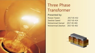
Three Phase Transformer
Presented by:
Rizwan Yaseen 2017-EE-432
Zeeshan Saeed 2017-EE-414
Muhammad Hamad 2017-EE-404
Muhammad Zeeshan 2017-EE-402
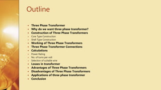
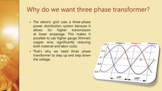
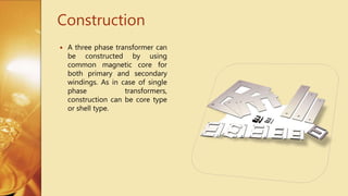
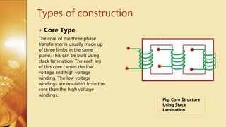
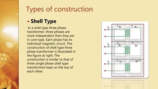
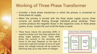
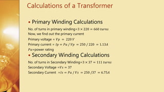
A three phase transformer is made of three sets of primary and secondary windings wound around the legs of a common iron core. It allows for higher transmission voltages using lower amperage wiring. The core can be constructed as either a core type or shell type configuration. A three phase transformer works by inducing secondary voltages from the three phase primary voltages to maintain the proper phase relationships for power distribution.


![transformhdhhjytbjguihgters_g_62[2].pptx](https://cdn.slidesharecdn.com/ss_thumbnails/transformersg622-250718173118-5265e8c2-thumbnail.jpg?width=640&height=640&fit=bounds)


![Chapter_3-Transformers[1]-1.pdf](https://cdn.slidesharecdn.com/ss_thumbnails/chapter3-transformers1-1-230622173423-be6efc48-thumbnail.jpg?width=640&height=640&fit=bounds)


