Download as PDF, PPTX
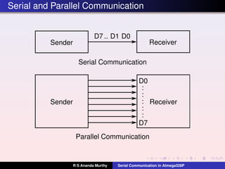
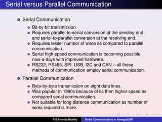
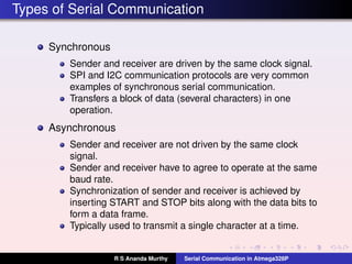
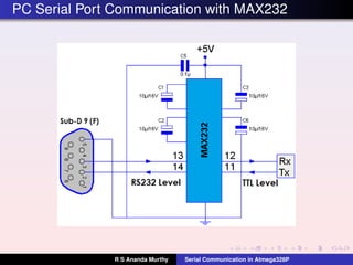
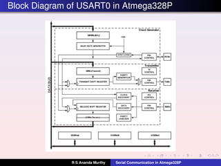
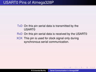
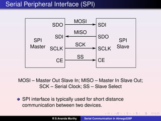
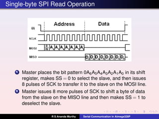
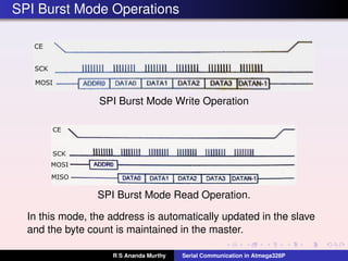

This document discusses serial communication in the Atmega328P microcontroller. It describes serial communication as bit-by-bit transmission that requires conversion between parallel and serial, and can operate over longer distances than parallel communication. The document outlines synchronous and asynchronous serial communication, common interface standards like RS-232, SPI, and serial communication protocols in the Atmega328P like USART and SPI.


![Communication_Protocols[2][1].pptx on protocoals](https://cdn.slidesharecdn.com/ss_thumbnails/communicationprotocols21-250429164707-38355411-thumbnail.jpg?width=640&height=640&fit=bounds)


