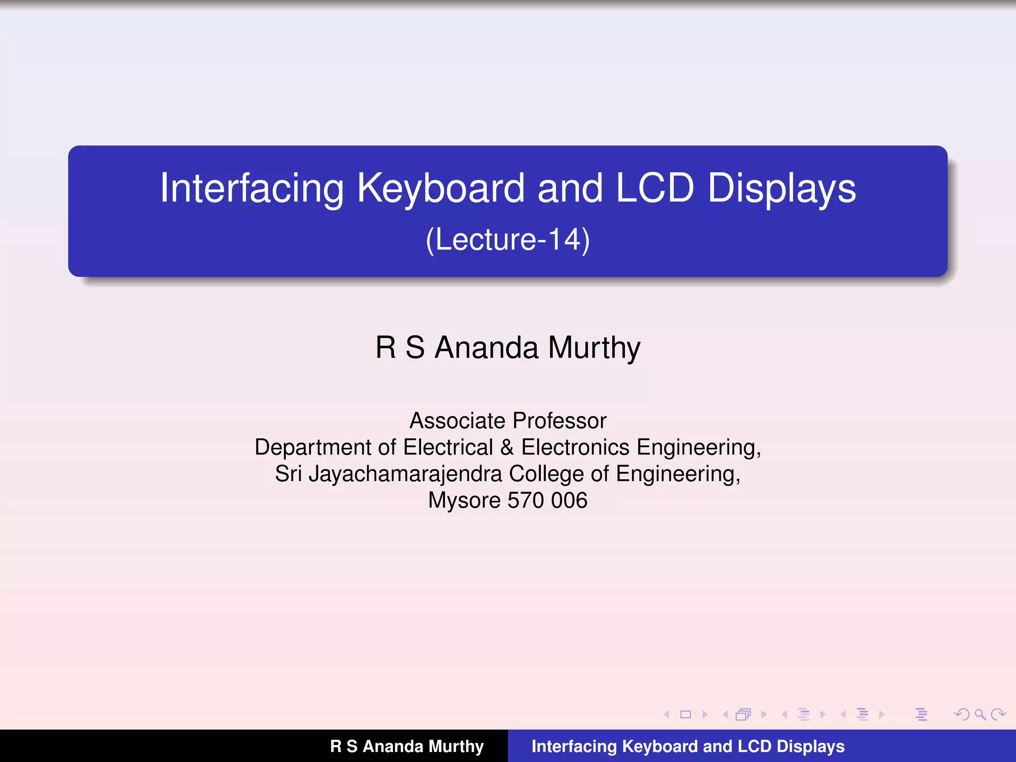
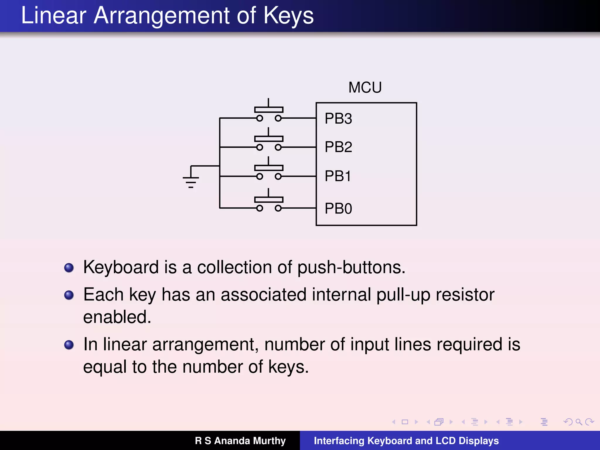
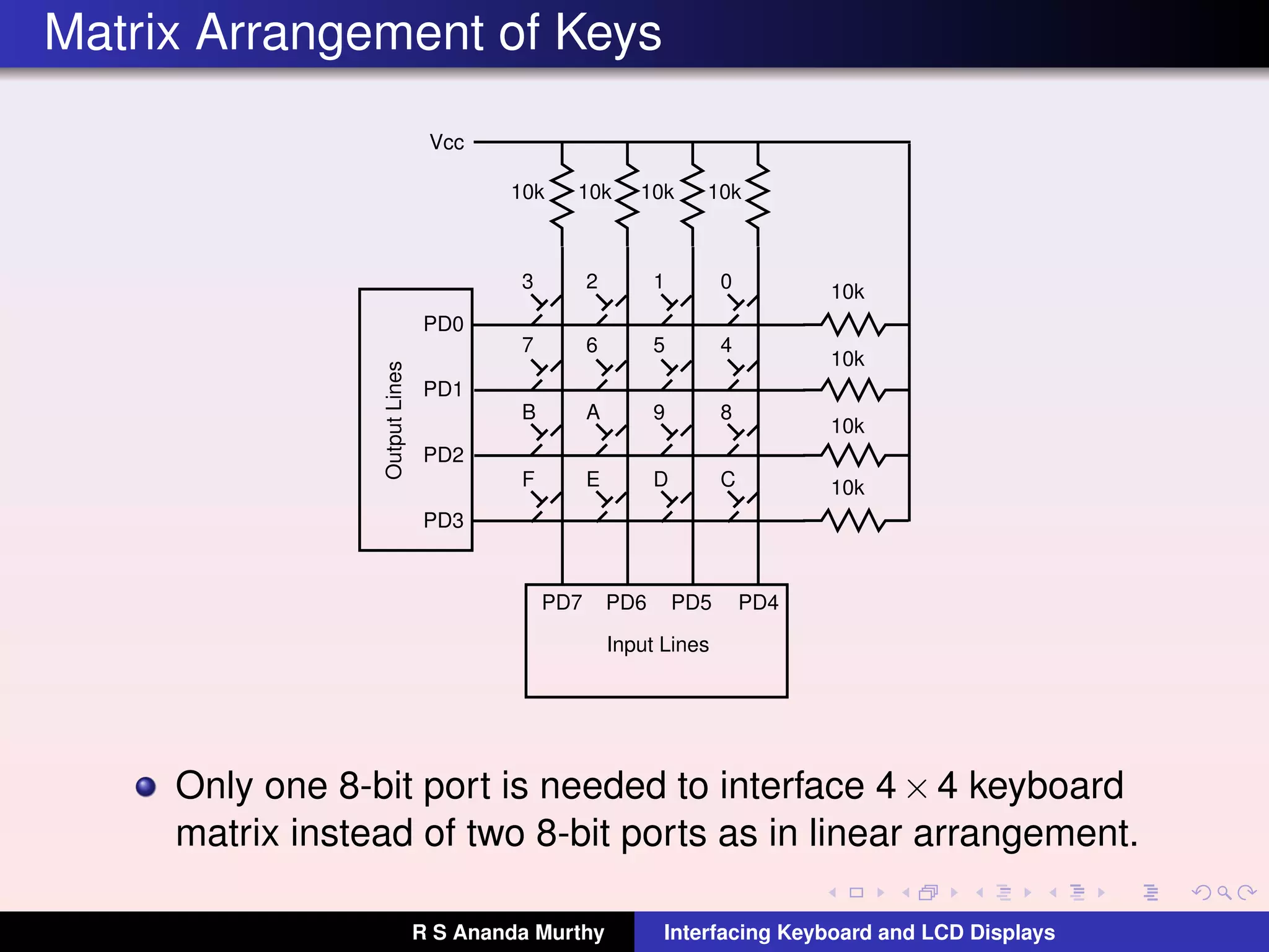
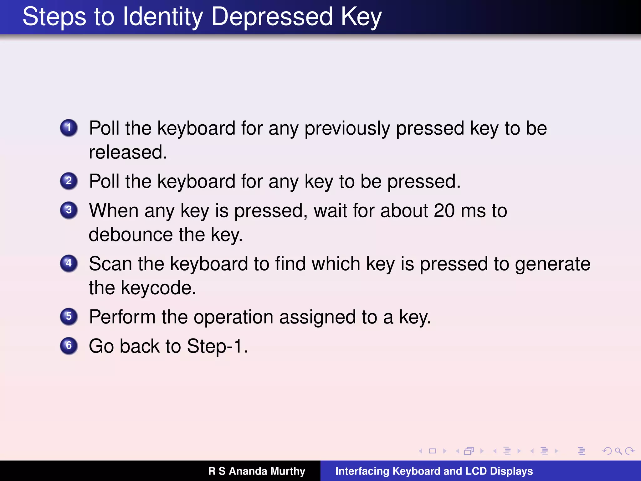
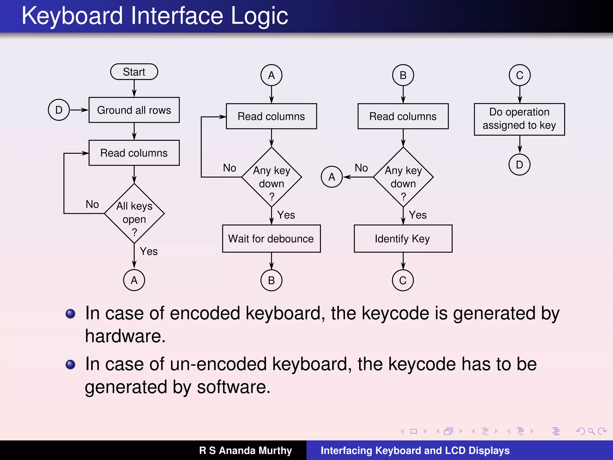
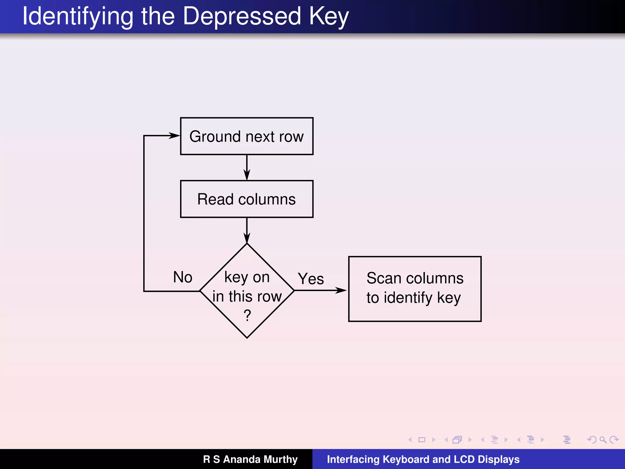
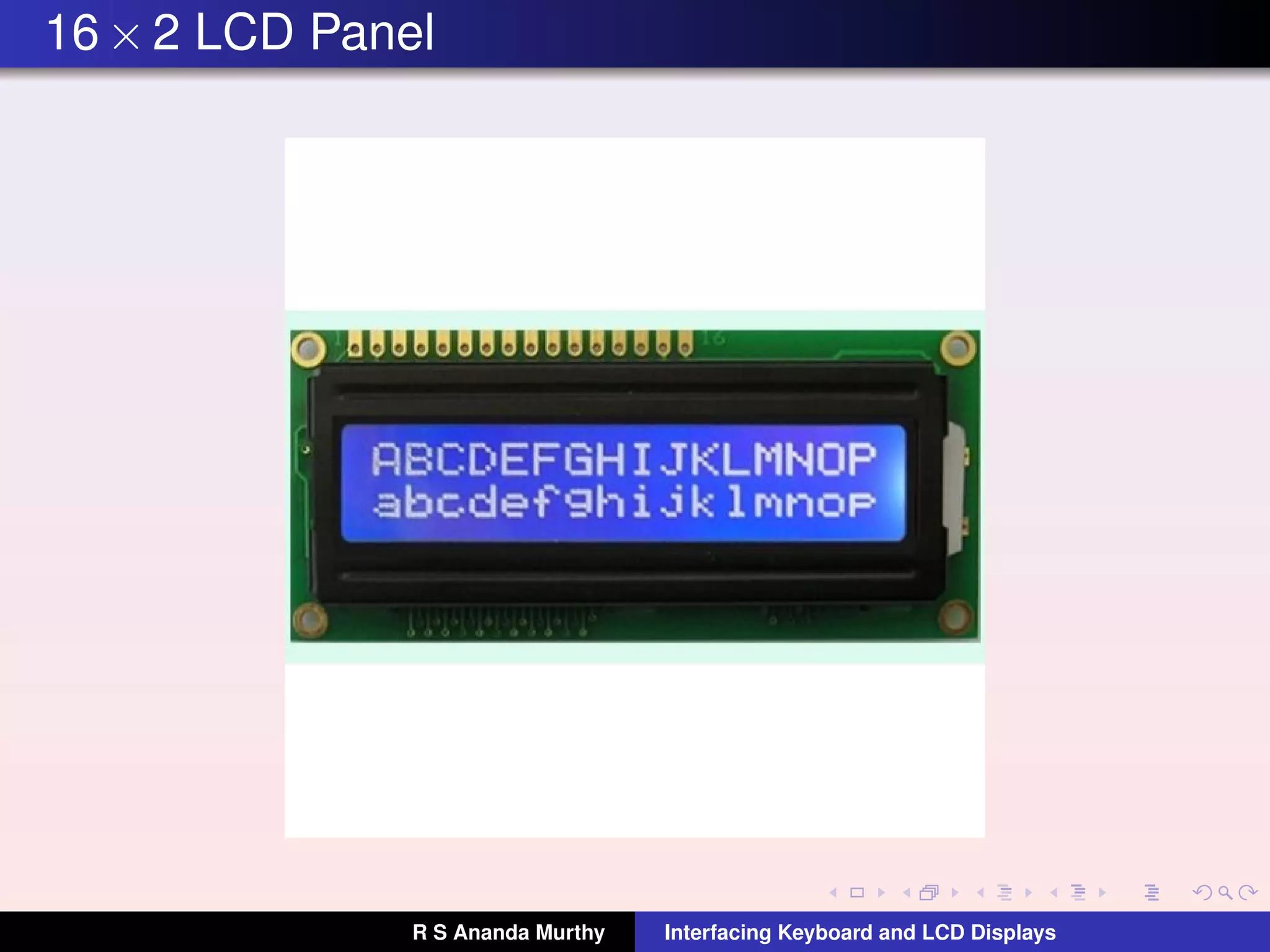
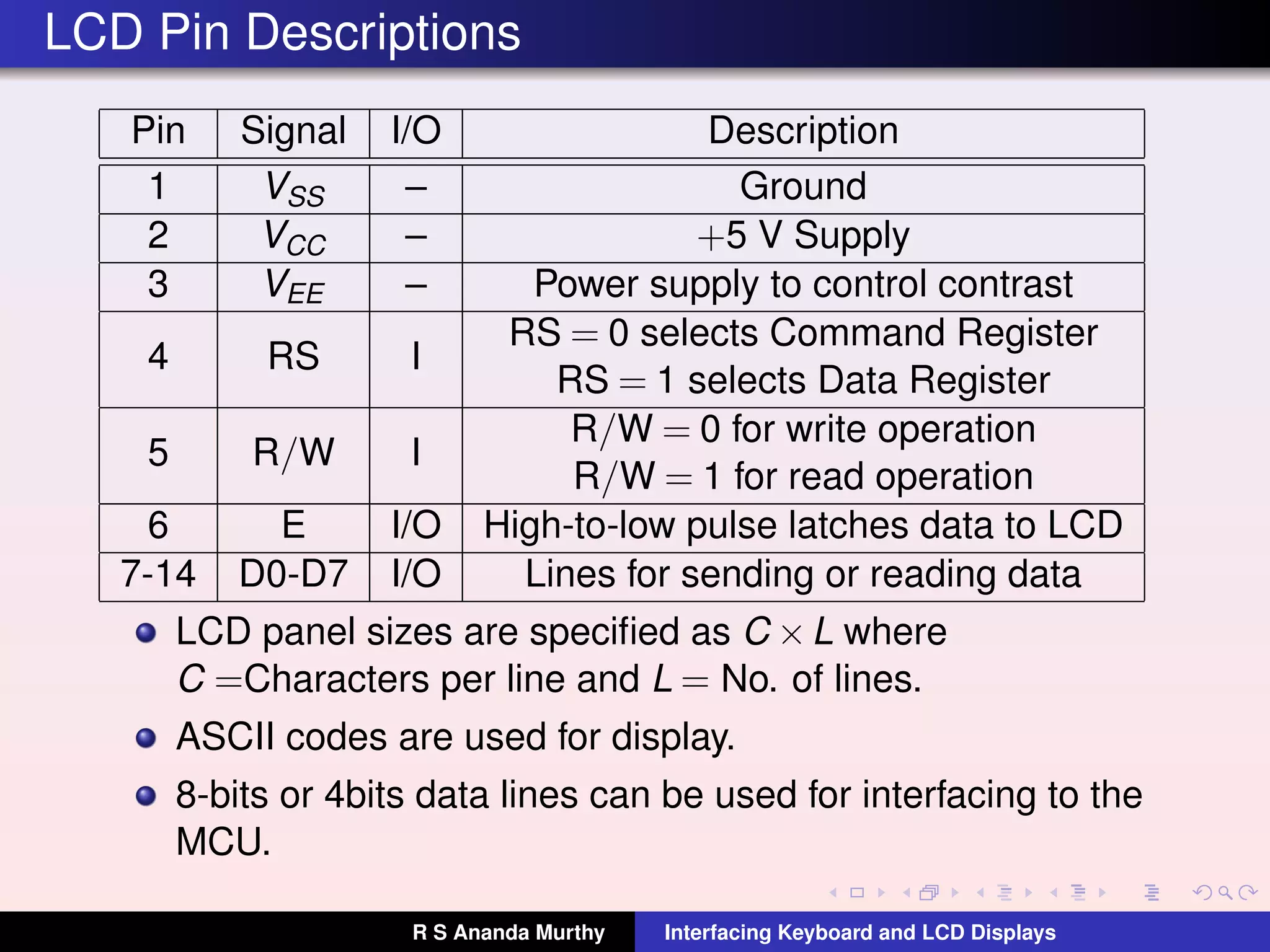
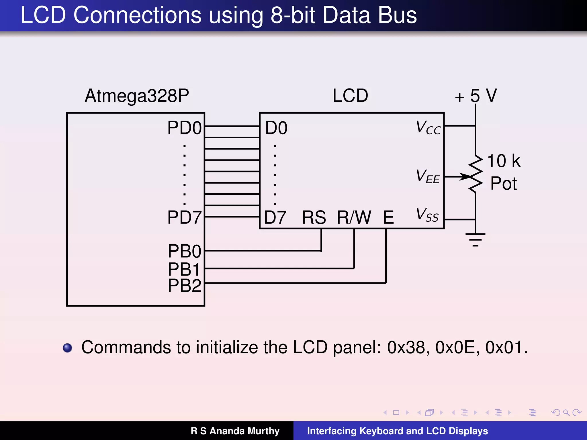
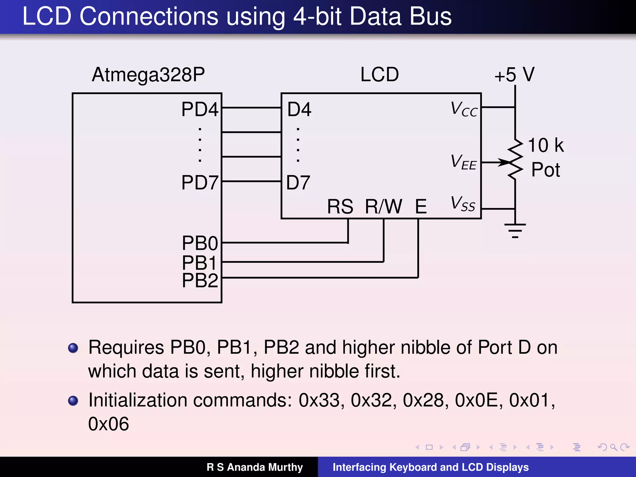
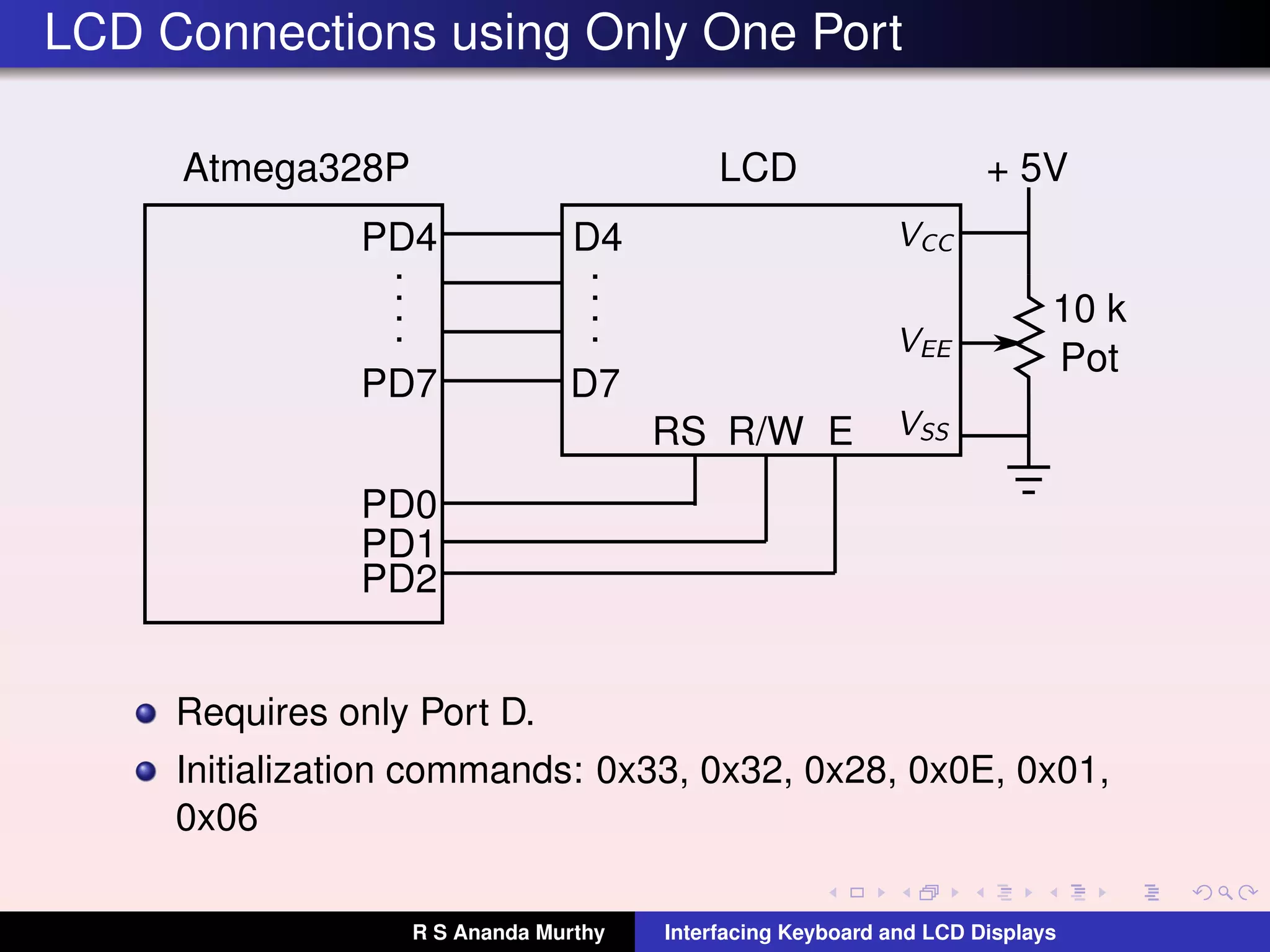
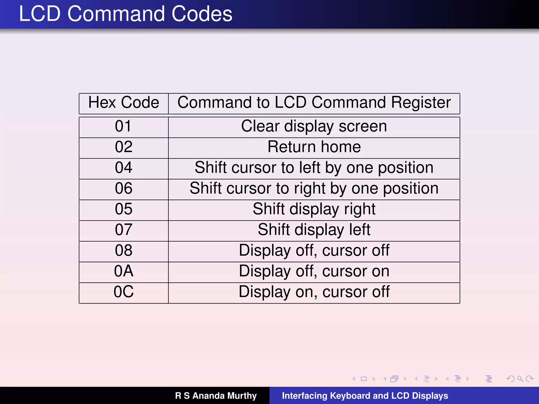
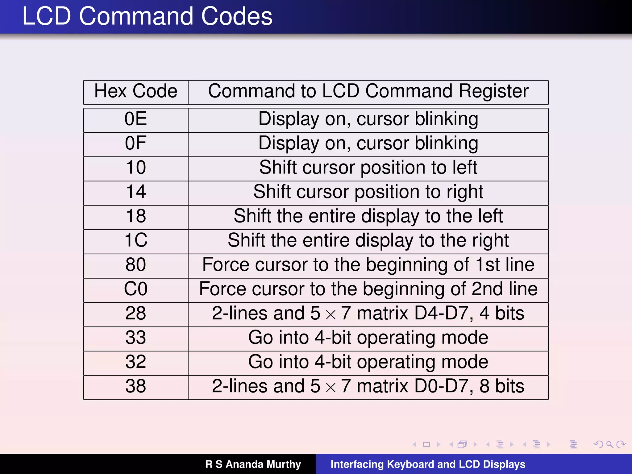
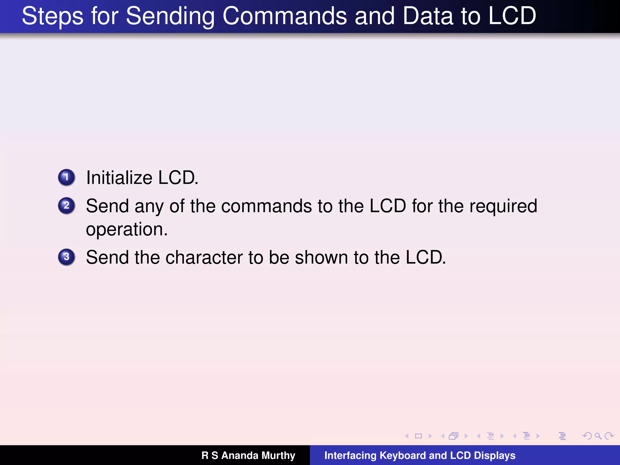
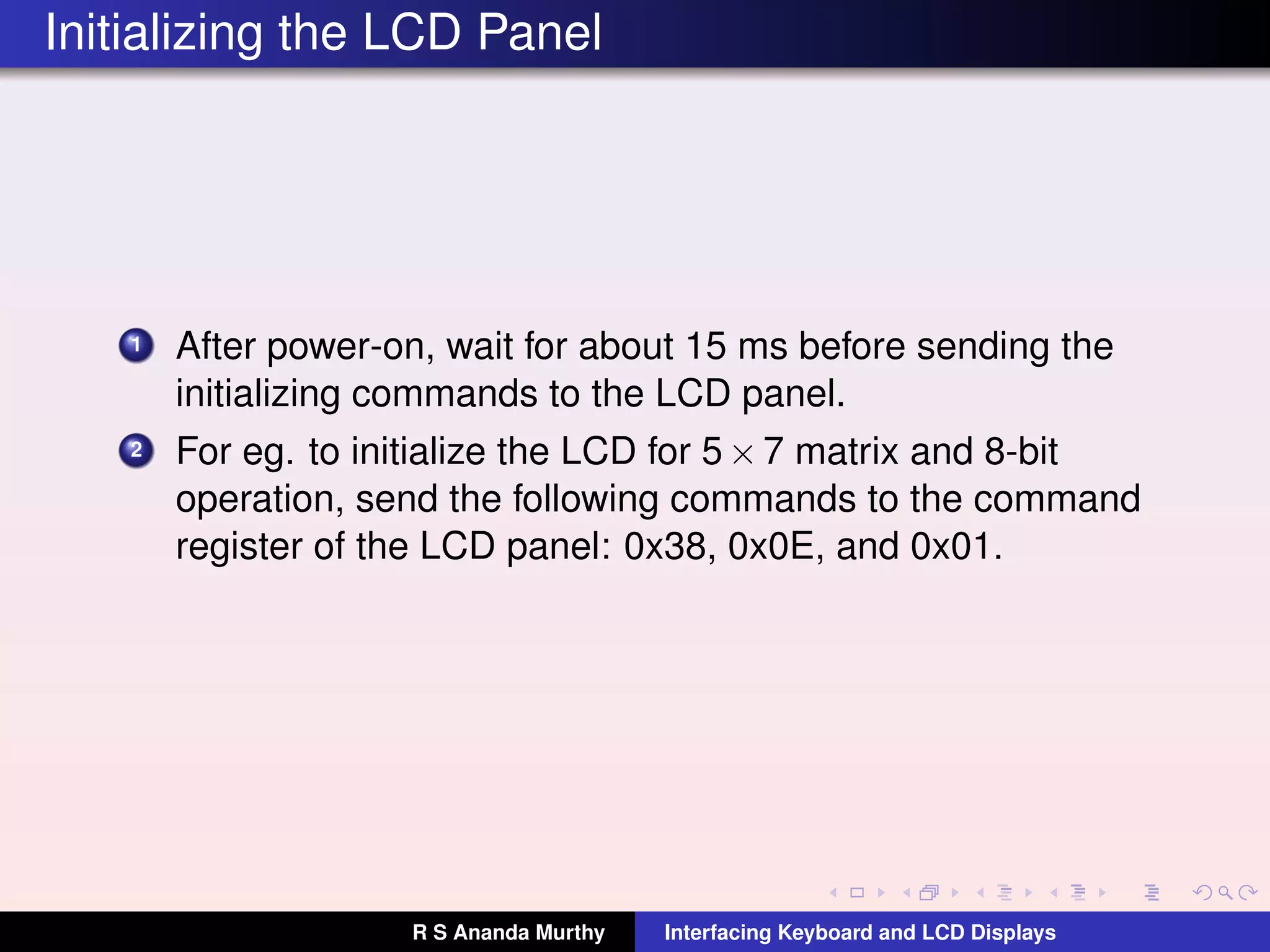
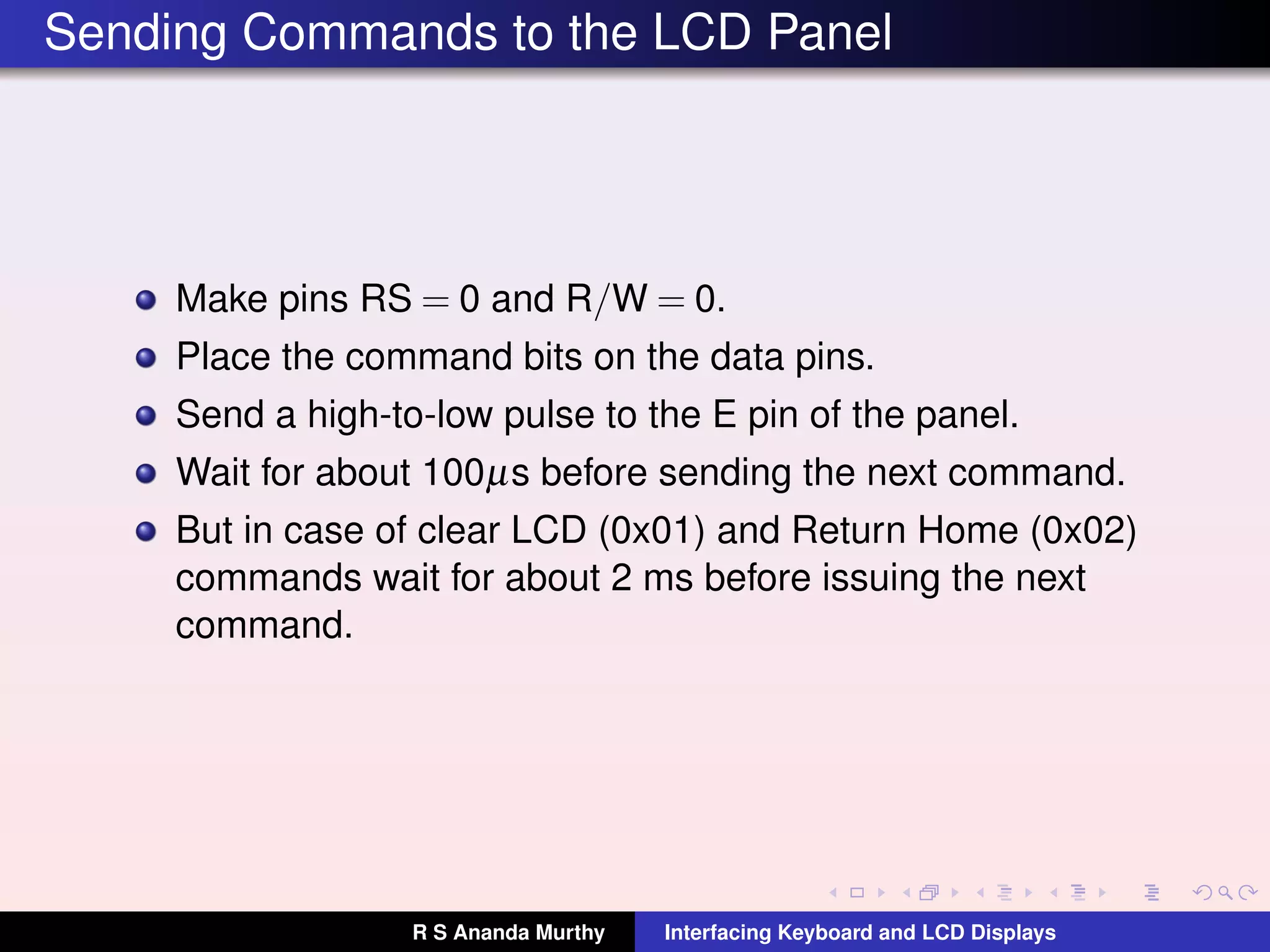
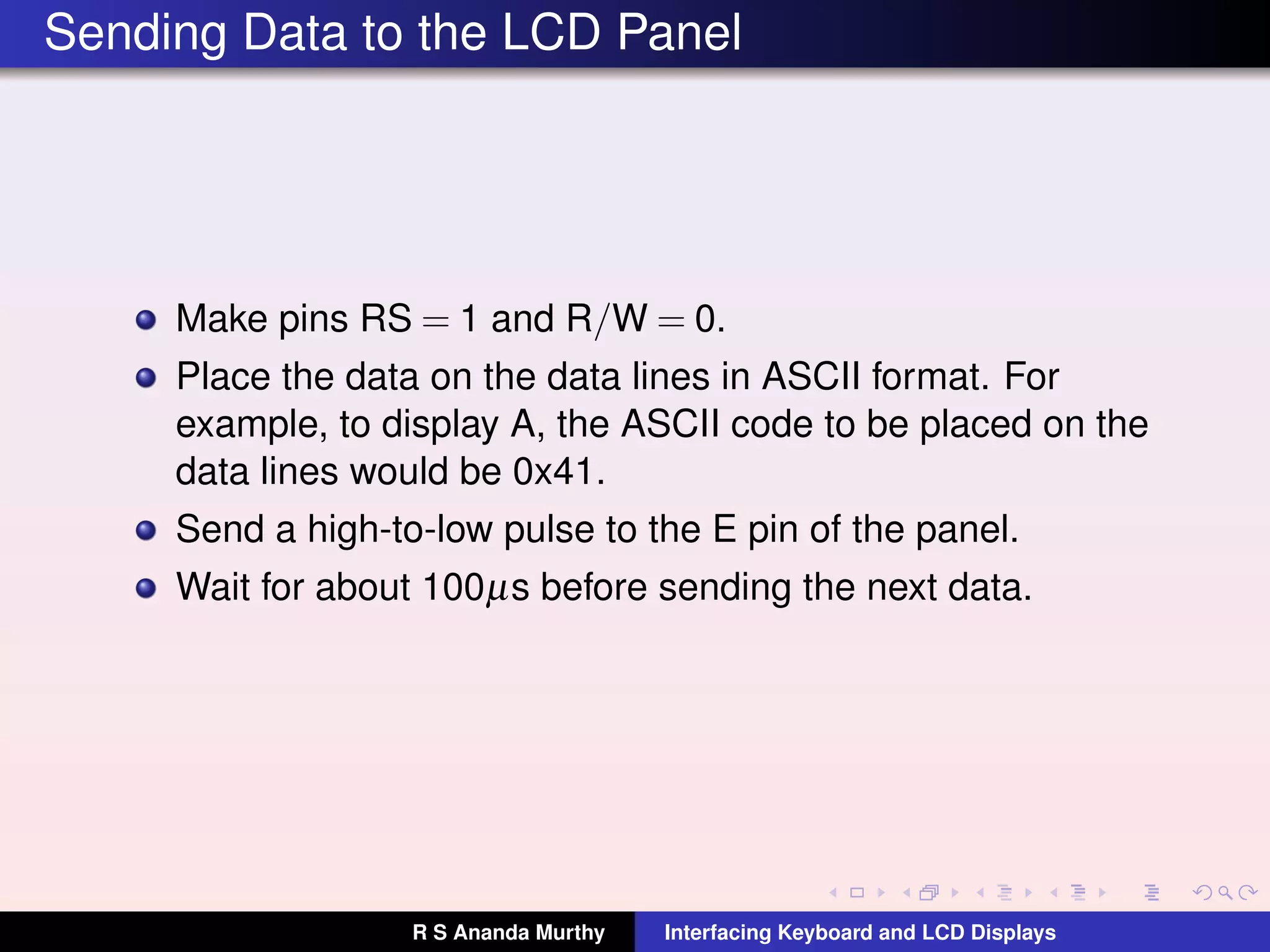
The document discusses interfacing keyboards and LCD displays. It describes both linear and matrix arrangements for keyboards and explains how to identify which key is pressed in a matrix. It also provides details on LCD displays, including pin descriptions and common commands. The steps to initialize an LCD and send commands and data are outlined.
Explains the difference between a microprocessor and a microcontroller, address, data, and control buses, word length and memory address space in a computer.
Customizable Microprocessor design on Nexys 3 Spartan FPGA BoardBharat Biyani
- Designed a 4 stage pipelined, 16-bit customizable microprocessor in VHDL which can execute instructions (direct & memory mapped addressing modes), handle interrupts (IVT based), communicate with IO devices including keyboard and VGA monitor and facilitates with a single port BLOCK RAM for Stack, Instruction , Data & IVT memory. Keyboard and VGA controller provides input-output interface gives user flexibility of keying in the instructions through Keyboard that is interfaced with Nexys 3 through USB 2.0; VGA interface to display the output. Keyboard and VGA controllers are also coded in VHDL.
- Implemented the VHDL code on Nexys 3 Spartan FPGA board which involved simulation, synthesis and bit file generation using Xilinx ISE,programming the FPGA with Digilent Adept.
- Employed the debug mode to make the design more user friendly
Codesign-Oriented Platform for Agile Internet of Things Prototype DevelopmentJonathan Ruiz de Garibay
The Internet of Things offers a growing market open to new products. To be able to take advantages of this opportunity companies need to be able to quickly create prototypes of their products. Given the difficulties that the development of embedded devices presents, both on the hardware and software parts, it is a necessity to create tools that ease this process. In this paper we present a codesing-oriented platform that will help developers to create their prototypes in an agile manner. The presented platform simplifies the usage and integration of standardized peripherals and reduces the complexity of the development process. We also present a prototype created using the platform, showcasing its capabilities.
Embedded system PPT that gives you complete information of Microcontroller & microprocessor.Pins of 8051.Interrupts as well as timer are also discussed.Addressing modes and real worldinterfacing with led,switch,lcd,seven segment as well as motor is also perform.
Lecture-3 : More Applications of Power Electronicsrsamurti
This is the third lecture on Power Electronics. This describes some more applications of Power Electronics to help the student understand the importance of Power Electronics in present and future technology.
ICStation team make this project about PS2 Keyboard read display system based on Arduino.It can be divided into 2 parts, the first part is that when you press the keys of letter or number only, the LCD 1602 will display the letter or number correspondingly. Another part is that when you press the keys of shift plus letter together, you will see that the LCD 1602 displays the capital letter.
Searching for Embedded Systems,VLSI,Matlab, PLC scada Training Institute in Hyderabad-Get the Best Embedded Systems,VLSI,Matlab, PLC scada Training with Real time Projects from Nanocdac. Register now for new batches Call Us-040 -23754144,+91- 9640648777
This presentation is all about interfacing of a character LCD with 8051 micro-controller. It discusses various LCD commands, LCD pin description and a simple LCD working code in assembly for interfacing.
The aim for this work is to understand how the LCD 1602A-1 (V 1.2) module
operates including commands and registers from the Dot Matrix Liquid Crystal Display
Controller/Driver.
Implementation in C and Assembly.
Similar to L14 kb-lcd-interfacing-with-atmega328 p (20)
NUMERICAL SIMULATIONS OF HEAT AND MASS TRANSFER IN CONDENSING HEAT EXCHANGERS...ssuser7dcef0
Power plants release a large amount of water vapor into the
atmosphere through the stack. The flue gas can be a potential
source for obtaining much needed cooling water for a power
plant. If a power plant could recover and reuse a portion of this
moisture, it could reduce its total cooling water intake
requirement. One of the most practical way to recover water
from flue gas is to use a condensing heat exchanger. The power
plant could also recover latent heat due to condensation as well
as sensible heat due to lowering the flue gas exit temperature.
Additionally, harmful acids released from the stack can be
reduced in a condensing heat exchanger by acid condensation. reduced in a condensing heat exchanger by acid condensation.
Condensation of vapors in flue gas is a complicated
phenomenon since heat and mass transfer of water vapor and
various acids simultaneously occur in the presence of noncondensable
gases such as nitrogen and oxygen. Design of a
condenser depends on the knowledge and understanding of the
heat and mass transfer processes. A computer program for
numerical simulations of water (H2O) and sulfuric acid (H2SO4)
condensation in a flue gas condensing heat exchanger was
developed using MATLAB. Governing equations based on
mass and energy balances for the system were derived to
predict variables such as flue gas exit temperature, cooling
water outlet temperature, mole fraction and condensation rates
of water and sulfuric acid vapors. The equations were solved
using an iterative solution technique with calculations of heat
and mass transfer coefficients and physical properties.
Water billing management system project report.pdfKamal Acharya
Our project entitled “Water Billing Management System” aims is to generate Water bill with all the charges and penalty. Manual system that is employed is extremely laborious and quite inadequate. It only makes the process more difficult and hard.
The aim of our project is to develop a system that is meant to partially computerize the work performed in the Water Board like generating monthly Water bill, record of consuming unit of water, store record of the customer and previous unpaid record.
We used HTML/PHP as front end and MYSQL as back end for developing our project. HTML is primarily a visual design environment. We can create a android application by designing the form and that make up the user interface. Adding android application code to the form and the objects such as buttons and text boxes on them and adding any required support code in additional modular.
MySQL is free open source database that facilitates the effective management of the databases by connecting them to the software. It is a stable ,reliable and the powerful solution with the advanced features and advantages which are as follows: Data Security.MySQL is free open source database that facilitates the effective management of the databases by connecting them to the software.
6th International Conference on Machine Learning & Applications (CMLA 2024)ClaraZara1
6th International Conference on Machine Learning & Applications (CMLA 2024) will provide an excellent international forum for sharing knowledge and results in theory, methodology and applications of on Machine Learning & Applications.
Using recycled concrete aggregates (RCA) for pavements is crucial to achieving sustainability. Implementing RCA for new pavement can minimize carbon footprint, conserve natural resources, reduce harmful emissions, and lower life cycle costs. Compared to natural aggregate (NA), RCA pavement has fewer comprehensive studies and sustainability assessments.
Forklift Classes Overview by Intella PartsIntella Parts
Discover the different forklift classes and their specific applications. Learn how to choose the right forklift for your needs to ensure safety, efficiency, and compliance in your operations.
For more technical information, visit our website https://intellaparts.com
Sachpazis:Terzaghi Bearing Capacity Estimation in simple terms with Calculati...Dr.Costas Sachpazis
Terzaghi's soil bearing capacity theory, developed by Karl Terzaghi, is a fundamental principle in geotechnical engineering used to determine the bearing capacity of shallow foundations. This theory provides a method to calculate the ultimate bearing capacity of soil, which is the maximum load per unit area that the soil can support without undergoing shear failure. The Calculation HTML Code included.
Final project report on grocery store management system..pdfKamal Acharya
In today’s fast-changing business environment, it’s extremely important to be able to respond to client needs in the most effective and timely manner. If your customers wish to see your business online and have instant access to your products or services.
Online Grocery Store is an e-commerce website, which retails various grocery products. This project allows viewing various products available enables registered users to purchase desired products instantly using Paytm, UPI payment processor (Instant Pay) and also can place order by using Cash on Delivery (Pay Later) option. This project provides an easy access to Administrators and Managers to view orders placed using Pay Later and Instant Pay options.
In order to develop an e-commerce website, a number of Technologies must be studied and understood. These include multi-tiered architecture, server and client-side scripting techniques, implementation technologies, programming language (such as PHP, HTML, CSS, JavaScript) and MySQL relational databases. This is a project with the objective to develop a basic website where a consumer is provided with a shopping cart website and also to know about the technologies used to develop such a website.
This document will discuss each of the underlying technologies to create and implement an e- commerce website.
Hierarchical Digital Twin of a Naval Power SystemKerry Sado
A hierarchical digital twin of a Naval DC power system has been developed and experimentally verified. Similar to other state-of-the-art digital twins, this technology creates a digital replica of the physical system executed in real-time or faster, which can modify hardware controls. However, its advantage stems from distributing computational efforts by utilizing a hierarchical structure composed of lower-level digital twin blocks and a higher-level system digital twin. Each digital twin block is associated with a physical subsystem of the hardware and communicates with a singular system digital twin, which creates a system-level response. By extracting information from each level of the hierarchy, power system controls of the hardware were reconfigured autonomously. This hierarchical digital twin development offers several advantages over other digital twins, particularly in the field of naval power systems. The hierarchical structure allows for greater computational efficiency and scalability while the ability to autonomously reconfigure hardware controls offers increased flexibility and responsiveness. The hierarchical decomposition and models utilized were well aligned with the physical twin, as indicated by the maximum deviations between the developed digital twin hierarchy and the hardware.
We have compiled the most important slides from each speaker's presentation. This year’s compilation, available for free, captures the key insights and contributions shared during the DfMAy 2024 conference.
Fundamentals of Electric Drives and its applications.pptx
L14 kb-lcd-interfacing-with-atmega328 p
1. Interfacing Keyboard and LCD Displays
(Lecture-14)
R S Ananda Murthy
Associate Professor
Department of Electrical & Electronics Engineering,
Sri Jayachamarajendra College of Engineering,
Mysore 570 006
R S Ananda Murthy Interfacing Keyboard and LCD Displays
2. Linear Arrangement of Keys
MCU
PB0
PB1
PB2
PB3
Keyboard is a collection of push-buttons.
Each key has an associated internal pull-up resistor
enabled.
In linear arrangement, number of input lines required is
equal to the number of keys.
R S Ananda Murthy Interfacing Keyboard and LCD Displays
3. Matrix Arrangement of Keys
When large number of keys are to be interfaced, linear
arrangement is not preferred since the number of input
lines required will be more.
In matrix arrangement, a key is connected between a row
and a column.
If there are R rows and C columns, then, the maximum
number of keys in the matrix could be N = R ×C and the
number of lines required for interfacing would be R +C and
not N.
R S Ananda Murthy Interfacing Keyboard and LCD Displays
4. Matrix Arrangement of Keys
0123
4567
89AB
CDEF
10k 10k 10k 10k
10k
10k
10k
10k
PD4PD5PD6PD7
Input Lines
PD3
PD2
PD1
PD0
OutputLines
Vcc
Only one 8-bit port is needed to interface 4×4 keyboard
matrix instead of two 8-bit ports as in linear arrangement.
R S Ananda Murthy Interfacing Keyboard and LCD Displays
5. Steps to Identity Depressed Key
1 Poll the keyboard for any previously pressed key to be
released.
2 Poll the keyboard for any key to be pressed.
3 When any key is pressed, wait for about 20 ms to
debounce the key.
4 Scan the keyboard to find which key is pressed to generate
the keycode.
5 Perform the operation assigned to a key.
6 Go back to Step-1.
R S Ananda Murthy Interfacing Keyboard and LCD Displays
6. Keyboard Interface Logic
Start
Ground all rows
Read columns
All keys
open
?
No
Yes
A
A
Read columns
Any key
down
?
No
Yes
Wait for debounce
B
B
Read columns
Any key
down
?
No
Yes
A
C
Identify Key
C
Do operation
assigned to key
D
D
In case of encoded keyboard, the keycode is generated by
hardware.
In case of un-encoded keyboard, the keycode has to be
generated by software.
R S Ananda Murthy Interfacing Keyboard and LCD Displays
7. Identifying the Depressed Key
Ground next row
Read columns
key on
in this row
?
No Yes Scan columns
to identify key
R S Ananda Murthy Interfacing Keyboard and LCD Displays
8. 16×2 LCD Panel
R S Ananda Murthy Interfacing Keyboard and LCD Displays
9. Advantages of LCD Panels
LCD panels are becoming cheaper.
LCD panels can display numbers, characters, and graphics
unlike LEDs which are limited to numbers and few
characters.
Since LCDs have an in-built refreshing controller the MCU
need not refresh the display as in the case of LEDs.
LCDs are easy to program since ASCII codes are used for
display by LCDs instead of 7-segment codes used for
LEDs.
LCDs consume less power.
R S Ananda Murthy Interfacing Keyboard and LCD Displays
10. LCD Pin Descriptions
Pin Signal I/O Description
1 VSS – Ground
2 VCC – +5 V Supply
3 VEE – Power supply to control contrast
4 RS I
RS = 0 selects Command Register
RS = 1 selects Data Register
5 R/W I
R/W = 0 for write operation
R/W = 1 for read operation
6 E I/O High-to-low pulse latches data to LCD
7-14 D0-D7 I/O Lines for sending or reading data
LCD panel sizes are specified as C ×L where
C =Characters per line and L = No. of lines.
ASCII codes are used for display.
8-bits or 4bits data lines can be used for interfacing to the
MCU.
R S Ananda Murthy Interfacing Keyboard and LCD Displays
11. LCD Connections using 8-bit Data Bus
10 k
Pot
PD0
PD7
.
.
.
.
.
.
.
Atmega328P LCD
D0
.
.
.
.
.
.
.
D7
PB0
PB1
PB2
RS R/W E
+ 5 V
Commands to initialize the LCD panel: 0x38, 0x0E, 0x01.
R S Ananda Murthy Interfacing Keyboard and LCD Displays
12. LCD Connections using 4-bit Data Bus
10 k
Pot
PD4
PD7
.
.
.
.
Atmega328P LCD
D4
.
.
.
.
D7
PB0
PB1
PB2
RS R/W E
+5 V
Requires PB0, PB1, PB2 and higher nibble of Port D on
which data is sent, higher nibble first.
Initialization commands: 0x33, 0x32, 0x28, 0x0E, 0x01,
0x06
R S Ananda Murthy Interfacing Keyboard and LCD Displays
13. LCD Connections using Only One Port
10 k
Pot
PD4
PD7
.
.
.
.
Atmega328P LCD
D4
.
.
.
.
D7
PD0
PD1
PD2
RS R/W E
+ 5V
Requires only Port D.
Initialization commands: 0x33, 0x32, 0x28, 0x0E, 0x01,
0x06
R S Ananda Murthy Interfacing Keyboard and LCD Displays
14. LCD Command Codes
Hex Code Command to LCD Command Register
01 Clear display screen
02 Return home
04 Shift cursor to left by one position
06 Shift cursor to right by one position
05 Shift display right
07 Shift display left
08 Display off, cursor off
0A Display off, cursor on
0C Display on, cursor off
R S Ananda Murthy Interfacing Keyboard and LCD Displays
15. LCD Command Codes
Hex Code Command to LCD Command Register
0E Display on, cursor blinking
0F Display on, cursor blinking
10 Shift cursor position to left
14 Shift cursor position to right
18 Shift the entire display to the left
1C Shift the entire display to the right
80 Force cursor to the beginning of 1st line
C0 Force cursor to the beginning of 2nd line
28 2-lines and 5×7 matrix D4-D7, 4 bits
33 Go into 4-bit operating mode
32 Go into 4-bit operating mode
38 2-lines and 5×7 matrix D0-D7, 8 bits
R S Ananda Murthy Interfacing Keyboard and LCD Displays
16. Steps for Sending Commands and Data to LCD
1 Initialize LCD.
2 Send any of the commands to the LCD for the required
operation.
3 Send the character to be shown to the LCD.
R S Ananda Murthy Interfacing Keyboard and LCD Displays
17. Initializing the LCD Panel
1 After power-on, wait for about 15 ms before sending the
initializing commands to the LCD panel.
2 For eg. to initialize the LCD for 5×7 matrix and 8-bit
operation, send the following commands to the command
register of the LCD panel: 0x38, 0x0E, and 0x01.
R S Ananda Murthy Interfacing Keyboard and LCD Displays
18. Sending Commands to the LCD Panel
Make pins RS = 0 and R/W = 0.
Place the command bits on the data pins.
Send a high-to-low pulse to the E pin of the panel.
Wait for about 100µs before sending the next command.
But in case of clear LCD (0x01) and Return Home (0x02)
commands wait for about 2 ms before issuing the next
command.
R S Ananda Murthy Interfacing Keyboard and LCD Displays
19. Sending Data to the LCD Panel
Make pins RS = 1 and R/W = 0.
Place the data on the data lines in ASCII format. For
example, to display A, the ASCII code to be placed on the
data lines would be 0x41.
Send a high-to-low pulse to the E pin of the panel.
Wait for about 100µs before sending the next data.
R S Ananda Murthy Interfacing Keyboard and LCD Displays
20. License
This work is licensed under a
Creative Commons Attribution 4.0 International License.
R S Ananda Murthy Interfacing Keyboard and LCD Displays