Download to read offline
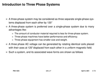

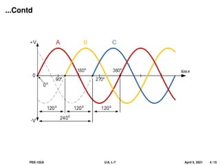
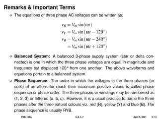

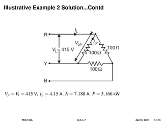

This document covers the fundamentals of three-phase electrical systems, highlighting the advantages over single-phase systems, such as reduced conductor material and improved machine efficiency. It explains key concepts including balanced systems, phase sequence, and the relationships between voltage, current, and power in three-phase systems. Additionally, it provides illustrative examples of calculations related to phase and line currents, as well as power drawn from the source.