Downloaded 157 times

![Target building
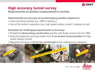
Plumbing Error
α
β1
β2
β3
q
B S
QL
Real direction with plumbing error q
Theoretical direction without plumbing error
Tunnel
length [m]
Lateral deflection
Plumb error: 1 mm
Base length: 10 m
Lateral deflection
Plumb error: 1,5 mm
Base length: 8 m
300 4,2 cm 8,0 cm
1.000 14,1 cm 26,5 cm
10.000 141,4 cm 265,2 cm
β1
β2
β3
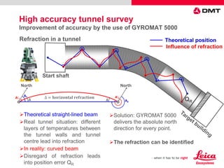
Start shaft
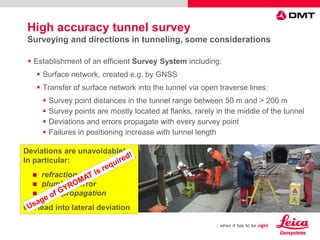
High accuracy tunnel survey
Improvement of accuracy by the use of GYROMAT 5000](https://image.slidesharecdn.com/dmtgyromat5000hxgnlive2014cddmt-140721041436-phpapp02/85/Gyromat-in-tunnelling-practice-10-320.jpg)
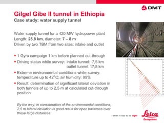
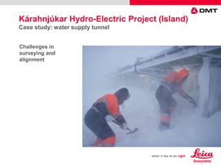
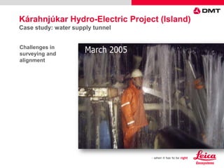
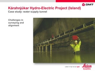
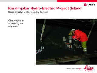
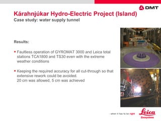
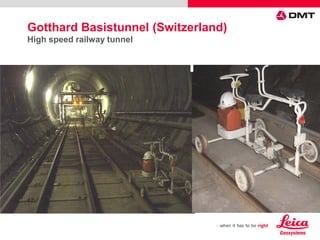
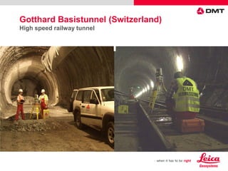
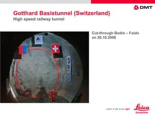
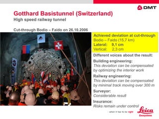
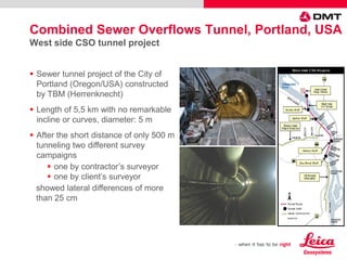
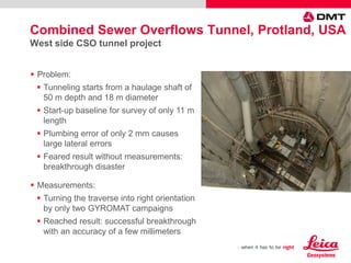
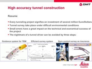

The document discusses the DMT Gyromat 5000, an advanced gyroscope designed for high precision surveying, particularly in tunnel construction. It highlights the importance of accurate measurements in tunneling projects and provides case studies demonstrating the Gyromat 5000's effectiveness in reducing deviations during such surveys. The Gyromat 5000, combined with high-end Leica total stations, minimizes errors caused by environmental conditions, ensuring enhanced accuracy in complex tunneling scenarios.


![[Deck] What's New in Spark-Iceberg Integration via DSV2.pptx](https://cdn.slidesharecdn.com/ss_thumbnails/deckwhatsnewinspark-icebergintegrationviadsv2-260210005337-25955b12-thumbnail.jpg?width=640&height=640&fit=bounds)


