PRESENTATION ABOUT TOTAL STATION: PRICIPLES AND USAGE
1.
Total Stations
Prof. MohammedTaleb Obaidat
03/08/2025 1
Total Stations
Prof. Mohammed Taleb Obaidat
Civil Engineering Department
Jordan University of Science and Technology (JUST)
Irbid-Jordan
E-mail: mobaidat@just.edu.jo
Home-Page: www.just.edu.jo/mobaidat
2.
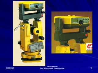
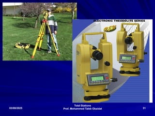
TOTAL STATION
Basic Principle
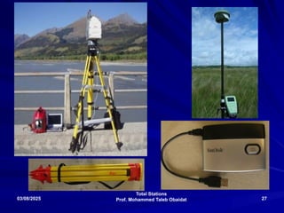
Atotal station integrates the functions of a
theodolite for measuring angles, an EDM for
measuring distances, digital data and a data
recorder. Examples of total stations are the
Sokkia Set4C and the Geodimeter 400 series.
All total stations have similar constructional
features regardless of their age or level of
technology, and all perform basically the same
functions.
3.
Total Stations
Prof. MohammedTaleb Obaidat
03/08/2025 3
Introduction:
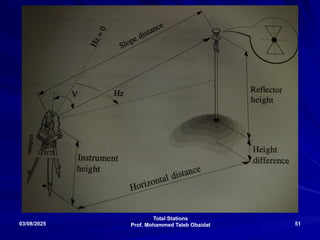
Measurements Capabilities:
Distances (H, V , S)
Angles (H, V)
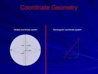
3-D Coordinates: with the aid
of trigonometry the angles and distances
may be used to calculate the coordinates of
actual positions (X, Y, and Z or northing,
easting and elevation) of surveyed points,
or the position of the instrument from
known points, in absolute terms.
4.
Total Stations
Prof. MohammedTaleb Obaidat
03/08/2025 4
The data may be downloaded from the theodolite
to a computer and application software will
generate a map of the surveyed area.
Some total stations also have a GPS
The best quality total stations are capable of
measuring angles down to 0.5 arc-second.
Inexpensive "construction grade" total stations
can generally measure angles to 5 or 10 arc-
seconds.
Measurement of distance is accomplished with a
modulated microwave or infrared carrier signal,
generated by a small solid-state emitter within the
instrument's optical path, and bounced off of the
object to be measured.
5.
Total Stations
Prof. MohammedTaleb Obaidat
03/08/2025 5
Most total stations use a purpose-built glass
prism as the reflector for the EDM signal, and
can measure distances out to a few
kilometers, but some instruments are
"reflectorless", and can measure distances to
any object that is reasonably light in color,
out to a few hundred meters.
The typical Total Station EDM can measure
distances accurate to about 0.1 millimeter or
1/1000-foot, but most land surveying
applications only take distance
measurements to 1.0 mm or 1/100-foot.
6.
Total Stations
Prof. MohammedTaleb Obaidat
03/08/2025 6
Some modern machines are 'robotic'
allowing the operator to control the machine
from a distance via remote control. This
eliminates the need for an assistant staff
member to hold the reflector prism over the
point to be measured. The operator holds
the reflector him/herself and controls the
machine from the observed point.
7.
7
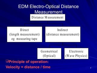
EDM Electro-Optical Distance
Measurement
Direct
(lengthmeasurement)
eg measuring tape
Geometrical
(Optical)
Electronic
(W ave Physics)
Indirect
(distance measurement)
Distance M easurement
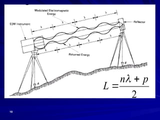
Principle of operation:
Velocity = distance / time
8.
8
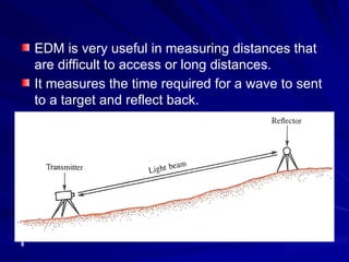
EDM is veryuseful in measuring distances that
are difficult to access or long distances.
It measures the time required for a wave to sent
to a target and reflect back.
9.
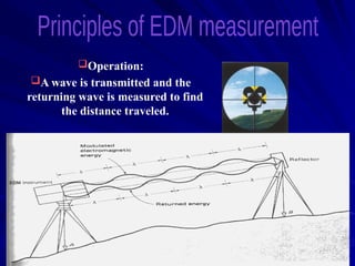
Operation:
A wave istransmitted and the
returning wave is measured to find
the distance traveled.
11
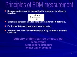
Distances determined bycalculating the number of wavelengths
travelled.
Errors are generally small and insignificant for short distances.
For longer distances they canbe more important.
Errors can be accounted for manually, or by the EDM if it has the
capability.
Velocity of light can be affected by:
Temperature
Atmospheric pressure
Water vapor content
12.
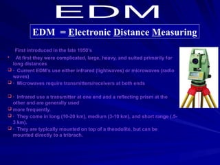
· First introducedin the late 1950’s
• At first they were complicated, large, heavy, and suited primarily for
long distances
· Current EDM’s use either infrared (lightwaves) or microwaves (radio
waves)
· Microwaves require transmitters/receivers at both ends
· Infrared use a transmitter at one end and a reflecting prism at the
other and are generally used
more frequently.
· They come in long (10-20 km), medium (3-10 km), and short range (.5-
3 km).
· They are typically mounted on top of a theodolite, but can be
mounted directly to a tribrach.
EDM = Electronic Distance Measuring
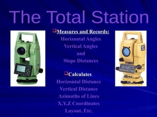
Measures and Records:
HorizontalAngles
Vertical Angles
and
Slope Distances
Calculates:
Horizontal Distance
Vertical Distance
Azimuths of Lines
X,Y,Z Coordinates
Layout, Etc.
15.
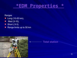
15
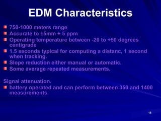
EDM Characteristics
750-1000 metersrange
Accurate to ±5mm + 5 ppm
Operating temperature between -20 to +50 degrees
centigrade
1.5 seconds typical for computing a distanc, 1 second
when tracking.
Slope reduction either manual or automatic.
Some average repeated measurements.
Signal attenuation.
battery operated and can perform between 350 and 1400
measurements.
16.
16
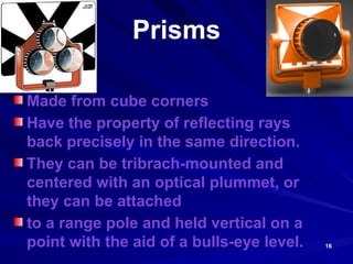
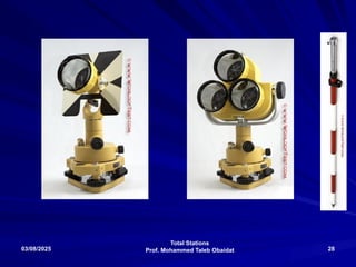
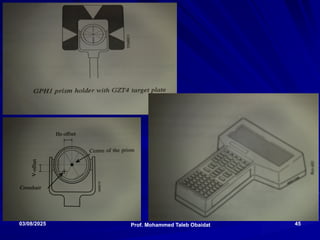
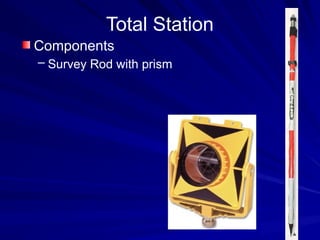
Prisms
Made from cubecorners
Have the property of reflecting rays
back precisely in the same direction.
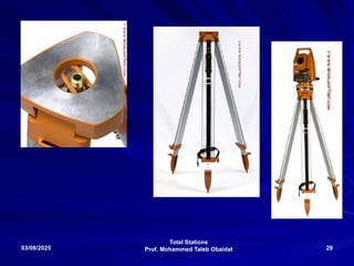
They can be tribrach-mounted and
centered with an optical plummet, or
they can be attached
to a range pole and held vertical on a
point with the aid of a bulls-eye level.
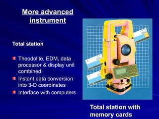
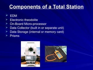
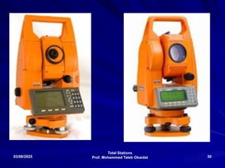
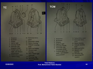
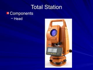
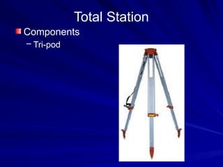
Components of aTotal Station
EDM
Electronic theodolite
On-Board Micro-processor
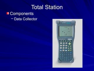
Data Collector (built in or separate unit)
Data Storage (internal or memory card)
Prisms
23.
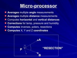
Micro-processor
Averages multiple anglemeasurements
Averages multiple distance measurements
Computes horizontal and vertical distances
Corrections for temp, pressure and humidity
Computes inverses, polars, resections
Computes X, Y and Z coordinates
P
A
B
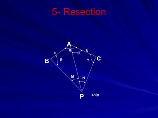
“RESECTION”
24.
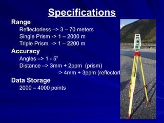
Specifications
Range
Reflectorless –> 3– 70 meters
Single Prism -> 1 – 2000 m
Triple Prism -> 1 – 2200 m
Accuracy
Angles –> 1 - 5”
Distance –> 3mm + 2ppm (prism)
-> 4mm + 3ppm (reflectorless)
Data Storage
2000 – 4000 points
25.
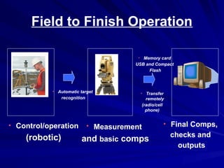
Field to FinishOperation
• Control/operation
(robotic)
• Measurement
and basic comps
• Final Comps,
checks and
outputs
• Transfer
remotely
(radio/cell
phone)
• Memory card
USB and Compact
Flash
• Automatic target
recognition
26.
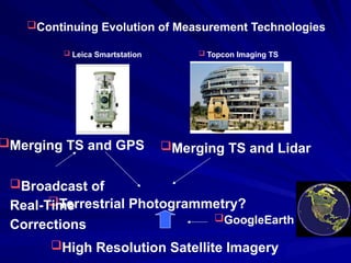
Continuing Evolution ofMeasurement Technologies
Leica Smartstation Topcon Imaging TS
Merging TS and GPS Merging TS and Lidar
Terrestrial Photogrammetry?
High Resolution Satellite Imagery
GoogleEarth
Broadcast of
Real-Time
Corrections
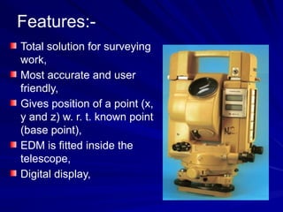
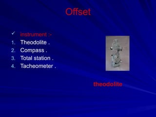
Features:-
Total solution forsurveying
work,
Most accurate and user
friendly,
Gives position of a point (x,
y and z) w. r. t. known point
(base point),
EDM is fitted inside the
telescope,
Digital display,
33.
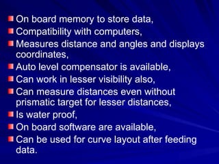
On board memoryto store data,
Compatibility with computers,
Measures distance and angles and displays
coordinates,
Auto level compensator is available,
Can work in lesser visibility also,
Can measure distances even without
prismatic target for lesser distances,
Is water proof,
On board software are available,
Can be used for curve layout after feeding
data.
34.
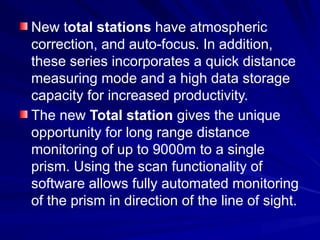
New total stationshave atmospheric
correction, and auto-focus. In addition,
these series incorporates a quick distance
measuring mode and a high data storage
capacity for increased productivity.
The new Total station gives the unique
opportunity for long range distance
monitoring of up to 9000m to a single
prism. Using the scan functionality of
software allows fully automated monitoring
of the prism in direction of the line of sight.
35.
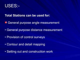
USES:-
Total Stations canbe used for:
General purpose angle measurement
• General purpose distance measurement
• Provision of control surveys
• Contour and detail mapping
• Setting out and construction work
36.
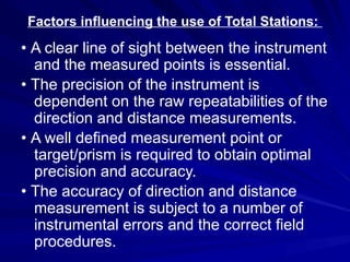
Factors influencing theuse of Total Stations:
• A clear line of sight between the instrument
and the measured points is essential.
• The precision of the instrument is
dependent on the raw repeatabilities of the
direction and distance measurements.
• A well defined measurement point or
target/prism is required to obtain optimal
precision and accuracy.
• The accuracy of direction and distance
measurement is subject to a number of
instrumental errors and the correct field
procedures.
37.
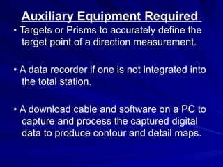
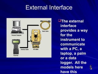
Auxiliary Equipment Required
•Targets or Prisms to accurately define the
target point of a direction measurement.
• A data recorder if one is not integrated into
the total station.
• A download cable and software on a PC to
capture and process the captured digital
data to produce contour and detail maps.
38.
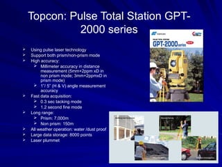
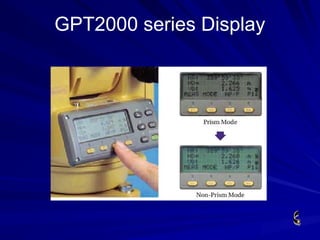
Topcon: Pulse TotalStation GPT-
2000 series
Using pulse laser technology
Support both prism/non-prism mode
High accuracy:
Millimeter accuracy in distance
measurement (5mm+2ppm xD in
non prism mode; 3mm+2ppmxD in
prism mode)
1”/ 5” (H & V) angle measurement
accuracy
Fast data acquisition:
0.3 sec tacking mode
1.2 second fine mode
Long range:
Prism: 7,000m
Non prism: 150m
All weather operation: water /dust proof
Large data storage: 8000 points
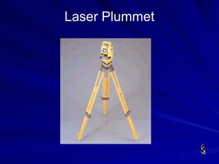
Laser plummet
39.
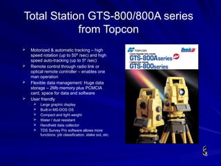
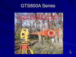
Total Station GTS-800/800Aseries
from Topcon
Motorized & automatic tracking – high
speed rotation (up to 50º /sec) and high
speed auto-tracking (up to 5º /sec)
Remote control through radio link or
optical remote controller – enables one
man operation
Flexible data management: Huge data
storage – 2Mb memory plus PCMCIA
card, space for data and software
User friendly
Large graphic display
Built-in MS-DOS OS
Compact and light weight
Water / dust resistant
Handheld data collector
TDS Survey Pro software allows more
functions: job classification, stake out, etc.
40.
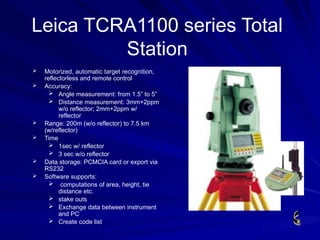
Motorized, automatictarget recognition,
reflectorless and remote control
Accuracy:
Angle measurement: from 1.5” to 5”
Distance measurement: 3mm+2ppm
w/o reflector; 2mm+2ppm w/
reflector
Range: 200m (w/o reflector) to 7.5 km
(w/reflector)
Time
1sec w/ reflector
3 sec w/o reflector
Data storage: PCMCIA card or export via
RS232
Software supports:
computations of area, height, tie
distance etc.
stake outs
Exchange data between instrument
and PC
Create code list
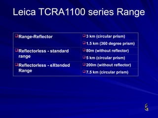
Leica TCRA1100 series Total
Station
41.
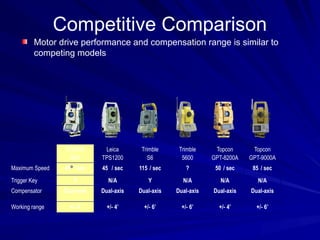
Competitive Comparison
Motor driveperformance and compensation range is similar to
competing models
SOKKIA
SRX
Leica
TPS1200
Trimble
S6
Trimble
5600
Topcon
GPT-8200A
Topcon
GPT-9000A
Maximum Speed 45º / sec 45º / sec 115º/ sec ? 50º/ sec 85º/ sec
Trigger Key Y N/A Y N/A N/A N/A
Compensator Dual-axis Dual-axis Dual-axis Dual-axis Dual-axis Dual-axis
Working range +/- 4’ +/- 4’ +/- 6’ +/- 6’ +/- 4’ +/- 6’
42.
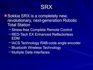
SRX
Sokkia SRX isa completely new,
revolutionary, next-generation Robotic
Total Station
– Stress-free Complete Remote Control
– RED-Tech EX Enhanced Reflectorless
EDM
– IACS Technology RAB-code angle encoder
– Bluetooth Wireless Technology
– Multiple Data Interfaces
43.
New Features
Completely newenvironmental-friendly design
New motors and jog dials for precise positioning and accurate aiming
Side mounted trigger key
New precise and reliable absolute encoders
New dual-mode Auto-pointing and Auto-tracking
New enhanced On-Demand Remote Control System
Integrated long-range Bluetooth wireless technology
New Enhanced EXtended reflectorless technology
New touch screen color display
Windows CE 5 operating system
New On-board software
Compact Flash Card support (up to 1GB) and USB ports
Serial data/power port.
Flexible power system
Dust proof and waterproof construction even when external devices are
connected
Total Stations
Prof. MohammedTaleb Obaidat
03/08/2025 46
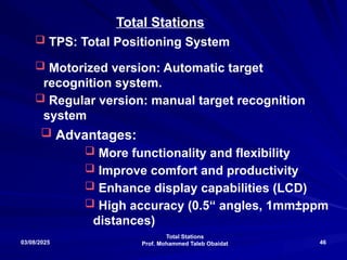
TPS: Total Positioning System
Motorized version: Automatic target
recognition system.
Regular version: manual target recognition
system
Total Stations
Advantages:
More functionality and flexibility
Improve comfort and productivity
Enhance display capabilities (LCD)
High accuracy (0.5“ angles, 1mm±ppm
distances)
47.
Total Stations
Prof. MohammedTaleb Obaidat
03/08/2025 47
Available Total Stations in
the Laboratory
TC 1200: Non-motorized (Manual)
TCM 1800: Motorized Leica Total Station
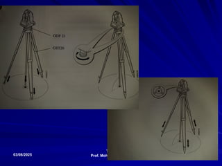
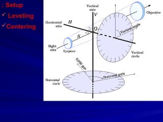
Setup:
Centering: Laser plummet
or optical one;
Leveling: legs and screws.
Leica TCRA1100 seriesRange
Range-Reflector 3 km (circular prism)
1.5 km (360 degree prism)
Reflectorless - standard
range
80m (without reflector)
5 km (circular prism)
Reflectorless - eXtended
Range
200m (without reflector)
7.5 km (circular prism)
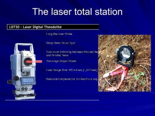
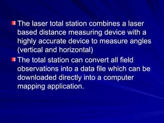
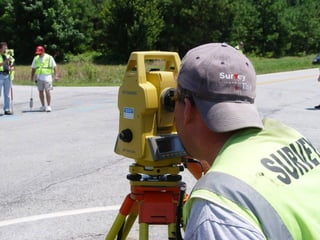
The laser totalstation combines a laser
based distance measuring device with a
highly accurate device to measure angles
(vertical and horizontal)
The total station can convert all field
observations into a data file which can be
downloaded directly into a computer
mapping application.
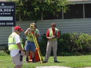
Application
Widely in use
Goodfor every type of scene
Accesses points that are hidden behind objects
Can be used at night and in moderately foul
weather conditions
Setup is about 5 minutes
Can be used while emergency crews are on
scene
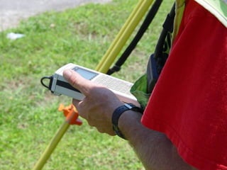
67.
Manpower Requirements
One operatorand one person for each
prism. At least one prism is necessary.
There are systems that can be operated
by one person.
Once the data is collected, it must be
uploaded onto a computer to process
68.
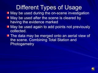
Different Types ofUsage
May be used during the on-scene investigation
May be used after the scene is cleared by
having the evidence marked
May be used again to add points not previously
collected.
The data may be merged onto an aerial view of
the scene. Combining Total Station and
Photogametry
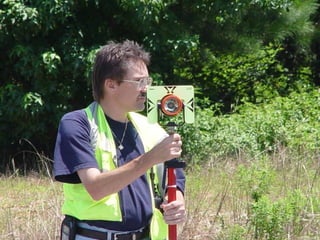
69.
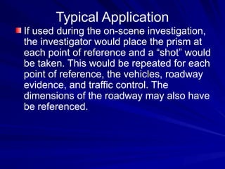
If used duringthe on-scene investigation,
the investigator would place the prism at
each point of reference and a “shot” would
be taken. This would be repeated for each
point of reference, the vehicles, roadway
evidence, and traffic control. The
dimensions of the roadway may also have
be referenced.
Typical Application
71.
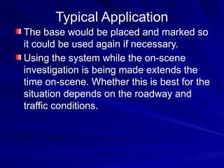
Typical Application
The basewould be placed and marked so
it could be used again if necessary.
Using the system while the on-scene
investigation is being made extends the
time on-scene. Whether this is best for the
situation depends on the roadway and
traffic conditions.
74.
Typical Application
If theevidence is marked, the scene can
be “shot” on a better date and time for the
traffic conditions. All the obstructions
would be gone and the traffic can be
controlled with better planning and
appropriate manpower.
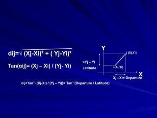
X
Y
i (Xi,Yi)
j (Xj,Yj)
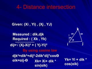
dij=√(Xj-Xi)² + ( Yj-Yi)²
Xj –Xi= Departure
Yj – Yi
=
Latitude
Tan(αij)= (Xj – Xi) / (Yj- Yi)
αij=Tanˉ¹((Xj-Xi) / (Yj – Yi))= Tanˉ¹(Departure / Latitude)
93.
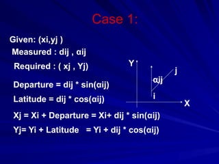
Case 1:
i
j
X
Y
αij
Given: (xi,yj)
Measured : dij , αij
Required : ( xj , Yj)
Departure = dij * sin(αij)
Latitude = dij * cos(αij)
Xj = Xi + Departure = Xi+ dij * sin(αij)
Yj= Yi + Latitude = Yi + dij * cos(αij)
94.
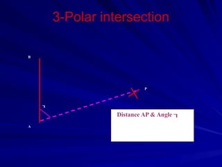
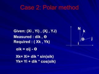
Case 2: Polarmethod
Ө
N
i
k
j
Given: (Xi , Yi) , (Xj , YJ)
Measured : dik , Ө
Required : ( Xk , Yk)
αik = αij - Ө
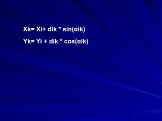
Xk= Xi+ dik * sin(αik)
Yk= Yi + dik * cos(αik)
95.
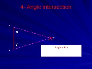
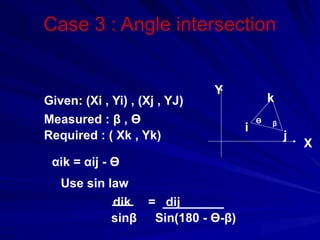
Case 3 :Angle intersection
β
Ө
i
j
k
X
Y
Given: (Xi , Yi) , (Xj , YJ)
Measured : β , Ө
Required : ( Xk , Yk)
αik = αij - Ө
Use sin law
dik = dij
sinβ Sin(180 - Ө-β)
Total Stations
Prof. MohammedTaleb Obaidat
03/08/2025 101
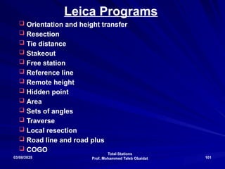
Leica Programs
Orientation and height transfer
Resection
Tie distance
Stakeout
Free station
Reference line
Remote height
Hidden point
Area
Sets of angles
Traverse
Local resection
Road line and road plus
COGO
102.
Total Stations
Prof. MohammedTaleb Obaidat
03/08/2025 102
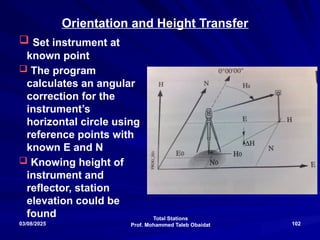
Orientation and Height Transfer
Set instrument at
known point
The program
calculates an angular
correction for the
instrument’s
horizontal circle using
reference points with
known E and N
Knowing height of
instrument and
reflector, station
elevation could be
found
103.
Total Stations
Prof. MohammedTaleb Obaidat
03/08/2025 103
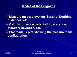
Modes of the Programs
Measure mode: elevation, Easting, Northing,
distances, etc.
Calculation mode: orientation, elevation,
standard deviation, etc.
Plot mode: a plot showing the measurement
configuration.
104.
Total Stations
Prof. MohammedTaleb Obaidat
03/08/2025 104
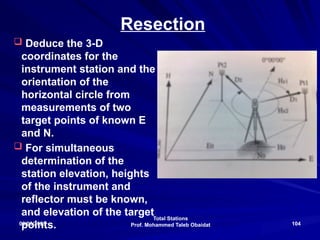
Resection
Deduce the 3-D
coordinates for the
instrument station and the
orientation of the
horizontal circle from
measurements of two
target points of known E
and N.
For simultaneous
determination of the
station elevation, heights
of the instrument and
reflector must be known,
and elevation of the target
points.
105.
Total Stations
Prof. MohammedTaleb Obaidat
03/08/2025 105
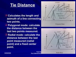
Tie Distance
Calculates the length and
azimuth of a line connecting
two points.
Polygonal mode: calculate
the distance between the
last two points measured.
Radial mode: calculate the
distance between the last
point measured (radial
point) and a fixed center
point.
106.
Total Stations
Prof. MohammedTaleb Obaidat
03/08/2025 106
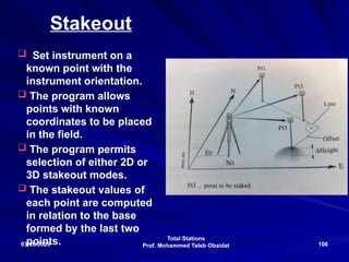
Stakeout
Set instrument on a
known point with the
instrument orientation.
The program allows
points with known
coordinates to be placed
in the field.
The program permits
selection of either 2D or
3D stakeout modes.
The stakeout values of
each point are computed
in relation to the base
formed by the last two
points.
107.
Total Stations
Prof. MohammedTaleb Obaidat
03/08/2025 107
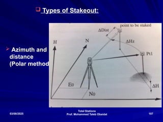
Types of Stakeout:
Azimuth and
distance
(Polar method)
108.
Total Stations
Prof. MohammedTaleb Obaidat
03/08/2025 108
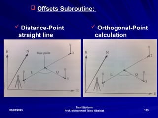
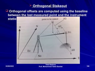
Orthogonal Stakeout
Orthogonal offsets are computed using the baseline
between the last measured point and the instrument
station
Total Stations
Prof. MohammedTaleb Obaidat
03/08/2025 110
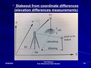
Stakeout from coordinate differences
(elevation differences measurements)
111.
Total Stations
Prof. MohammedTaleb Obaidat
03/08/2025 111
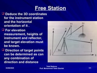
Free Station
Deduce the 3D coordinates
for the instrument station
and the horizontal
orientation of it .
For elevation
measurement, heights of
instrument and reflector,
and target elevation must
be known.
Direction of target points
can be determined as can
any combination of
direction and distance
112.
Total Stations
Prof. MohammedTaleb Obaidat
03/08/2025 112
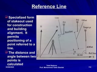
Reference Line
Specialized form
of stakeout used
for construction
and building
alignment. It
permits
positioning of a
point referred to a
line.
The distance and
angle between two
points is
calculated
113.
Total Stations
Prof. MohammedTaleb Obaidat
03/08/2025 113
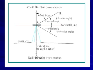
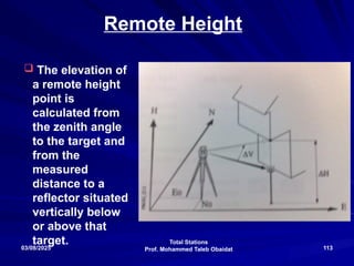
Remote Height
The elevation of
a remote height
point is
calculated from
the zenith angle
to the target and
from the
measured
distance to a
reflector situated
vertically below
or above that
target.
114.
Total Stations
Prof. MohammedTaleb Obaidat
03/08/2025 114
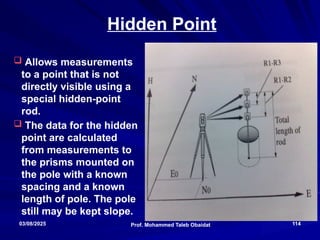
Hidden Point
Allows measurements
to a point that is not
directly visible using a
special hidden-point
rod.
The data for the hidden
point are calculated
from measurements to
the prisms mounted on
the pole with a known
spacing and a known
length of pole. The pole
still may be kept slope.
115.
Total Stations
Prof. MohammedTaleb Obaidat
03/08/2025 115
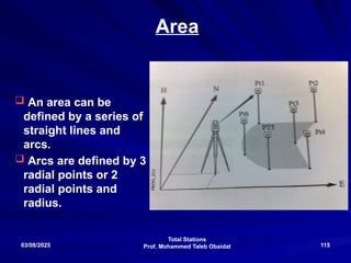
Area
An area can be
defined by a series of
straight lines and
arcs.
Arcs are defined by 3
radial points or 2
radial points and
radius.
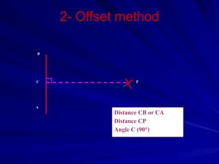
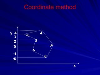
Coordinate method
x y
x1y1
x2 y2
x3 y3
x4 y4
x5 y5
x6 y6
x1 y1
n n
Area =1/2 [ Σ +ve –Σ –ve ]
i i
118.
Total Stations
Prof. MohammedTaleb Obaidat
03/08/2025 118
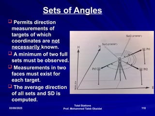
Sets of Angles
Permits direction
measurements of
targets of which
coordinates are not
necessarily known.
A minimum of two full
sets must be observed.
Measurements in two
faces must exist for
each target.
The average direction
of all sets and SD is
computed.
119.
Total Stations
Prof. MohammedTaleb Obaidat
03/08/2025 119
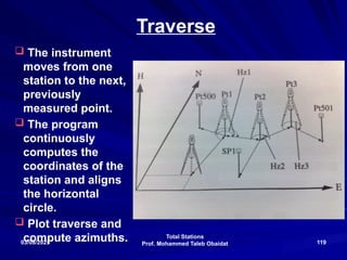
Traverse
The instrument
moves from one
station to the next,
previously
measured point.
The program
continuously
computes the
coordinates of the
station and aligns
the horizontal
circle.
Plot traverse and
compute azimuths.
120.
Total Stations
Prof. MohammedTaleb Obaidat
03/08/2025 120
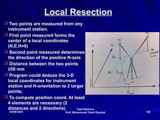
Local Resection
Two points are measured from any
instrument station.
First point measured forms the
center of a local coordinates
(N,E,H=0)
Second point measured determines
the direction of the positive N-axis
Distance between the two points
≥50 mm
Program could deduce the 3-D
local coordinates for instrument
station and H-orientation to 2 target
points.
To compute position coord. At least
4 elements are necessary (2
distances and 2 directions)
121.
Total Stations
Prof. MohammedTaleb Obaidat
03/08/2025 121
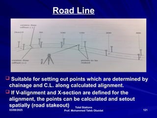
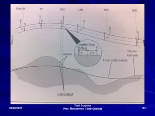
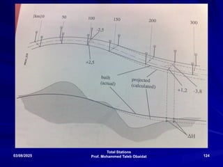
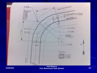
Road Line
Suitable for setting out points which are determined by
chainage and C.L. along calculated alignment.
If V-alignment and X-section are defined for the
alignment, the points can be calculated and setout
spatially (road stakeout)
122.
Total Stations
Prof. MohammedTaleb Obaidat
03/08/2025 122
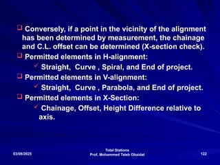
Conversely, if a point in the vicinity of the alignment
has been determined by measurement, the chainage
and C.L. offset can be determined (X-section check).
Permitted elements in H-alignment:
Straight, Curve , Spiral, and End of project.
Permitted elements in V-alignment:
Straight, Curve , Parabola, and End of project.
Permitted elements in X-Section:
Chainage, Offset, Height Difference relative to
axis.
Total Stations
Prof. MohammedTaleb Obaidat
03/08/2025 125
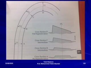
Road Plus
Allows for the stakeout of roads using the
typical offset method of construction staking.
In addition, the program supports station
equations, X-Section assignment by station, X-
Section definition, X-Section interpolation,
superelevation, widening, and slope
stake/catch points.
Total Stations
Prof. MohammedTaleb Obaidat
03/08/2025 128
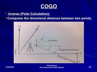
COGO
Inverse (Polar Calculation):
Computes the directional distance between two points.
129.
Total Stations
Prof. MohammedTaleb Obaidat
03/08/2025 129
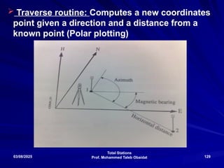
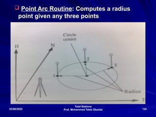
Traverse routine: Computes a new coordinates
point given a direction and a distance from a
known point (Polar plotting)
130.
Total Stations
Prof. MohammedTaleb Obaidat
03/08/2025 130
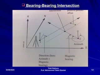
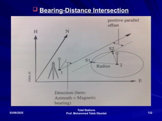
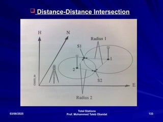
Intersections routine: Computes
Bearing-Bearing intersection.
Bearing-Distance intersection.
Distance-Distance intersection.
Total Stations
Prof. MohammedTaleb Obaidat
03/08/2025 137
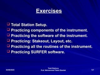
Exercises
Total Station Setup.
Practicing components of the instrument.
Practicing the software of the instrument.
Practicing: Stakeout, Layout, etc.
Practicing all the routines of the instrument.
Practicing SURFER software.
138.
Total Stations
Prof. MohammedTaleb Obaidat
03/08/2025 138
Projects
Project 1: Stakeout of a given coordinates
boundaries at JUST campus.
Project 2: Layout of a building and a road
at JUST campus.
Project 3: Use total station’s output
coordinates in SURFER SOFTWARE to plot
contours and make earth work
computations.
Project 4: Integrate total station’s output
with CAD and Land Development Software.
139.
Total Stations
Prof. MohammedTaleb Obaidat
03/08/2025 139
Prof. Mohammed Taleb Obaidat
Civil Engineering Department
Jordan University of Science and Technology (J.U.S.T.)
Irbid, JORDAN
E-Mail
:
mobaidat@just.edu.jo
Website: www.just.edu.jo/mobaidat


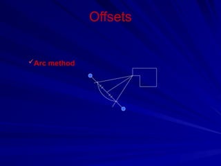
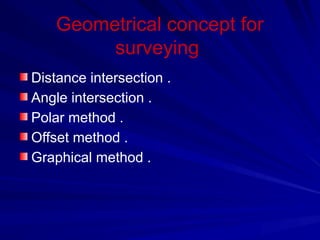
![Offsets [ perpendicular lines ]
3 - 4 - 5 [ phythagorion theorem ] .
Minimum distance .
Arc method .
Any instrument .](https://image.slidesharecdn.com/obaidat-total-station-250308090048-7165fc5b/85/PRESENTATION-ABOUT-TOTAL-STATION-PRICIPLES-AND-USAGE-79-320.jpg)
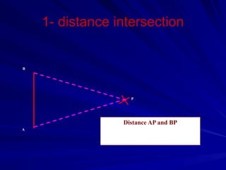
![Offsets
3 - 4 - 5 [ phythagorion theorem ] :-
C2
= a2
+ b2
Minimum distance :-
If d4>d3>d1>d2
d1 is
perpendicular
If Δ is low then the accuracy increased .
d1
d4
d3
d2
Δ](https://image.slidesharecdn.com/obaidat-total-station-250308090048-7165fc5b/85/PRESENTATION-ABOUT-TOTAL-STATION-PRICIPLES-AND-USAGE-80-320.jpg)
![Coordinate method
x y
x1 y1
x2 y2
x3 y3
x4 y4
x5 y5
x6 y6
x1 y1
n n
Area =1/2 [ Σ +ve –Σ –ve ]
i i](https://image.slidesharecdn.com/obaidat-total-station-250308090048-7165fc5b/85/PRESENTATION-ABOUT-TOTAL-STATION-PRICIPLES-AND-USAGE-117-320.jpg)