IRJET- Analog to Digital Conversion Process by Matlab Simulink
•
0 likes•9 views

https://www.irjet.net/archives/V5/i11/IRJET-V5I11263.pdf
![International Research Journal of Engineering and Technology (IRJET) e-ISSN: 2395-0056
Volume: 05 Issue: 11 | Nov 2018 www.irjet.net p-ISSN: 2395-0072
© 2018, IRJET | Impact Factor value: 7.211 | ISO 9001:2008 Certified Journal | Page 1367
2.5. OUTPUT DIGITAL SIGNAL
The output of the ADC has defined states and the number of
states is almost always two bits 0 and 1 which is called
binary.
3. SIMULINK MODEL & WAVEFORM
Figure 2: ADC Simulink Model
Figure 3: Analog Signal
Figure 3: Pulse Generator
Figure 4: Sampling
Figure 5: Quantizing.
Figure 6: Encoding
4. CONCLUSION
The Simulink ADC system has a sample-and-hold block
controlled by a sampling pulse generator, an 4 bit encoder
block.
REFERENCES
[1] L. W. Couch II, Modern Communication Systems:
Principle and Applications.
[2] K. Ogata, Modern Control Engineering. Upper Saddle
River, NJ, USA: Prentice Hall PTR, 4th ed., 2001.
[3] http://www.academia.edu/10301729/Abstract_An_Ana
log_to_Digital_converter_ADC_is_crucial
[4] https://www.elprocus.com/analog-to-digital-adc-
converter/
[5] https://whatis.techtarget.com/definition/analog-to-
digital-conversion-ADC
[6] https://ieeexplore.ieee.org/document/5407732/](data:image/gif;base64,R0lGODlhAQABAIAAAAAAAP///yH5BAEAAAAALAAAAAABAAEAAAIBRAA7)
Recommended
Recommended
More Related Content
What's hot
What's hot (20)
Similar to IRJET- Analog to Digital Conversion Process by Matlab Simulink
Similar to IRJET- Analog to Digital Conversion Process by Matlab Simulink (20)
More from IRJET Journal
More from IRJET Journal (20)
Recently uploaded
Recently uploaded (20)
IRJET- Analog to Digital Conversion Process by Matlab Simulink
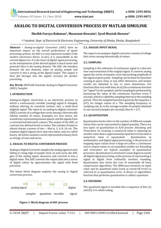
- 1. International Research Journal of Engineering and Technology (IRJET) e-ISSN: 2395-0056 Volume: 05 Issue: 11 | Nov 2018 www.irjet.net p-ISSN: 2395-0072 © 2018, IRJET | Impact Factor value: 7.211 | ISO 9001:2008 Certified Journal | Page 1366 ANALOG TO DIGITAL CONVERSION PROCESS BY MATLAB SIMULINK Sheikh Fareya Rahman1, Moazzam Hossain2, Syed Mostak Hossen3 1,2,3student, Dept. of Electrical & Electronic Engineering, University of Dhaka, Dhaka, Bangladesh ---------------------------------------------------------------------***--------------------------------------------------------------------- Abstract - Analog-to-digital Converters (ADC) have an important impact on the overall performance of signal processing systems. An ADC is a very important module in the modern electronics device. In fact, it is unavoidable in the current digital era. It is the heart of digital signal processing, as the manipulation of the desired signals is much easier and powerful than in the analog domain. The ADC, the interface between the two domains, takes an analog sample and converts it into a string of the digital output. This output is then fed through into the digital circuitry for further processing. Key Words: MATLAB Simulink, Analog to Digital Converter (ADC), Sampler. 1. INTRODUCTION Analog-to-digital conversion is an electronic process in which a continuously variable (analog) signal is changed, without altering its essential content, into a multi-level (digital) signal. The input to an analog-to-digital converter (ADC) consists of a voltage that varies among a theoretically infinite number of values. Examples are sine waves, the waveforms representinghumanspeech,andthesignalsfrom a conventional television camera. The output of the ADC, in contrast, has defined levels or states. The numberofstatesis almost always a power of two -- that is, 2, 4, 8, 16, etc. The simplest digital signals have only two states, and are called binary. All whole numberscanberepresentedin binary form as strings of ones and zeros. 2. ANALOG TO DIGITAL CONVERSION PROCESS Analog to Digital Convertersamplestheanalogsignaloneach falling or rising edge of sample clock. In each cycle, the ADC gets of the analog signal, measures and converts it into a digital value. The ADC converts the output data into a series of digital values by approximates the signal with fixed precision. The below block diagram explains the analog to digital conversion process. Figure 1: Block diagram of ADC process 2.1. ANALOG INPUT SIGNAL The input to an analog to digital converter consists ofvoltage that varies among theoretically of values. 2.2. SAMPLING Sampling is the reduction of continuous signal to a discrete time representation of the original signal .It converts analog signal into series of impulse, each representing amplitude of the signal at given point . Sampling can be done for functions varying in space, time, or any other dimension, and similar results are obtained in two or more dimensions. For functions that vary withtime,lets(t)beacontinuousfunction (or "signal") to be sampled, and letsamplingbeperformedby measuring the value of the continuous function every T seconds, which is calledthesamplingintervalorthesampling period. Then the sampled functionisgivenbythesequence:s (nT), for integer values of n. The sampling frequency or sampling rate, fs, is the average number of samples obtained in one second (samples per second), thus fs = 1/T. 2.3. QUANTIZATION Quantization levels refers to the number of different sample values that can be represented in digital quantity .There are two types of quantization in A/D process ;Rounting and Truncation .In rounting ,a numerical value is replacing by another value that is approximatelyequal butintruncationa numerical value is equaivalent . Quantization, in mathematics and digital signal processing, is the process of mapping input values from a large set (often a continuous set) to output values in a (countable) smaller set. Rounding and truncation are typical examples of quantization processes. Quantization is involved to some degreeinnearly all digital signal processing, as the process of representing a signal in digital form ordinarily involves rounding. Quantization also forms the core of essentially all lossy compression algorithms. The difference between an input value and its quantized value (such as round-off error) is referred to as quantization error. A device or algorithmic function that performs quantization is called a quantizer. 2.4. ENCODING The quantized signal is encoded into a sequence of bits (1) and (0), it is called coding.
- 2. International Research Journal of Engineering and Technology (IRJET) e-ISSN: 2395-0056 Volume: 05 Issue: 11 | Nov 2018 www.irjet.net p-ISSN: 2395-0072 © 2018, IRJET | Impact Factor value: 7.211 | ISO 9001:2008 Certified Journal | Page 1367 2.5. OUTPUT DIGITAL SIGNAL The output of the ADC has defined states and the number of states is almost always two bits 0 and 1 which is called binary. 3. SIMULINK MODEL & WAVEFORM Figure 2: ADC Simulink Model Figure 3: Analog Signal Figure 3: Pulse Generator Figure 4: Sampling Figure 5: Quantizing. Figure 6: Encoding 4. CONCLUSION The Simulink ADC system has a sample-and-hold block controlled by a sampling pulse generator, an 4 bit encoder block. REFERENCES [1] L. W. Couch II, Modern Communication Systems: Principle and Applications. [2] K. Ogata, Modern Control Engineering. Upper Saddle River, NJ, USA: Prentice Hall PTR, 4th ed., 2001. [3] http://www.academia.edu/10301729/Abstract_An_Ana log_to_Digital_converter_ADC_is_crucial [4] https://www.elprocus.com/analog-to-digital-adc- converter/ [5] https://whatis.techtarget.com/definition/analog-to- digital-conversion-ADC [6] https://ieeexplore.ieee.org/document/5407732/