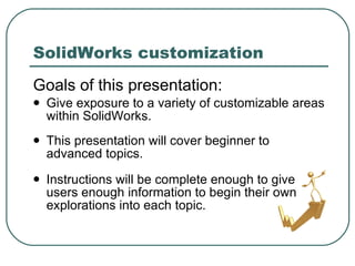
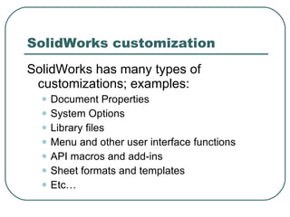
SolidWorks advanced customization techniques By Matthew Lorono March 23, 2010
SolidWorks customization Goals of this presentation: Give exposure to a variety of customizable areas within SolidWorks. This presentation will cover beginner to  advanced topics. Instructions will be complete enough to give users enough information to begin their own explorations into each topic.
SolidWorks customization SolidWorks has many types of customizations; examples: Document Properties System Options Library files Menu and other user interface functions API macros and add-ins Sheet formats and templates Etc…
This session will cover these topics: Tags Mouse Gestures Shortcut Bars Sheet Metal Gage Tables Hole Wizard holes (SHCS example) Hole Callout Format File Symbols SolidWorks customization
Backup Backup Backup! When editing installed files, always make a backup first! When making major edits to a file you create, always make a backup first so you can get back to the last working copy if something goes wrong with your edits.
Tags
Tags What are Tags? Tags are keywords that the user may add to SolidWorks documents or features to make them easier to filter and search. Functionality is available in SolidWorks 2008 and later.
Tags Applying tags to features In the view pane or FeatureManager design tree, select any feature. In the status bar (lower-right bottom of the SolidWorks window), click the Tags icon. Tags box will pop up near the icon and will include any tags already in use for that feature. Type new tags into that field, separating each with a semi-colon. (Click on the Tags icon again to close the Tags box.)
Tags Using tags with filter In the filter field (at the top of the FeatureManager design tree), type-in the desired tag.  This will automatically filter out all features which do not contain that tag nor match that text in their description. To redisplay all features, click cancel  x  in the filter field.
Mouse Gestures
Mouse Gestures What are Mouse Gestures? User-interface tool added in SolidWorks 2010. Donut shaped menu that pops in view pane when the user drags their mouse and RMB clicks at same time. Each direction of the mouse drag motion selects a different command.
Mouse Gestures Mouse Gestures menu may be customized by going to   Tools  pulldown>  Customize >  Mouse Gestures  tab Menu may have either 4 or 8 elements. Menu is mode sensitive
Mouse Gestures Tips: Common practice is to add Standard views to Mouse Gestures menu. Don’t add commands that end document sessions, such as  Exit  or  Close . Don’t add commands that trigger activities which cause long waits  Pack and Go .
Shortcut Bars
Shortcut Bars What are Shortcut Bars? Non-context pop-up menus that are customizable for four modes. Part Drawing Assembly Sketch Activated by pressing “S” key. Functionality added in SoildWorks 2008.
Customizing Shortcut Bars With nothing selected, press the “S” key. RMB click on the Shortcut Bar after it appears. Select  Customize . The  Customize  window will pop up. To add a command: drag a tool button from the  Button  area and drop onto the Shortcut Bar To remove a command, drag a tool button from the Shortcut Bar and drop it onto  Customize  window. Shortcut Bars
Shortcut Bars Tips: Add Extruded Boss and Extruded  Cut to Sketch Shortcut Bar to  reduce feature creation steps and  mouse movement. Don’t add commands that are already in the Context Toolbars (LMB click or RMB click menus)  Place the most commonly used commands towards the upper left of the Shortcut Bar. If you have device such as a high-end mouse or 3DConnexion SpacePilot), map the letter “S” to one of its buttons.  This reduces time consuming keyboard usage.
Sheet Metal Gauge Table
Sheet Metal Gauge Table What are Sheet Metal Gauge Tables? An excel spreadsheet where sheet metal gage properties are established for a particular material. Properties that may be assigned: Gage thickness Allowable bend radii K-factor
Sheet Metal Gauge Tables Sheet metal gage data is accessible while creating sheet metal features such as Base Flange and Edge Flange.
Sheet Metal Gauge Tables Establish location for gage table files: Place custom gage tables at install location, usually  C:\Program Files\<install folder>\lang\english\Sheet Metal Gauge Tables\ Or, point SolidWorks to another location at: Tools  pulldown> Options > System Options  tab> File Locations  selection> Sheet Metal Gauge Tables  drop down choice
Sheet Metal Gauge Table Network tip: Sheet Metal Gauge Tables can standardize material sizes through an enterprise. Multiple tables may be created for different material types (See SolidWorks Help to information about similar Sheet Metal Gauge/Bend Tables.)
Hole Wizard holes
Hole Wizard holes What is the Hole Wizard? Command that provides a user interface to create many types of hole features. Hole types created with Hole Wizard: Counterbore Countersink Hole Straight Tap Tapered Tap Legacy
Hole Wizard holes Standard Hole Wizard holes are linked to associated fastener hardware. Default hole dimensions are stored within Toolbox Setup with  associated hardware specifications.
Hole Wizard holes SolidWorks does not allow modification Toolbox “Standards” that come with the install. To modify hardware and hole defaults, custom Toolbox “Standard” must first be created.
Hole Wizard holes (SHCS) Potential issue with “standard” counter-bored holes for socket head cap screws :  Traditionally, counterbore depths for SHCS holes are equal to the diameter of the counterbore. SHCS often use the same depth for their head height too, thus nominally being line-to-line with the top surface of counterbore. Tolerances may allow the head to sit slightly proud of the top surface, possibly creating fit issues with other components.
Hole Wizard holes (SHCS) Demonstration task: Create customized “standard” for Socket Head Cap Screw (SHCS) counterbore holes with specific head clearance to resolve fit issue.
Hole Wizard holes (SHCS) Create a new Toolbox “standard” based on existing “standard” Open Toolbox Setup. Goto  Tools  pulldown> System Options  tab> Hole/Wizard/Toolbox  line> Configuration  button> On Tool Setup, select  1. Select your hardware . Select the standard you wish to copy and modify.
Hole Wizard holes (SHCS) Select the double-folder icon at the top of the icon view pane. Type in a name for the new “standard” and select the green checkmark. Note: depending on the size of the original “standard”, the copy process may take several minutes.
Hole Wizard holes (SHCS) Select the new “standard” and navigate the hardware types to reach Socket Head Cap Screw folder. In the  Standard Properties  area, select  Size .  A database of properties will display to the right side of the window. Horizontally scroll the properties view to the far right and enter .02 into each field in the  Head Clearance  column.
Hole Wizard holes (SHCS) Once all values are changed, select the save button and exit Toolbox Setup. Verification: open a part and create a new Hole Wizard hole feature that uses one of the SHCS counterbore holes in the new “standard”.  Validation: inspect the hole feature using Measure or the feature’s PropertyManager to make sure that new “standard” works as expected. (There are some bugs in older versions of SolidWorks.)
Hole Wizard holes (network use) Sharing Hole Wizard setting throughout an enterprise means sharing all of Toolbox as well. Sharing Toolbox can be simple for some, but complex for others.
Hole Wizard hole (network use) For a tiny to small sized single-site engineering group: Copy the  C:\SolidWorks Data  folder and all of it contents to a network location. Point all workstations to network location: Goto  Tools  pulldown> System Options  tab> Hole/Wizard/Toolbox  line> Browse  button> Find and select new location for  SolidWorks Data  folder.
Hole Callout Format File
Hole Callout Format File What is the Hole Callout Format File? For drawings, the file used by the Hole Callout command to create callouts for various types of holes. File name is  calloutformat.txt  and is usually in  C:\Program Files\<install folder>\lang\english\
Hole Callout Format File Potential issue with  calloutformat.txt :   SolidWorks’ tapped hole callout defaults to include drill size. Including a drill size within a tapped hole callout may be considered over-specification: Thread callout itself specifies the final form of the hole. Drill specification is process specific. It may actually be incorrect if a different process is used, such as roll forming or molding. (SolidWorks assumes drill process is used.)
Hole Callout Format File
Hole Callout Format File (tap) Demonstration task: Change  calloutformat.txt  so that drill size is not included in tapped hole callouts when using Hole Callout command. (scope limited to blind cosmetic thread hole feature for this demonstration)
Locate  calloutformat.tx t and make a backup copy. Then open  calloutformat.txt  with Windows Notepad or similar. Search for “[ANSI Inch]” and then the heading “TAPPED HOLES”. Hole Callout Format File (tap)
Hole Callout Format File (tap) Right below that heading will be this code: Replace those two lines with these two lines of code: Save  calloutformat.txt . TAP-BLIND=;\        <hw-threaddesc><hw-threadclass> <HOLE-DEPTH> <hw-threaddepth>  TAP-BLIND=<MOD-DIAM> <hw-tapdrldia> <HOLE-DEPTH> <hw-tapdrldepth>;\ <hw-threaddesc> <hw-threadclass> <HOLE-DEPTH> <hw-threaddepth> Copy text
Hole Callout Format File (tap) Verification: Re-read new lines of code.  Make sure that the spacing between tags is correct. (Those spaces sometimes toggle defaults within Hole Callout command.)  Exit Notepad. Validation: In SolidWorks, create a model with a blind tapped hole.  Create a drawing from that model and use Hole Callout on the tapped hole to ensure it displays correctly.
Hole Callout Format File (tap) Note: SolidWorks can remain open while editing  calloutformat.txt . Note: Existing hole callouts on drawings will not automatically change, even if a drawing is open while  calloutformat.txt  is updated.  Only new hole callouts will use the new default.  Old callouts will still need to be updated directly.
Symbols
Symbols What are Symbols? Symbols are special characters (such as degree, depth, diameter, etc.) that may be inserted into  dimensions or annotations by using their text ID (such as <MOD-DEG> for degree) or this button: Symbols are stored in a library file name  gtol.sym , which is located at:  c:\Program files\<install folder>\lang\english
Symbols Creating a new symbol Symbols must be simple geometric shapes formed with lines, arcs, circles, polylines and alphanumeric characters.
Symbols Symbols exist on an imaginary grid space where 0,0 is the lower left corner and 1,0 is the upper right corner. Symbols are not limited to this grid space.  Larger numbers than 1.0 are allowed, as are negative numbers  1.0 represents the height of a font as it is used in SolidWorks. 0,0 1,1
Symbols (eye) Demonstration task: Create a new symbol to represent visual inspection, such as an eye. (Note: Changes made to  Gtol.sym  while SolidWorks is open will not be available until SolidWorks is restarted)
Symbol (eye) Sketch new symbol on a grid. 0,0 1,1 } Height of font as displayed in SolidWorks
Symbol (eye) 0,0 1,1 Center 1,.5; Size .4 Center 1,.5; Size .60 Center 1,1; Size 1.4 Center 1,0; Size 1.4 30°
Symbol (eye) Create the following script based on  gtol.sym  instructions and the estimates from the sketch: #INSP,Inspection Symbols *EYE,Eye A,ARC 1,0,.7,30,150 A,ARC 1,1,.7,210,330 A,SARC 1,.5,.2,0,180 A,SARC 1,.5,.2,180,0 A,CIRCLE 1,.5,.3 Copy text
Symbol (eye) Close SolidWorks Create a backup of  gtol.sym . Open  gtol.sym  with Windows Notepad or similar text editor. At the end of  gtol.sym  file, add the new code. Verification: ensure the code is correct, then save  gtol.sym . Validation: Start SolidWorks and open a drawing.  Create annotation note and insert the new symbol.  Place other text along side to see where the symbol will line up.
Symbol (eye) If the symbol does not appear as desired, exit SolidWorks, re-evaluate your sketch, and make adjustments to your  gtol.sym  code.
Symbol (eye) Adjusted code: #INSP,Inspection Symbols *EYE,Eye A,ARC 1, .15 ,.7,30,150 A,ARC 1, .85 ,.7,210,330 A,SARC 1,.5,.2,0,180 A,SARC 1,.5,.2,180,0 A,CIRCLE 1,.5,.3 Copy text
Audience questions or comments?
Contact SolidWorks Legion http://fcsuper.com/swblog Follow me on Twitter http://twitter.com/fcsuper

SolidWorks Advanced Customization Techniques

  • 1.
    SolidWorks advanced customizationtechniques By Matthew Lorono March 23, 2010
  • 2.
    SolidWorks customization Goalsof this presentation: Give exposure to a variety of customizable areas within SolidWorks. This presentation will cover beginner to advanced topics. Instructions will be complete enough to give users enough information to begin their own explorations into each topic.
  • 3.
    SolidWorks customization SolidWorkshas many types of customizations; examples: Document Properties System Options Library files Menu and other user interface functions API macros and add-ins Sheet formats and templates Etc…
  • 4.
    This session willcover these topics: Tags Mouse Gestures Shortcut Bars Sheet Metal Gage Tables Hole Wizard holes (SHCS example) Hole Callout Format File Symbols SolidWorks customization
  • 5.
    Backup Backup Backup!When editing installed files, always make a backup first! When making major edits to a file you create, always make a backup first so you can get back to the last working copy if something goes wrong with your edits.
  • 6.
  • 7.
    Tags What areTags? Tags are keywords that the user may add to SolidWorks documents or features to make them easier to filter and search. Functionality is available in SolidWorks 2008 and later.
  • 8.
    Tags Applying tagsto features In the view pane or FeatureManager design tree, select any feature. In the status bar (lower-right bottom of the SolidWorks window), click the Tags icon. Tags box will pop up near the icon and will include any tags already in use for that feature. Type new tags into that field, separating each with a semi-colon. (Click on the Tags icon again to close the Tags box.)
  • 9.
    Tags Using tagswith filter In the filter field (at the top of the FeatureManager design tree), type-in the desired tag. This will automatically filter out all features which do not contain that tag nor match that text in their description. To redisplay all features, click cancel x in the filter field.
  • 10.
  • 11.
    Mouse Gestures Whatare Mouse Gestures? User-interface tool added in SolidWorks 2010. Donut shaped menu that pops in view pane when the user drags their mouse and RMB clicks at same time. Each direction of the mouse drag motion selects a different command.
  • 12.
    Mouse Gestures MouseGestures menu may be customized by going to Tools pulldown> Customize > Mouse Gestures tab Menu may have either 4 or 8 elements. Menu is mode sensitive
  • 13.
    Mouse Gestures Tips:Common practice is to add Standard views to Mouse Gestures menu. Don’t add commands that end document sessions, such as Exit or Close . Don’t add commands that trigger activities which cause long waits Pack and Go .
  • 14.
  • 15.
    Shortcut Bars Whatare Shortcut Bars? Non-context pop-up menus that are customizable for four modes. Part Drawing Assembly Sketch Activated by pressing “S” key. Functionality added in SoildWorks 2008.
  • 16.
    Customizing Shortcut BarsWith nothing selected, press the “S” key. RMB click on the Shortcut Bar after it appears. Select Customize . The Customize window will pop up. To add a command: drag a tool button from the Button area and drop onto the Shortcut Bar To remove a command, drag a tool button from the Shortcut Bar and drop it onto Customize window. Shortcut Bars
  • 17.
    Shortcut Bars Tips:Add Extruded Boss and Extruded Cut to Sketch Shortcut Bar to reduce feature creation steps and mouse movement. Don’t add commands that are already in the Context Toolbars (LMB click or RMB click menus) Place the most commonly used commands towards the upper left of the Shortcut Bar. If you have device such as a high-end mouse or 3DConnexion SpacePilot), map the letter “S” to one of its buttons. This reduces time consuming keyboard usage.
  • 18.
  • 19.
    Sheet Metal GaugeTable What are Sheet Metal Gauge Tables? An excel spreadsheet where sheet metal gage properties are established for a particular material. Properties that may be assigned: Gage thickness Allowable bend radii K-factor
  • 20.
    Sheet Metal GaugeTables Sheet metal gage data is accessible while creating sheet metal features such as Base Flange and Edge Flange.
  • 21.
    Sheet Metal GaugeTables Establish location for gage table files: Place custom gage tables at install location, usually C:\Program Files\<install folder>\lang\english\Sheet Metal Gauge Tables\ Or, point SolidWorks to another location at: Tools pulldown> Options > System Options tab> File Locations selection> Sheet Metal Gauge Tables drop down choice
  • 22.
    Sheet Metal GaugeTable Network tip: Sheet Metal Gauge Tables can standardize material sizes through an enterprise. Multiple tables may be created for different material types (See SolidWorks Help to information about similar Sheet Metal Gauge/Bend Tables.)
  • 23.
  • 24.
    Hole Wizard holesWhat is the Hole Wizard? Command that provides a user interface to create many types of hole features. Hole types created with Hole Wizard: Counterbore Countersink Hole Straight Tap Tapered Tap Legacy
  • 25.
    Hole Wizard holesStandard Hole Wizard holes are linked to associated fastener hardware. Default hole dimensions are stored within Toolbox Setup with associated hardware specifications.
  • 26.
    Hole Wizard holesSolidWorks does not allow modification Toolbox “Standards” that come with the install. To modify hardware and hole defaults, custom Toolbox “Standard” must first be created.
  • 27.
    Hole Wizard holes(SHCS) Potential issue with “standard” counter-bored holes for socket head cap screws : Traditionally, counterbore depths for SHCS holes are equal to the diameter of the counterbore. SHCS often use the same depth for their head height too, thus nominally being line-to-line with the top surface of counterbore. Tolerances may allow the head to sit slightly proud of the top surface, possibly creating fit issues with other components.
  • 28.
    Hole Wizard holes(SHCS) Demonstration task: Create customized “standard” for Socket Head Cap Screw (SHCS) counterbore holes with specific head clearance to resolve fit issue.
  • 29.
    Hole Wizard holes(SHCS) Create a new Toolbox “standard” based on existing “standard” Open Toolbox Setup. Goto Tools pulldown> System Options tab> Hole/Wizard/Toolbox line> Configuration button> On Tool Setup, select 1. Select your hardware . Select the standard you wish to copy and modify.
  • 30.
    Hole Wizard holes(SHCS) Select the double-folder icon at the top of the icon view pane. Type in a name for the new “standard” and select the green checkmark. Note: depending on the size of the original “standard”, the copy process may take several minutes.
  • 31.
    Hole Wizard holes(SHCS) Select the new “standard” and navigate the hardware types to reach Socket Head Cap Screw folder. In the Standard Properties area, select Size . A database of properties will display to the right side of the window. Horizontally scroll the properties view to the far right and enter .02 into each field in the Head Clearance column.
  • 32.
    Hole Wizard holes(SHCS) Once all values are changed, select the save button and exit Toolbox Setup. Verification: open a part and create a new Hole Wizard hole feature that uses one of the SHCS counterbore holes in the new “standard”. Validation: inspect the hole feature using Measure or the feature’s PropertyManager to make sure that new “standard” works as expected. (There are some bugs in older versions of SolidWorks.)
  • 33.
    Hole Wizard holes(network use) Sharing Hole Wizard setting throughout an enterprise means sharing all of Toolbox as well. Sharing Toolbox can be simple for some, but complex for others.
  • 34.
    Hole Wizard hole(network use) For a tiny to small sized single-site engineering group: Copy the C:\SolidWorks Data folder and all of it contents to a network location. Point all workstations to network location: Goto Tools pulldown> System Options tab> Hole/Wizard/Toolbox line> Browse button> Find and select new location for SolidWorks Data folder.
  • 35.
  • 36.
    Hole Callout FormatFile What is the Hole Callout Format File? For drawings, the file used by the Hole Callout command to create callouts for various types of holes. File name is calloutformat.txt and is usually in C:\Program Files\<install folder>\lang\english\
  • 37.
    Hole Callout FormatFile Potential issue with calloutformat.txt : SolidWorks’ tapped hole callout defaults to include drill size. Including a drill size within a tapped hole callout may be considered over-specification: Thread callout itself specifies the final form of the hole. Drill specification is process specific. It may actually be incorrect if a different process is used, such as roll forming or molding. (SolidWorks assumes drill process is used.)
  • 38.
  • 39.
    Hole Callout FormatFile (tap) Demonstration task: Change calloutformat.txt so that drill size is not included in tapped hole callouts when using Hole Callout command. (scope limited to blind cosmetic thread hole feature for this demonstration)
  • 40.
    Locate calloutformat.txt and make a backup copy. Then open calloutformat.txt with Windows Notepad or similar. Search for “[ANSI Inch]” and then the heading “TAPPED HOLES”. Hole Callout Format File (tap)
  • 41.
    Hole Callout FormatFile (tap) Right below that heading will be this code: Replace those two lines with these two lines of code: Save calloutformat.txt . TAP-BLIND=;\        <hw-threaddesc><hw-threadclass> <HOLE-DEPTH> <hw-threaddepth> TAP-BLIND=<MOD-DIAM> <hw-tapdrldia> <HOLE-DEPTH> <hw-tapdrldepth>;\ <hw-threaddesc> <hw-threadclass> <HOLE-DEPTH> <hw-threaddepth> Copy text
  • 42.
    Hole Callout FormatFile (tap) Verification: Re-read new lines of code. Make sure that the spacing between tags is correct. (Those spaces sometimes toggle defaults within Hole Callout command.) Exit Notepad. Validation: In SolidWorks, create a model with a blind tapped hole. Create a drawing from that model and use Hole Callout on the tapped hole to ensure it displays correctly.
  • 43.
    Hole Callout FormatFile (tap) Note: SolidWorks can remain open while editing calloutformat.txt . Note: Existing hole callouts on drawings will not automatically change, even if a drawing is open while calloutformat.txt is updated. Only new hole callouts will use the new default. Old callouts will still need to be updated directly.
  • 44.
  • 45.
    Symbols What areSymbols? Symbols are special characters (such as degree, depth, diameter, etc.) that may be inserted into dimensions or annotations by using their text ID (such as <MOD-DEG> for degree) or this button: Symbols are stored in a library file name gtol.sym , which is located at: c:\Program files\<install folder>\lang\english
  • 46.
    Symbols Creating anew symbol Symbols must be simple geometric shapes formed with lines, arcs, circles, polylines and alphanumeric characters.
  • 47.
    Symbols Symbols existon an imaginary grid space where 0,0 is the lower left corner and 1,0 is the upper right corner. Symbols are not limited to this grid space. Larger numbers than 1.0 are allowed, as are negative numbers 1.0 represents the height of a font as it is used in SolidWorks. 0,0 1,1
  • 48.
    Symbols (eye) Demonstrationtask: Create a new symbol to represent visual inspection, such as an eye. (Note: Changes made to Gtol.sym while SolidWorks is open will not be available until SolidWorks is restarted)
  • 49.
    Symbol (eye) Sketchnew symbol on a grid. 0,0 1,1 } Height of font as displayed in SolidWorks
  • 50.
    Symbol (eye) 0,01,1 Center 1,.5; Size .4 Center 1,.5; Size .60 Center 1,1; Size 1.4 Center 1,0; Size 1.4 30°
  • 51.
    Symbol (eye) Createthe following script based on gtol.sym instructions and the estimates from the sketch: #INSP,Inspection Symbols *EYE,Eye A,ARC 1,0,.7,30,150 A,ARC 1,1,.7,210,330 A,SARC 1,.5,.2,0,180 A,SARC 1,.5,.2,180,0 A,CIRCLE 1,.5,.3 Copy text
  • 52.
    Symbol (eye) CloseSolidWorks Create a backup of gtol.sym . Open gtol.sym with Windows Notepad or similar text editor. At the end of gtol.sym file, add the new code. Verification: ensure the code is correct, then save gtol.sym . Validation: Start SolidWorks and open a drawing. Create annotation note and insert the new symbol. Place other text along side to see where the symbol will line up.
  • 53.
    Symbol (eye) Ifthe symbol does not appear as desired, exit SolidWorks, re-evaluate your sketch, and make adjustments to your gtol.sym code.
  • 54.
    Symbol (eye) Adjustedcode: #INSP,Inspection Symbols *EYE,Eye A,ARC 1, .15 ,.7,30,150 A,ARC 1, .85 ,.7,210,330 A,SARC 1,.5,.2,0,180 A,SARC 1,.5,.2,180,0 A,CIRCLE 1,.5,.3 Copy text
  • 55.
  • 56.
    Contact SolidWorks Legionhttp://fcsuper.com/swblog Follow me on Twitter http://twitter.com/fcsuper