Downloaded 422 times


![Linkage Assembly SolidWorks 2011 Tutorial
Activity: Create the AXLE Part
Set the Menu bar toolbar and Menu bar menu.
9) Click SolidWorks to expand the Menu bar menu.
10) Pin the Menu bar as illustrated. Use both the Menu bar menu and the Menu bar toolbar
in this book.
The SolidWorks Help Topics contains step-by-step instructions for various
commands. The Help icon is displayed in the
dialog box or in the PropertyManager for each
feature.
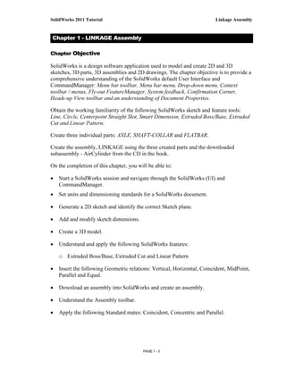
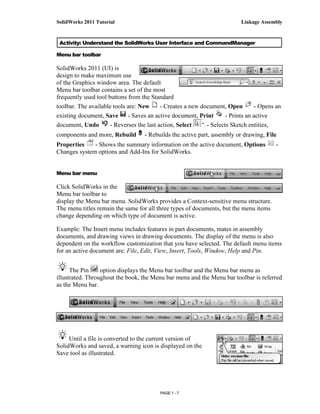
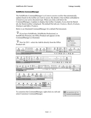
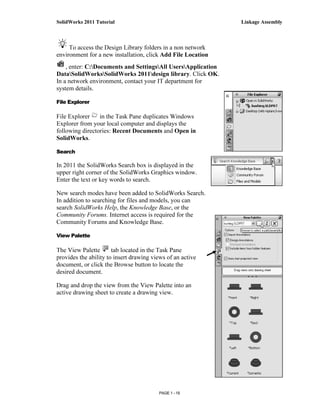
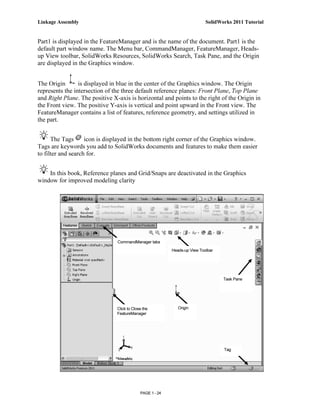
Set the Document Properties.
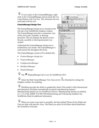
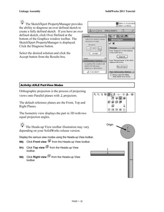
11) Click Options from the Menu bar. The System
Options General dialog box is displayed.
12) Click the Document
Properties tab.
13) Select ANSI from the
Overall drafting
standard drop-down
menu. Various Detailing
options are available
depending on the
selected standard.
Various detailing options are available
depending on the selected standard.
The Overall drafting standard determines the
display of dimension text, arrows, symbols, and
spacing. Units are the measurement of physical
Millimeters
quantities. Millimeter dimensioning and decimal
inch dimensioning are the two most common Inches
unit types specified for engineering parts and
drawings.
The primary units in this book are provided in
IPS, (inch, pound, second). The optional
secondary units are provided in MMGS,
(millimeters, grams, second) and are
indicated in brackets [ ].
PAGE 1 - 26](https://image.slidesharecdn.com/manualsolid2011-121119002025-phpapp02/85/Manual-solid-2011-28-320.jpg)
![SolidWorks 2011 Tutorial Linkage Assembly
Most illustrations are provided in both inches and millimeters.
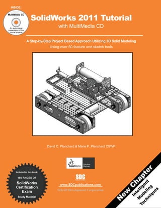
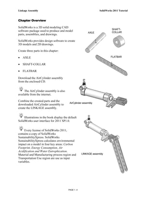
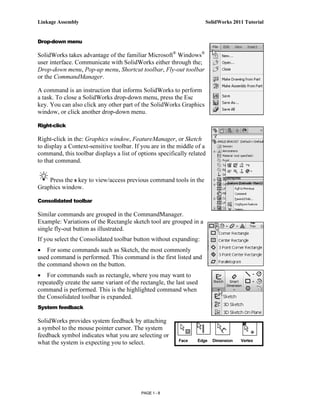
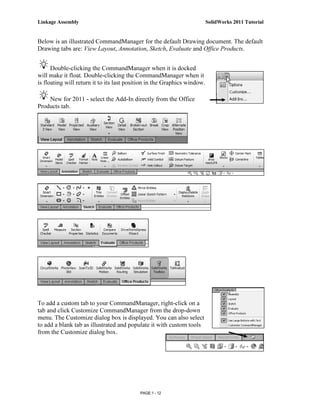
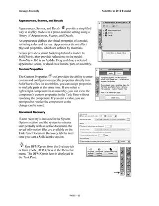
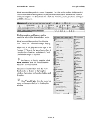
Set the document units.
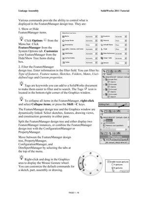
14) Click Units.
15) Click IPS (inch, pound, second)
[MMGS] for Unit system.
16) Select .123, [.12] (three decimal
places) for Length basic units.
17) Select None for Angle decimal
places.
18) Click OK from the Document
Properties - Units dialog box.
The Part FeatureManager is
displayed.
Activity: AXLE Part-Extruded Base Feature
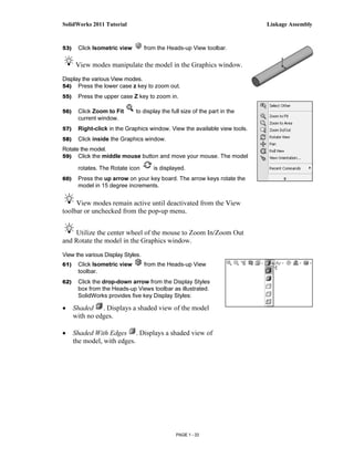
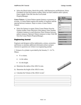
Insert a new sketch for the Extruded Base feature.
19) Right-click Front Plane from the FeatureManager. This is your Sketch plane. The Context
toolbar is displayed.
20) Click Sketch from the Context toolbar as illustrated.
Context
toolbar
Origin
PAGE 1 - 27](https://image.slidesharecdn.com/manualsolid2011-121119002025-phpapp02/85/Manual-solid-2011-29-320.jpg)
![SolidWorks 2011 Tutorial Linkage Assembly
25) Click a position to create the circle. The
activated circle is displayed in blue.
Add a dimension.
26) Click Smart Dimension from the Sketch
toolbar. The cursor displays the Smart
Dimension icon .
27) Click the circumference of the circle.
28) Click a position diagonally above the circle in
the Graphics window.
29) Enter .188in, [4.78] in the Modify dialog box.
30) Click the Green Check mark in the Modify
dialog box. The diameter of the
circle is .188 inches.
If required, click the blue arrow
head dots to toggle the direction of
the dimension arrow.
The circular sketch is centered at the Origin. The
dimension indicates the diameter of the circle.
To fit your sketch to the Graphics window,
press the f key.
Add relations, then dimensions. This will keep the
user from having too many unnecessary dimensions.
This helps to show the design intent of the model.
Dimension what geometry you intent to modify or
adjust.
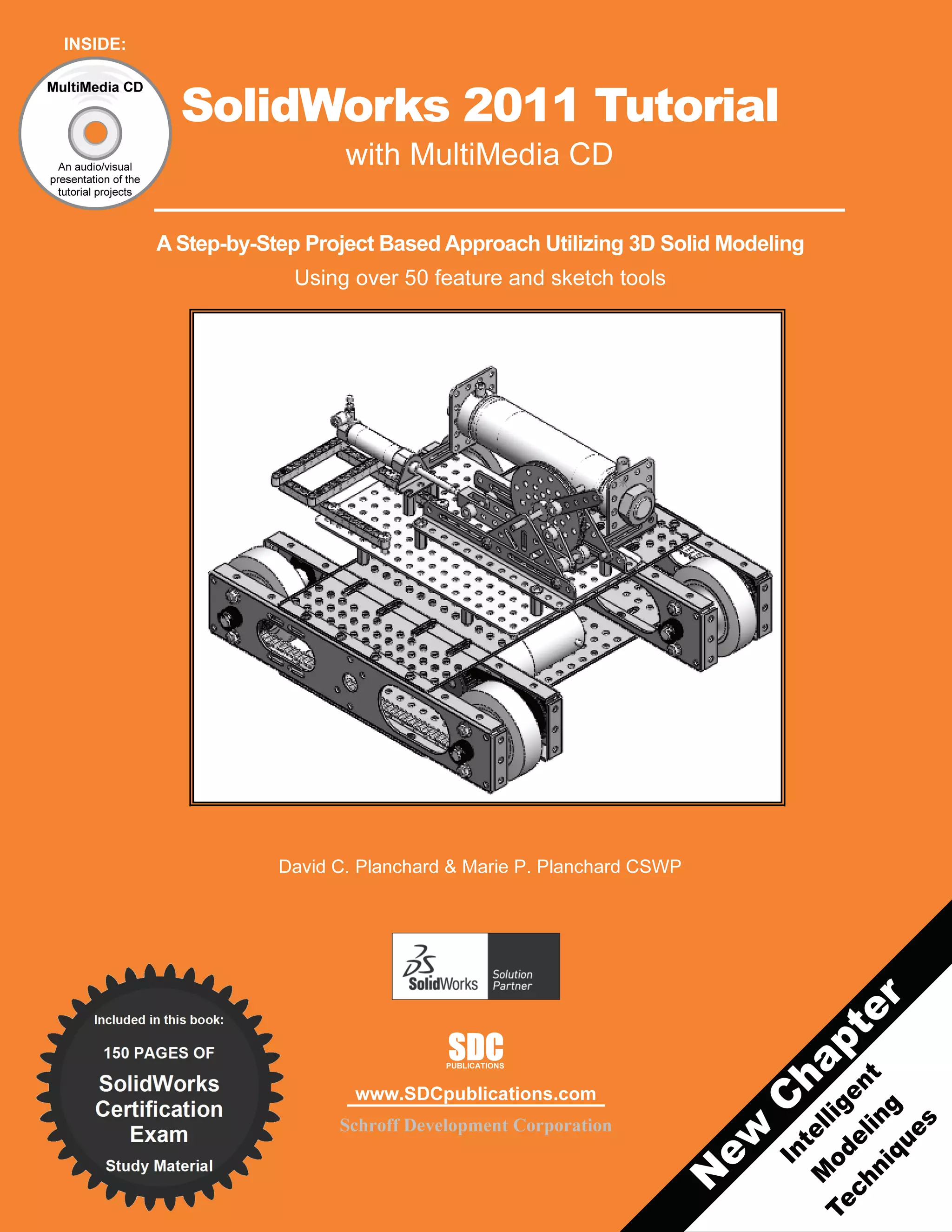
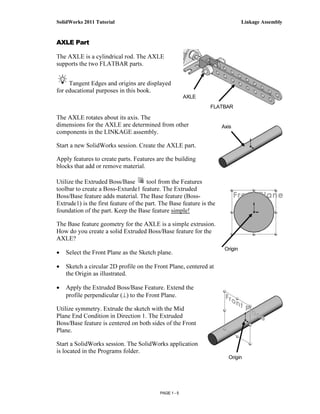
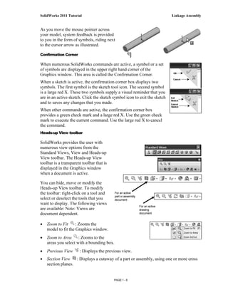
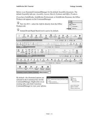
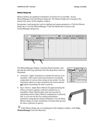
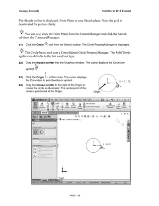
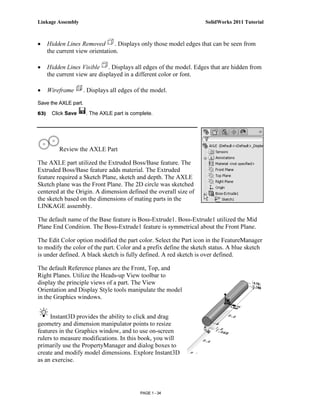
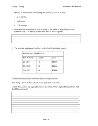
Extrude the sketch to create the Base Feature.
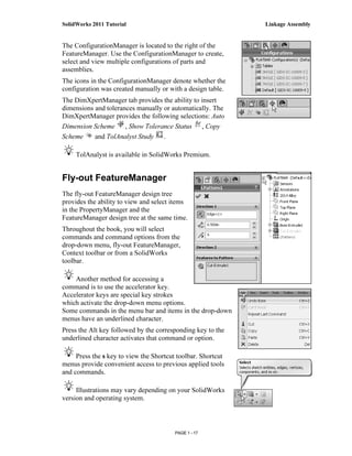
31) Click the Features tab from the CommandManager.
32) Click the Extruded Boss/Base Features tool. The
Boss-Extrude PropertyManager is displayed. Blind is
the default End Condition in Direction 1.
33) Select Mid Plane for End Condition in Direction 1.
34) Enter 1.375in, [34.93] for Depth in Direction 1. Accept
the default conditions.
35) Click OK from the Boss-Extrude PropertyManager.
Boss-Extrude1 is displayed in the FeatureManager.
PAGE 1 - 29](https://image.slidesharecdn.com/manualsolid2011-121119002025-phpapp02/85/Manual-solid-2011-31-320.jpg)
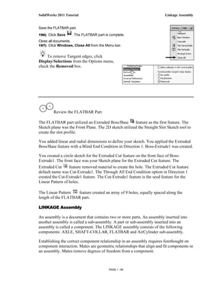
![Linkage Assembly SolidWorks 2011 Tutorial
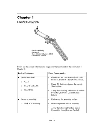
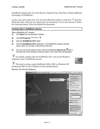
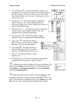
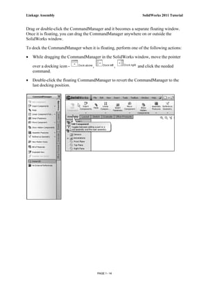
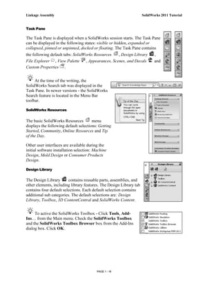
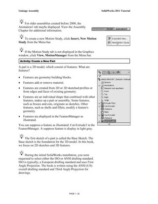
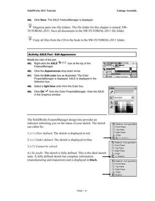
Fit the model to the Graphics window.
36) Press the f key. Note the
location of the Origin in the
model.
Use Symmetry. When possible
and if it makes sense, model objects
symmetrically about the origin.
Origin
The Boss-Extrude PropertyManager displays the parameters
utilized to define the feature. The Mid Plane End Condition in
the Direction 1 box extrudes the sketch equally on both sides of
the Sketch plane. The depth defines the extrude distance.
The Boss-Extrude1 feature name is displayed in the
FeatureManager. The FeatureManager lists the features, planes,
and other geometry that construct the part. Extrude features add
material. Extrude features require the following: Sketch Plane,
Sketch and depth.
The Sketch plane is the Front Plane. The Sketch is a circle with
the diameter of .188in, [4.76]. The Depth is 1.375in, [34.93].
Activity: AXLE Part-Save
Save the part.
37) Click Save As from the Drop-down Menu bar.
38) Double-click the MY-DOCUMENTS file folder. Note: The
procedure will be different depending on your Operating System.
39) Click the Create New Folder icon.
40) Enter SW-TUTORIAL-2011 for the file
folder name.
41) Double-click the SW-TUTORIAL-2011
file folder. SW-TUTORIAL-2011 is the
Save in file folder name.
42) Enter AXLE for the File name.
43) Enter AXLE ROD for the Description.
PAGE 1 - 30](https://image.slidesharecdn.com/manualsolid2011-121119002025-phpapp02/85/Manual-solid-2011-32-320.jpg)
![Linkage Assembly SolidWorks 2011 Tutorial
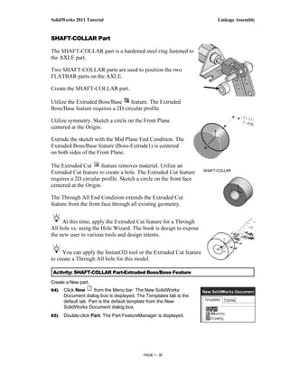
Save the part.
66) Click Save As from the drop-down Menu bar.
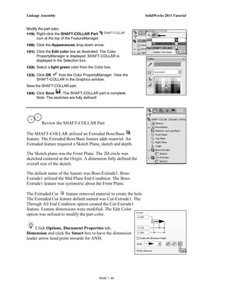
67) Enter SHAFT-COLLAR for File name in the
SW-TUTORIAL-2011 folder.
68) Enter SHAFT-COLLAR for
Description.
69) Click Save. The SHAFT-COLLAR
FeatureManager is displayed.
Set the Dimension standard and part units.
70) Click Options , Document
Properties tab from the Menu bar.
71) Select ANSI from the Overall
drafting standard drop-down menu.
72) Click Units.
73) Click IPS (inch, pound, second),
[MMGS] for Unit system.
74) Select .123, [.12] (three
decimal places) for
Length units Decimal
places.
75) Select None for
Angular units Decimal
places.
76) Click OK from the
Document Properties -
Units dialog box.
To view the Origin, click View,
Origins from the Menu bar menu.
When you create a new part or
assembly, the three default Planes
(Front, Right and Top) are align with
specific views. The Plane you select
for the Base sketch determines the
orientation of the part.
PAGE 1 - 36](https://image.slidesharecdn.com/manualsolid2011-121119002025-phpapp02/85/Manual-solid-2011-38-320.jpg)
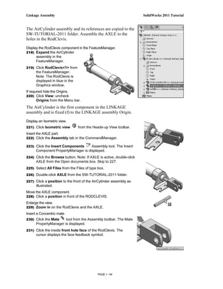
![SolidWorks 2011 Tutorial Linkage Assembly
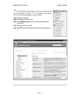
Insert a new sketch for the Extruded Base feature.
77) Right-click Front Plane from the FeatureManager. This is the
Sketch plane. The Context toolbar is displayed.
78) Click Sketch from the Context toolbar as illustrated. The
Sketch toolbar is displayed.
79) Click the Circle tool from the Sketch toolbar. The Circle
PropertyManager is displayed. The cursor displays the Circle
icon symbol .
80) Click the Origin . The cursor displays the Coincident to point
feedback symbol.
81) Drag the mouse pointer to the right of the Origin as illustrated.
82) Click a position to create the circle.
Add a dimension.
83) Click Smart Dimension from the Sketch toolbar.
84) Click the circumference of the circle. The cursor
displays the diameter feedback symbol.
85) Click a position diagonally above the circle in the
Graphics window.
86) Enter .4375in, [11.11] in the Modify dialog box.
87) Click the Green Check mark in the Modify dialog
box. The black sketch is fully defined.
Note: Three decimal places are displayed. The diameter
value .4375 rounds to .438.
Extrude the sketch to create the Base
feature.
88) Click the Features tab from the
CommandManager.
89) Click the Extruded Boss/Base
features tool. The Boss-
Extrude PropertyManager is
displayed.
90) Select Mid Plane for End
Condition in Direction 1.
91) Enter .250in, [6.35] for Depth.
Accept the default conditions.
Note the location of the Origin.
92) Click OK from the Boss-
Extrude PropertyManager. Boss-
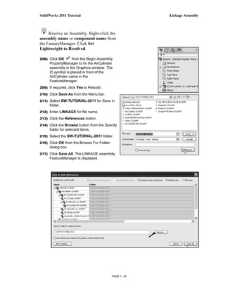
Extrude1 is displayed in the
FeatureManager.
PAGE 1 - 37](https://image.slidesharecdn.com/manualsolid2011-121119002025-phpapp02/85/Manual-solid-2011-39-320.jpg)
![Linkage Assembly SolidWorks 2011 Tutorial
Fit the model to the Graphics window.
93) Press the f key.
94) Click Isometric view from the Heads-Up View toolbar.
Save the model.
95) Click Save .
Activity: SHAFT-COLLAR Part-Extruded Cut Feature
Insert a new sketch for the Extruded Cut feature.
96) Right-click the front circular face of the Boss-Extrude1
feature for the Sketch plane. The mouse pointer displays the
face feedback icon.
View the mouse pointer feedback icon for the correct
geometry: line, face, point or vertex.
97) Click Sketch from the Context toolbar as
illustrated. The Sketch toolbar is displayed. This is your
Sketch plane!
98) Click Hidden Lines Removed from the Heads-up
View toolbar.
99) Click the Circle tool from the Sketch toolbar. The
Circle PropertyManager is displayed. The cursor
displays the Circle icon symbol .
100) Click the red Origin . The cursor displays the
Coincident to point feedback symbol.
101) Drag the mouse pointer to the right of the Origin.
102) Click a position to create the circle as illustrated.
Add a dimension.
103) Click the Smart Dimension Sketch tool.
Origin
104) Click the circumference of the circle.
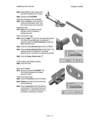
105) Click a position diagonally above the circle in the
Graphics window.
106) Enter .190in, [4.83] in the Modify dialog box.
107) Click the Green Check mark in the Modify dialog
box.
PAGE 1 - 38](https://image.slidesharecdn.com/manualsolid2011-121119002025-phpapp02/85/Manual-solid-2011-40-320.jpg)
![SolidWorks 2011 Tutorial Linkage Assembly
Insert an Extruded Cut feature.
108) Click the Features tab from the
CommandManager.
109) Click Extruded Cut from the Features
toolbar. The Cut-Extrude PropertyManager
is displayed.
110) Select Through All for End Condition in
Direction 1. The direction arrow points to the
right. Accept the default conditions.
111) Click OK from the Cut-Extrude PropertyManager. Cut-
Extrude1 is displayed in the FeatureManager.
The Extruded Cut feature is named Cut-Extrude1. The
Through All End Condition removes material from the Front
Plane through the Boss-Extrude1 geometry.
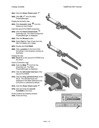
Model around the Origin: This is great for new user
because it provides them with a point of reference.
Activity: SHAFT-COLLAR-Modify Dimensions and Edit Color
Modify the dimensions.
112) Click Trimetric view from the Heads-up View toolbar.
113) Click the z key a few times to Zoom in.
114) Click the outside cylindrical face of the SHAFT-COLLAR.
The Boss-Extrude1 dimensions are displayed. Sketch
dimensions are displayed in black. The Extrude depth
dimensions are displayed in blue.
115) Click the .250in, [6.35] depth
dimension.
116) Enter .500in, [12.70].
The Boss-Extrude1 feature and Cut-
Extrude1 feature are modified.
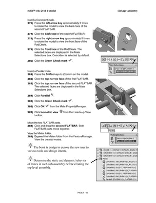
Return to the original dimensions.
117) Click the Undo tool from the Menu
bar.
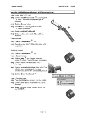
118) Click Shaded With Edges from the
Heads-up View toolbar.
PAGE 1 - 39](https://image.slidesharecdn.com/manualsolid2011-121119002025-phpapp02/85/Manual-solid-2011-41-320.jpg)
![Linkage Assembly SolidWorks 2011 Tutorial
136) Enter FLATBAR for File name in the
SW-TUTORIAL-2011 folder.
137) Enter FLAT BAR 9 HOLES for
Description.
138) Click Save. The FLATBAR
FeatureManager is displayed.
Set the Dimension standard and part units.
139) Click Options , Document
Properties tab from the Menu bar.
140) Select ANSI from the Overall drafting
standard drop-down menu.
141) Click Units.
142) Click IPS, [MMGS] for Unit
system.
143) Select .123, [.12] for Length
units Decimal places.
144) Select None for Angular units
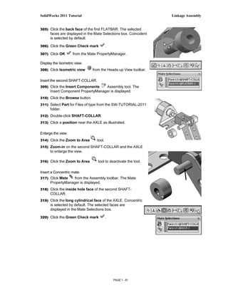
Decimal places.
145) Click OK to set the document
units.
Insert a new sketch for the Extruded
Base feature.
146) Right-click Front Plane from
the FeatureManager. This is
the Sketch plane.
147) Click Sketch from the
Context toolbar as illustrated.
The Sketch toolbar is
displayed.
Utilize the new Consolidated Slot Sketch
toolbar. Apply the Centerpoint
Straight Slot Sketch tool. The
Straight Slot Sketch tool provides
the ability to sketch a straight slot
from a centerpoint. In this
example, use the Origin as your
centerpoint.
148) Click the Centerpoint Straight
Slot tool from the Sketch
toolbar. The Slot
PropertyManager is displayed.
PAGE 1 - 44](https://image.slidesharecdn.com/manualsolid2011-121119002025-phpapp02/85/Manual-solid-2011-46-320.jpg)
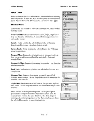
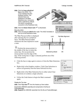
![SolidWorks 2011 Tutorial Linkage Assembly
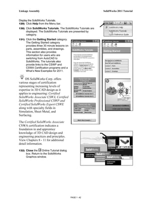
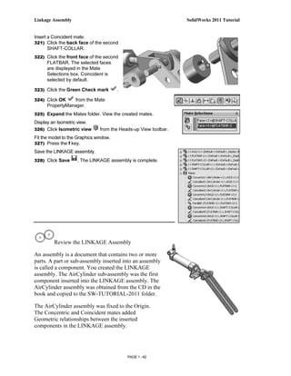
Create the Straight Slot with three points.
149) Click the Origin. This is your first point.
150) Click a point directly to the right of the
Origin. This is your second point.
151) Click a point directly above the second
point. This is your third point. The Straight
Slot is displayed. First Point Second Point
152) Click OK from the Slot PropertyManager.
View the Sketch relations.
153) Click View, Sketch Relations from the
Menu bar menu. View the sketch relations in
the Graphics window.
Deactivate the Sketch relations.
154) Click View; uncheck Sketch Relations from
the Menu bar. The Straight Slot Sketch tool
provides a midpoint relation with the Origin
and Equal relations between the other
sketch entities.
Add a dimension.
155) Click the Smart Dimension tool from the
Sketch toolbar.
156) Click the horizontal centerline.
157) Click a position above the top horizontal line in the Graphics
window.
158) Enter 4.000in, [101.6] in the Modify dialog box.
159) Click the Green Check mark in the Modify dialog box.
160) Click the right arc of the FLATBAR.
161) Click a position diagonally to the
right in the Graphics window.
162) Enter .250in, [6.35] in the Modify
dialog box.
163) Click the Green Check mark in
the Modify dialog box. The black
sketch is fully defined.
Model around the Origin: This is
great because it provides a point of
reference.
It’s considered best practice to fully define all sketches in the model. However; there
are times when this is not practical. Generally when using the spline tool to create a
freeform shape.
PAGE 1 - 45](https://image.slidesharecdn.com/manualsolid2011-121119002025-phpapp02/85/Manual-solid-2011-47-320.jpg)
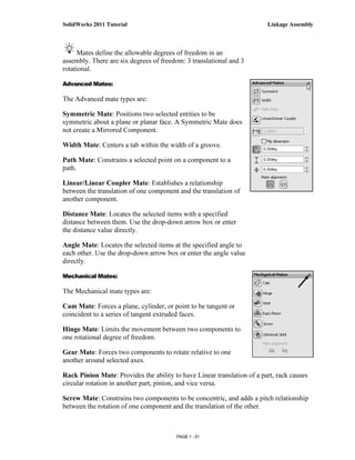
![Linkage Assembly SolidWorks 2011 Tutorial
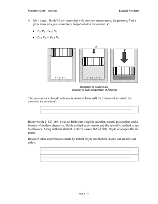
Extrude the sketch to create the Base (Boss-Extrude1) feature.
164) Click Extruded Boss/Base from the Features toolbar. The
Boss-Extrude PropertyManager is displayed.
165) Enter .090in, [2.29] for Depth. Accept the default conditions.
166) Click OK from the Boss-Extrude PropertyManager. Boss-
Extrude1 is displayed in the FeatureManager.
Fit the model to the Graphics window.
167) Press the f key.
Save the FLATBAR part.
168) Click Save .
Click View, Origins from
the Menu bar menu to display
the Origin in the Graphics
window.
Activity: FLATBAR Part-Extruded Cut Feature
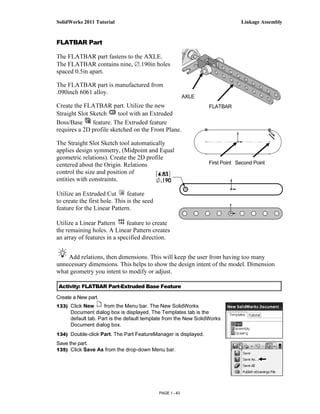
Insert a new sketch for the Extruded Cut Feature.
169) Right-click the front face of the Boss-Extrude1
feature in the Graphics window. This is the
Sketch plane. Boss-Extrude1 is highlighted in
the FeatureManager.
170) Click Sketch from the Context toolbar as
illustrated. The Sketch toolbar is displayed.
Display the Front view.
171) Click Front view from the Heads-up View
toolbar.
172) Click Hidden Lines Removed from the
Heads-up View toolbar.
The process of placing the mouse pointer over an
existing arc to locate its centerpoint is called
“wake up”.
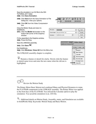
Rename a feature or sketch for clarity.
Slowly click the feature or sketch name twice
and enter the new name when the old one is
highlighted.
PAGE 1 - 46](https://image.slidesharecdn.com/manualsolid2011-121119002025-phpapp02/85/Manual-solid-2011-48-320.jpg)
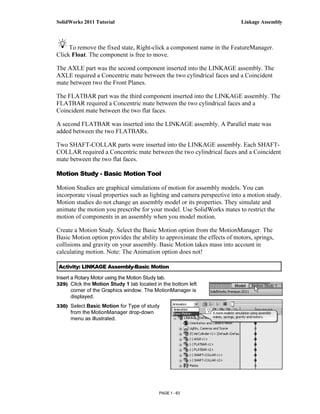
![SolidWorks 2011 Tutorial Linkage Assembly
Wake up the centerpoint. Centerpoint
173) Click the Circle Sketch tool from the Sketch toolbar. of the arc
The Circle PropertyManager is displayed.
174) Place the mouse pointer on the left arc. Do not click. The
centerpoint of the slot arc is displayed.
175) Click the centerpoint of the arc.
176) Click a position to the right of the centerpoint to create the circle
as illustrated.
Add a dimension.
177) Click the Smart Dimension Sketch tool.
178) Click the circumference of the circle.
179) Click a position diagonally above and to the left of
the circle in the Graphics window.
180) Enter .190in, [4.83] in the Modify box.
181) Click the Green Check mark in the Modify
dialog box.
182) Click Isometric view from the Heads-up View
toolbar.
183) Click Shaded With Edges from the Heads-up
View toolbar.
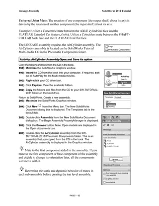
Insert an Extruded Cut feature.
184) Click the Features tab from the CommandManager.
185) Click Extruded Cut from the Features toolbar.
The Cut- Extrude PropertyManager is displayed.
186) Select Through All for End Condition in Direction 1.
The direction arrow points to the back. Accept the
default conditions.
187) Click OK from the Cut-Extrude
PropertyManager. The Cut-Extrude1 feature is
displayed in the FeatureManager.
Save the FLATBAR part.
188) Click Save .
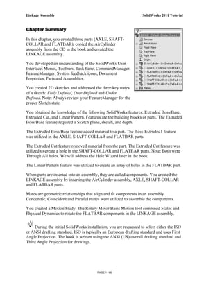
Think design intent. When do you use various
End Conditions? What are you trying to do with the
design? How does the component fit into an Assembly?
PAGE 1 - 47](https://image.slidesharecdn.com/manualsolid2011-121119002025-phpapp02/85/Manual-solid-2011-49-320.jpg)
![Linkage Assembly SolidWorks 2011 Tutorial
The blue Cut-Extrude1 icon indicates that the feature is selected.
Select features by clicking their icons in the FeatureManager or by
selecting their geometry in the Graphics window.
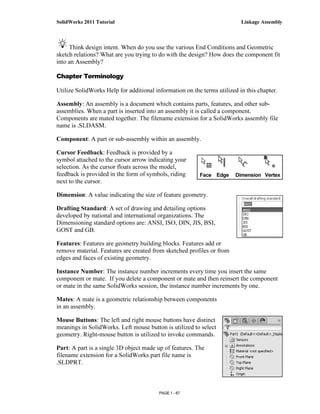
When you create a new part or assembly, the three default
Planes (Front, Right and Top) are align with specific views. The
Plane you select for the Base sketch determines the orientation of
the part.
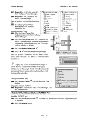
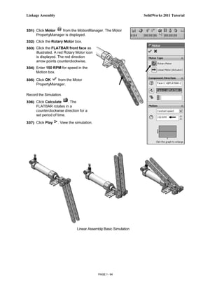
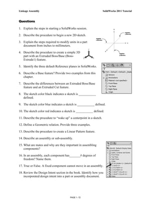
Activity: FLATBAR Part-Linear Pattern Feature
Create a Linear Pattern feature.
189) Click the Linear Pattern tool from the
Features toolbar. The Linear Pattern
PropertyManager is displayed. Cut-Extrude1 is
displayed in the Features to Pattern box. Note: If
Cut-Extrude1 is not displayed, click inside the
Features to Pattern box. Click Cut-Extrude1 from
the fly-out FeatureManager.
190) Click the top edge of the Boss-Extrude1 feature
for Direction1 in the Graphics window. Edge<1>
is displayed in the Pattern Direction box.
191) Enter 0.5in, [12.70] for Spacing.
192) Enter 9 for Number of Instances. Instances
are the number of occurrences of a feature.
193) The Direction arrow points to the right. Click
the Reverse Direction button if
required.
194) Check Geometry Pattern from the Options
box.
195) Click OK from the Linear Pattern
PropertyManager. The LPattern1 feature is
displayed in the FeatureManager.
PAGE 1 - 48](https://image.slidesharecdn.com/manualsolid2011-121119002025-phpapp02/85/Manual-solid-2011-50-320.jpg)
![Linkage Assembly SolidWorks 2011 Tutorial
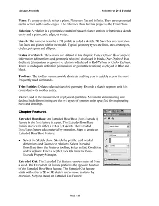
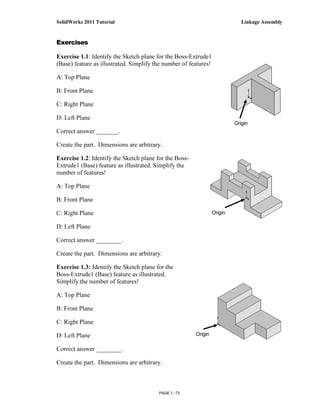
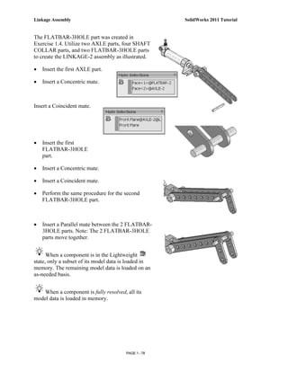
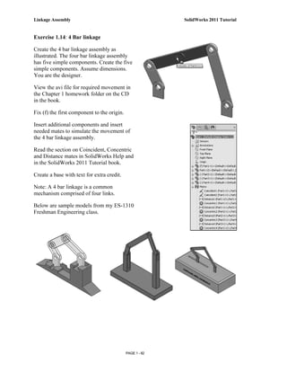
Exercise 1.4: FLATBAR - 3HOLE Part
Create an ANSI, IPS FLATBAR - 3HOLE part document.
• Utilize the Front Plane for the Sketch plane. Insert an
Extruded Base (Boss-Extrude1) feature. No Tangent Edges
displayed.
• Create an Extruded Cut feature. This is your seed feature.
Apply the Linear Pattern feature. The FLATBAR - 3HOLE
part is manufactured from 0.06in., [1.5mm] 6061 Alloy.
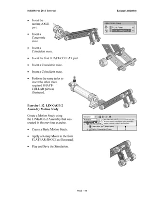
Exercise 1.5: FLATBAR - 5HOLE Part
Create an ANSI, IPS, FLATBAR - 5HOLE part as illustrated.
• Utilize the Front Plane for the Sketch plane. Insert an
Extruded Base (Boss-Extrude1) feature.
• Create an Extruded Cut feature. This is your seed feature.
Apply the Linear Pattern feature. The FLATBAR - 5HOLE
part is manufactured from 0.06in, [1.5mm] 6061 Alloy.
• Calculate the required dimensions for the FLATBAR -
5HOLE part. Use the following information: Holes are
.500in. on center, Radius is .250in., and Hole diameter is
.190in.
• No Tangent
Edges displayed.
Think design
intent. When do you
use the various End
Conditions and Geometric sketch relations? What are you
trying to do with the design? How does the component fit into
an Assembly?
PAGE 1 - 74](https://image.slidesharecdn.com/manualsolid2011-121119002025-phpapp02/85/Manual-solid-2011-76-320.jpg)

The document provides an overview of Chapter 1 which will cover creating individual parts and assembling them into a LINKAGE assembly using SolidWorks. Students will learn the SolidWorks user interface and how to create sketches, extruded features, and apply patterns. The chapter will also cover creating an assembly and applying mates. Three parts will be made - an AXLE, SHAFT-COLLAR, and FLATBAR which will be combined with a downloaded AIRCYLINDER assembly into the final LINKAGE assembly.