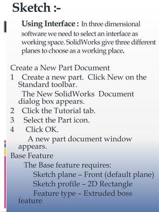
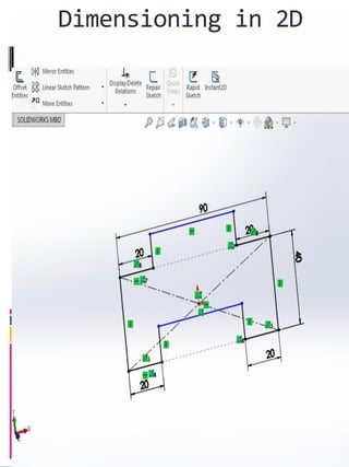
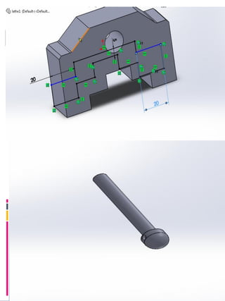
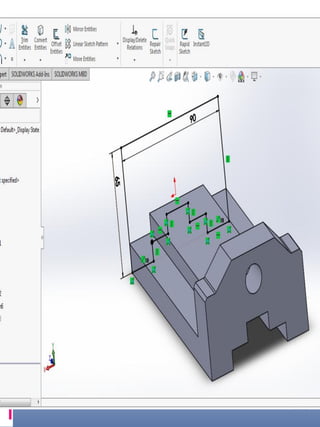
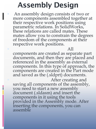
SolidWorks is a 3D CAD software used by over 2 million engineers. It was founded in 1993 by Jon Hirschtick and was later acquired by Dassault Systèmes. SolidWorks allows users to design parts and assemble them in 3D. Key aspects covered include sketching, extruding 2D profiles to create 3D features, dimensioning sketches and parts, creating assemblies using mates, and generating detailed drawings with multiple views dimensioned according to ISO standards.
NX is one of the world’s most advanced and tightly integrated CAD/CAM/CAE product development solutions. Spanning the entire range of product development, NX delivers immense value to enterprises of all sizes. It simplifies complex product designs, thus speeding up the process of introducing products to the market.
Radial Engine is a reciprocating type Internal Combustion engine in which the cylinders point outwards from a central crankshaft like the spokes on a wheel. This type of engine was commonly used in most of the aircrafts before they started using turbine engines.
CAD is one part of the whole Digital Product Development (DPD) activity within the Product Lifecycle Management (PLM) processes, and as such is used together with other tools, which are either integrated modules or stand-alone products, such as:
• Computer-aided engineering (CAE) and Finite element analysis (FEA)
• Computer-aided manufacturing (CAM) including instructions to Computer Numerical Control (CNC) machines
• Photo realistic rendering and Motion Simulation.
• Document management and revision control using Product Data Management (PDM).
Commonly referred to as a 3D Product Lifecycle Management software suite, CATIA supports multiple stages of product development (CAx), including conceptualization, design (CAD), engineering (CAE) and manufacturing (CAM). CATIA facilitates collaborative engineering across disciplines around its 3D EXPERIENCE platform, including surfacing & shape design, electrical, fluid and electronic systems design, mechanical engineering and systems engineering.
DESIGN FOR MANUFACTURING AND ASSEMBLY.A really good insight of DFA and DFM. Also includes a very precise and appealing caste study on aimplemention of DFMA on a motor drive assembly.
What is process planning .Difficulties in traditional process planning,CAPP Model,Types of CAPP ,1.Retrieval type CAPP (variant) systems.
2.Generative CAPP systems.
3.Hybrid CAPP systems.
Process planning system , Machinability data systems , Benefits of CAPP
This document is an Instruction manual for Computer aided machine drawing
Subject: Computer aided machine drawing (CAMD)
Syllabus contest is as per VTU, Belagavi, India.
Notes Compiled By: Hareesha N Gowda, Assistant Professor, DSCE, Bengaluru-78.
This course material is designed for Engineers and other interested personals who want to work specially mechanical drawings using AutoCad software. it is prepared just like a manual or guide line that can help the individuals learn autocad without any assistance. so enjoy it and if you have any question you can ask in my email: jerryhenok2016@gmail.com
Hello everyone! I am thrilled to present my latest portfolio on LinkedIn, marking the culmination of my architectural journey thus far. Over the span of five years, I've been fortunate to acquire a wealth of knowledge under the guidance of esteemed professors and industry mentors. From rigorous academic pursuits to practical engagements, each experience has contributed to my growth and refinement as an architecture student. This portfolio not only showcases my projects but also underscores my attention to detail and to innovative architecture as a profession.
Dive into the innovative world of smart garages with our insightful presentation, "Exploring the Future of Smart Garages." This comprehensive guide covers the latest advancements in garage technology, including automated systems, smart security features, energy efficiency solutions, and seamless integration with smart home ecosystems. Learn how these technologies are transforming traditional garages into high-tech, efficient spaces that enhance convenience, safety, and sustainability.
Ideal for homeowners, tech enthusiasts, and industry professionals, this presentation provides valuable insights into the trends, benefits, and future developments in smart garage technology. Stay ahead of the curve with our expert analysis and practical tips on implementing smart garage solutions.
You could be a professional graphic designer and still make mistakes. There is always the possibility of human error. On the other hand if you’re not a designer, the chances of making some common graphic design mistakes are even higher. Because you don’t know what you don’t know. That’s where this blog comes in. To make your job easier and help you create better designs, we have put together a list of common graphic design mistakes that you need to avoid.
Can AI do good? at 'offtheCanvas' India HCI preludeAlan Dix
Invited talk at 'offtheCanvas' IndiaHCI prelude, 29th June 2024.
https://www.alandix.com/academic/talks/offtheCanvas-IndiaHCI2024/
The world is being changed fundamentally by AI and we are constantly faced with newspaper headlines about its harmful effects. However, there is also the potential to both ameliorate theses harms and use the new abilities of AI to transform society for the good. Can you make the difference?
Book Formatting: Quality Control Checks for DesignersConfidence Ago
This presentation was made to help designers who work in publishing houses or format books for printing ensure quality.
Quality control is vital to every industry. This is why every department in a company need create a method they use in ensuring quality. This, perhaps, will not only improve the quality of products and bring errors to the barest minimum, but take it to a near perfect finish.
It is beyond a moot point that a good book will somewhat be judged by its cover, but the content of the book remains king. No matter how beautiful the cover, if the quality of writing or presentation is off, that will be a reason for readers not to come back to the book or recommend it.
So, this presentation points designers to some important things that may be missed by an editor that they could eventually discover and call the attention of the editor.
3. Introduction
The Solid Works software is a solid modeling
computer aided design (CAD) and computer
aided engineering (CAE) software program
that runs on Microsoft Windows. The
SolidWorks is produced by the Dassault
Systems— a subsidiary of Dassault Systèmes.
Solid Works is currently used by over 2 million
engineers and designers at more than 165,000 .
SOLIDWORKS Corporation was
founded in December 1993 by Massachusetts
Institute of Technology graduate Jon
Hirschtick; Hirschtick used $1 million he had
made while a member of the MIT Blackjack
Team to set up the company. Initially based in
Waltham, Massachusetts, USA, Hirschtick
recruited a team of engineers with the goal of
building 3D CAD software that was easy-to-
use, affordable, and available on the Windows
desktop. Operating later from Concord,
Massachusetts, SOLIDWORKS released its first
product SolidWorks 95, in 1995.[5][6] In 1997
Dassault, best known for its CATIA CAD
software, acquired SolidWorks for $310 million
in stock.
4. Introduction
• SolidWorks, 3D PartStream.NET, 3D Content
Central,
eDrawings, and the eDrawings logo are
registered trademarks
and FeatureManager is a jointly owned registered
trademark of
DS SolidWorks.
Circuit Works, Feature Palette, FloXpress,
PhotoWorks,
TolAnalyst, and XchangeWorks are trademarks of
DS
SolidWorks.
Feature Works is a registered trademark of
Geometric Software
Solutions Ltd.
SolidWorks 2011, SolidWorks Enterprise PDM,
SolidWorks
Simulation, SolidWorks Flow Simulation, and
eDrawings
Professional are product names of DS
SolidWorks.
5. Contents
Part Design
2D design (Sketch) , 3D
design (Features) , Part
design consider in the
part design section
Assembly Design
Assembling of two or
more than two parts
consider in this section
Drawing
Designing with
standards is consider
in the drawing section
6. Sketch :-
Using Interface : In three dimensional
software we need to select an interface as
working space. SolidWorks give three different
planes to choose as a working place.
Create a New Part Document
1 Create a new part. Click New on the
Standard toolbar.
The New SolidWorks Document
dialog box appears.
2 Click the Tutorial tab.
3 Select the Part icon.
4 Click OK.
A new part document window
appears.
Base Feature
The Base feature requires:
Sketch plane – Front (default plane)
Sketch profile – 2D Rectangle
Feature type – Extruded boss
feature
7. Open a Sketch
1 Click to select the Front plane in the Feature
Manager design tree.
2 Open a 2D sketch. Click Sketch on the Sketch
toolbar.
8. Confirmation Corner
When many SolidWorks commands are
active, a symbol or a set of symbols
appears in the
upper right corner of the graphics area. This
area is called the Confirmation Corner.
Sketch Indicator
When a sketch is active, or open, a
symbol appears in the confirmation corner
that looks like the Sketch tool. It provides a
visual reminder that you are active in a
sketch.
Clicking this symbol exits the sketch
saving your changes.
Clicking the red X exits the sketch
discarding your changes.
9. When other commands are
active, the confirmation
corner displays two
symbols: a check mark and an
X. The check mark executes the
current
command. The X cancels the
command.
17. Assembly Design
An assembly design consists of two or
more components assembled together at
their respective work positions using
parametric relations. In SolidWorks,
these relations are called mates. These
mates allow you to constrain the degrees
of freedom of the components at their
respective work positions.
All
components are created as separate part
documents, and then they are placed and
referenced in the assembly as external
components. In this type of approach, the
components are created in the Part mode
and saved as the (.sldprt) documents.
After creating and
saving all components of the assembly,
you need to start a new assembly
document (.sldasm) and insert the
components in it using the tools
provided in the Assembly mode. After
inserting the components, you can
assemble
18. Assembly mates :
After designing the parts ,
now they are assembled by using the
mate technology. While doing assembly
the mates are the main point to be
remember. In Solid Works, mates can
be applied using the Mate Property
Manager. Choose the Mate button in
the Assemble Command Manager or
choose Insert > Mate from the. Select a
planar face, curved face, axis, or a point
on the first component and then select
the entity from the second component;
the selected entities will be highlighted.
The names of the selected entities will
be displayed in the Entities to Mate
selection box of the Mate Selections
rollout.
19.
20.
21. Drawing
Drawing in Solid Works is done by
the use of ISO standards. In the
drawing section firstly the size of
sheet is decided
22. After start the drawing section we have to
select a drawing sheet . Usually A4 sheet is
used for the standard.
23. At the drawing sheet assembly parts design
is used for giving the details within
standards . First the assemble design is
select from the save designs .
24. After selecting a assembly design the
different views are selected for detailing .
Views Placement :
a. Front View
b. Top View
c. Side View
d. Isometric View ( 3D View)
Dimensioning :
Scaling :
25. Dimensioning / Detailing
After adding the different views on a
drawing sheet next thing to do is
dimensioning and detailing. The proper
dimensioning of all view expect the
isometric or 3D view .