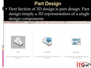
Web:www.infotechnogen.com
Email:info@infotechnogen.com
Contact :+91-9780096562
Address:Plot no 84-B Industrial Area Phase 5
Mohali
SOLIDWORKS
Introduction
 The Solid Works software is a solid modeling computer aided
design (CAD) and computer aided engineering (CAE) software
program that runs on Microsoft Windows. The SolidWorks is
produced by the Dassault Systems— a subsidiary of Dassault
Systèmes. Solid Works is currently used by over 2 million
engineers and designers at more than 165,000 .
 SOLIDWORKS Corporation was founded in
December 1993 by Massachusetts Institute of Technology
graduate Jon Hirschtick; Hirschtick used $1 million he had made
while a member of the MIT Blackjack Team to set up the
company. Initially based in Waltham, Massachusetts, USA,
Hirschtick recruited a team of engineers with the goal of
building 3D CAD software that was easy-to-use, affordable, and
available on the Windows desktop. Operating later from
Concord, Massachusetts, SOLIDWORKS released its first
product SolidWorks 95, in 1995.[5][6] In 1997 Dassault, best
known for its CATIA CAD software, acquired SolidWorks for
$310 million in stock.
Introduction
 SolidWorks, 3D PartStream.NET, 3D Content Central,
 eDrawings, and the eDrawings logo are registered trademarks
 and FeatureManager is a jointly owned registered trademark of
 DS SolidWorks.
 CircuitWorks, Feature Palette, FloXpress, PhotoWorks,
 TolAnalyst, and XchangeWorks are trademarks of DS
 SolidWorks.
 FeatureWorks is a registered trademark of Geometric Software
 Solutions Ltd.
 SolidWorks 2011, SolidWorks Enterprise PDM, SolidWorks
 Simulation, SolidWorks Flow Simulation, and eDrawings
 Professional are product names of DS SolidWorks.
Contents
 Part Design
2D design (Sketch) , 3D design
(Features) , Part design consider
in the part design section
 Assembly Design
Assembling of two or more than
two parts consider in this section
 Drawing
Designing with standards is
consider in the drawing section
Sketch :-
Using Interface : In three dimensional software we need to
select an interface as working space.SolidWorks give three
different planes to choose as a working place.
Create a New Part Document
1 Create a new part. Click New on the Standard toolbar.
The New SolidWorks Document dialog box appears.
2 Click theTutorial tab.
3 Select the Part icon.
4 Click OK.
A new part document window appears.
Base Feature
The Base feature requires:
Sketch plane – Front (default plane)
Sketch profile – 2D Rectangle
Feature type – Extruded boss feature
Open a Sketch
1 Click to select the Front plane in the Feature
Manager design tree.
2 Open a 2D sketch. Click Sketch on the Sketch toolbar.
Confirmation Corner
When many SolidWorks commands are
active, a symbol or a set of symbols
appears in the
upper right corner of the graphics area. This
area is called the Confirmation Corner.
Sketch Indicator
When a sketch is active, or open, a
symbol appears in the confirmation corner that
looks like the Sketch tool. It provides a
visual reminder that you are active in a
sketch.
Clicking this symbol exits the sketch
saving your changes.
Clicking the red X exits the sketch
discarding your changes.
When other commands are active, the
confirmation corner displays two
symbols: a check mark and an X. The
check mark executes the current
command. The X cancels the command.
Sketch Commands
 Line
 Circle
 Arc
 Ellipse
 Rectangle
 Spline
 Fillet
 Slot
Making Cylinder
First of all we need a 2D sketch and after that it will
converted into a 3D design .
3D Feature Commands
 Extrude
 Swept
 Revolve
 Loft
 Extruded Cut
 Lofted Cut
 Revolve Cut
 Pattern
a. Linear Pattern
b. Circular Pattern
 Shell
 Rib
 Draft
3D Feature Commands
 Extrude
 Swept
 Revolve
 Loft
 Extruded Cut
 Lofted Cut
 Revolve Cut
 Pattern
a. Linear Pattern
b. Circular Pattern
 Shell
 Rib
 Draft
Part Design
 First Section of 3D design is part design. Part
design simply a 3D representation of a single
design components
Dimensioning in 2D
Assembly Design
 An assembly design consists of two or more
components assembled together at their respective
work positions using parametric relations. In
SolidWorks, these relations are called mates. These
mates allow you to constrain the degrees of freedom
of the components at their respective work positions.
 All components are
created as separate part documents, and then they
are placed and referenced in the assembly as
external components. In this type of approach, the
components are created in the Part mode and saved
as the (.sldprt) documents.
 After creating and saving all
components of the assembly, you need to start a new
assembly document (.sldasm) and insert the
components in it using the tools provided in the
Assembly mode. After inserting the components,
you can assemble
Assembly mates :
After designing the parts , now they are
assembled by using the mate technology. While doing
assembly the mates are the main point to be remember.
In Solid Works, mates can be applied using the Mate
Property Manager. Choose the Mate button in the
Assemble Command Manager or choose Insert >
Mate from the. Select a planar face, curved face, axis,
or a point on the first component and then select the
entity from the second component; the selected entities
will be highlighted. The names of the selected entities
will be displayed in the Entities to Mate selection box
of the Mate Selections rollout.
Drawing
 Drawing in Solid Works is done by the use of ISO
standards. In the drawing section firstly the size of
sheet is decided
After start the drawing section we have to select a drawing
sheet . Usually A4 sheet is used for the standard.
At the drawing sheet assembly parts design is used for
giving the details within standards . First the assemble
design is select from the save designs .
After selecting a assembly design the different views are
selected for detailing .
Views Placement :
a. Front View
b. Top View
c. Side View
d. Isometric View ( 3D View)
Dimensioning :
Scaling :
Dimensioning / Detailing
 After adding the different views on a drawing sheet next
thing to do is dimensioning and detailing. The proper
dimensioning of all view expect the isometric or 3D view .
Web:www.infotechnogen.com
Email:info@infotechnogen.com
Contact :+91-9780096562
Address:Plot no 84-B Industrial Area Phase 5
Mohali

Infotechnogen Solid works

  • 1.
  • 2.
  • 3.
    Introduction  The SolidWorks software is a solid modeling computer aided design (CAD) and computer aided engineering (CAE) software program that runs on Microsoft Windows. The SolidWorks is produced by the Dassault Systems— a subsidiary of Dassault Systèmes. Solid Works is currently used by over 2 million engineers and designers at more than 165,000 .  SOLIDWORKS Corporation was founded in December 1993 by Massachusetts Institute of Technology graduate Jon Hirschtick; Hirschtick used $1 million he had made while a member of the MIT Blackjack Team to set up the company. Initially based in Waltham, Massachusetts, USA, Hirschtick recruited a team of engineers with the goal of building 3D CAD software that was easy-to-use, affordable, and available on the Windows desktop. Operating later from Concord, Massachusetts, SOLIDWORKS released its first product SolidWorks 95, in 1995.[5][6] In 1997 Dassault, best known for its CATIA CAD software, acquired SolidWorks for $310 million in stock.
  • 4.
    Introduction  SolidWorks, 3DPartStream.NET, 3D Content Central,  eDrawings, and the eDrawings logo are registered trademarks  and FeatureManager is a jointly owned registered trademark of  DS SolidWorks.  CircuitWorks, Feature Palette, FloXpress, PhotoWorks,  TolAnalyst, and XchangeWorks are trademarks of DS  SolidWorks.  FeatureWorks is a registered trademark of Geometric Software  Solutions Ltd.  SolidWorks 2011, SolidWorks Enterprise PDM, SolidWorks  Simulation, SolidWorks Flow Simulation, and eDrawings  Professional are product names of DS SolidWorks.
  • 5.
    Contents  Part Design 2Ddesign (Sketch) , 3D design (Features) , Part design consider in the part design section  Assembly Design Assembling of two or more than two parts consider in this section  Drawing Designing with standards is consider in the drawing section
  • 6.
    Sketch :- Using Interface: In three dimensional software we need to select an interface as working space.SolidWorks give three different planes to choose as a working place. Create a New Part Document 1 Create a new part. Click New on the Standard toolbar. The New SolidWorks Document dialog box appears. 2 Click theTutorial tab. 3 Select the Part icon. 4 Click OK. A new part document window appears. Base Feature The Base feature requires: Sketch plane – Front (default plane) Sketch profile – 2D Rectangle Feature type – Extruded boss feature
  • 7.
    Open a Sketch 1Click to select the Front plane in the Feature Manager design tree. 2 Open a 2D sketch. Click Sketch on the Sketch toolbar.
  • 8.
    Confirmation Corner When manySolidWorks commands are active, a symbol or a set of symbols appears in the upper right corner of the graphics area. This area is called the Confirmation Corner. Sketch Indicator When a sketch is active, or open, a symbol appears in the confirmation corner that looks like the Sketch tool. It provides a visual reminder that you are active in a sketch. Clicking this symbol exits the sketch saving your changes. Clicking the red X exits the sketch discarding your changes.
  • 9.
    When other commandsare active, the confirmation corner displays two symbols: a check mark and an X. The check mark executes the current command. The X cancels the command.
  • 10.
    Sketch Commands  Line Circle  Arc  Ellipse  Rectangle  Spline  Fillet  Slot
  • 11.
    Making Cylinder First ofall we need a 2D sketch and after that it will converted into a 3D design .
  • 12.
    3D Feature Commands Extrude  Swept  Revolve  Loft  Extruded Cut  Lofted Cut  Revolve Cut  Pattern a. Linear Pattern b. Circular Pattern  Shell  Rib  Draft
  • 13.
    3D Feature Commands Extrude  Swept  Revolve  Loft  Extruded Cut  Lofted Cut  Revolve Cut  Pattern a. Linear Pattern b. Circular Pattern  Shell  Rib  Draft
  • 14.
    Part Design  FirstSection of 3D design is part design. Part design simply a 3D representation of a single design components
  • 15.
  • 18.
    Assembly Design  Anassembly design consists of two or more components assembled together at their respective work positions using parametric relations. In SolidWorks, these relations are called mates. These mates allow you to constrain the degrees of freedom of the components at their respective work positions.  All components are created as separate part documents, and then they are placed and referenced in the assembly as external components. In this type of approach, the components are created in the Part mode and saved as the (.sldprt) documents.  After creating and saving all components of the assembly, you need to start a new assembly document (.sldasm) and insert the components in it using the tools provided in the Assembly mode. After inserting the components, you can assemble
  • 19.
    Assembly mates : Afterdesigning the parts , now they are assembled by using the mate technology. While doing assembly the mates are the main point to be remember. In Solid Works, mates can be applied using the Mate Property Manager. Choose the Mate button in the Assemble Command Manager or choose Insert > Mate from the. Select a planar face, curved face, axis, or a point on the first component and then select the entity from the second component; the selected entities will be highlighted. The names of the selected entities will be displayed in the Entities to Mate selection box of the Mate Selections rollout.
  • 22.
    Drawing  Drawing inSolid Works is done by the use of ISO standards. In the drawing section firstly the size of sheet is decided
  • 23.
    After start thedrawing section we have to select a drawing sheet . Usually A4 sheet is used for the standard.
  • 24.
    At the drawingsheet assembly parts design is used for giving the details within standards . First the assemble design is select from the save designs .
  • 25.
    After selecting aassembly design the different views are selected for detailing . Views Placement : a. Front View b. Top View c. Side View d. Isometric View ( 3D View) Dimensioning : Scaling :
  • 26.
    Dimensioning / Detailing After adding the different views on a drawing sheet next thing to do is dimensioning and detailing. The proper dimensioning of all view expect the isometric or 3D view .
  • 28.