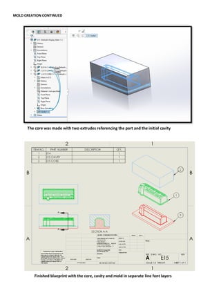
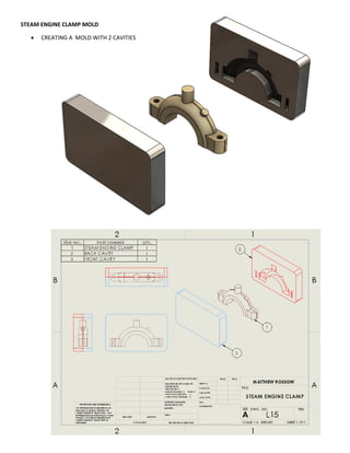
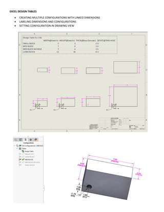
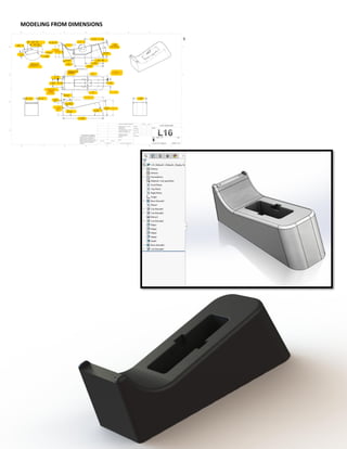
MATT ROSSOW
ADVANCEDSOLIDWORKS PORTFOLIO
(Work in progress)
CONTENTS:
 AUTOCAD DWG & DXF CONVERSIONS
 DESIGN LIBRARIES
 ADVANCED SURFACING - LOFTS
 PREPARING PARTS FOR MOLDS
 MOLD CREATION
 MODELING WITH EXCEL DESIGN TABLES
 TOP DOWN ASSEMBLIES
 WRITING SOLIDWORKS EQUATIONS
 ADVANCED SURFACING - GUIDE CURVE SWEEPS
 SHEET METAL COVER MODELING - TOP DOWN
 SHEET METAL TOOLS
 DESIGN LIBRARY ASSEMBLY TOOLS
 WELDMENTS, STRUCTURAL STEEL
 IGES/STEP IMPORT REPAIR & FEATUREWORKS
 INTERNAL VOLUME CALCULATION
DWG & DXF CONVERSIONS
 CONVERTING 2D AUTOCAD FILES INTO 3D SOLIDWORKS PARTS
Creating revolve of the section view after fully defining sketch
Opening original AutoCAD drawing into Solidworks and turning off extraneous layers
DWG & DXF CONVERSIONS CONTINUED
 LAYER PROPERTIES TO TURN ON/OFF UNECESSARY LAYERS
 USING MEASURE TOOL ON THE 2D SKETCH TO DETERMINE DIMENSIONS FOR RADIUSES AND CHAMFERS
 FULLY DEFINING CONVERTED SKETCHES
 MOVING SKETCHES RELATIVE TO ORIGIN SO THEY ARE IN SYNC WITH PART
Inserting splines and arcs relative to origin Adding the 53.15 degree chamfer defined on the print
DWG & DXF PATTERN CONVERSION
 CUTTING/ EXTRUDING DXF LOGOS, DRAWINGS AND DESIGNS INTO PARTS
DWG design provided to create a garden hose basket with walls .125 inches thick
DESIGN LIBRARIES
 SAVING DESIGNS INTO LIBRARIES
 APPLYING DESIGNS FROM LIBRARIES
A clip is pulled from thelibrary and applied to the cd case to save time when using complex repeat designs
Circle extrudes are created where the clips are to be placed
ADVANCED SURFACING - LOFTING A SPRAY BOTTLE
 GUIDE CURVES AND PROFILES FOR LOFTING
 SUPER SMOOTH CURVATURE CONTINUOUS FILLETS
 HELIX SPIRAL SWEEPS FOR THREADS
 PROJECTED CURVES
 CREATING LEAD INS FOR THREADS
 SURFACE CUT EXTRUDES
Creating profiles and guide curves for lofting Editing the guide curves & adding spline points
Zebra stripes to differentiate C-0, C-1 and C-2 continuity Curvature continuous fillets
ADVANCED SURFACING CONTINUED
Creating a sweep using the helix as the path Creating leadins via convert entity and revolve
Sweep using a projected curve as the path
Surface cut extrude for the bottle’s label placement
MODELING FROM SCHEMATIC/DIMENSIONS – LOFTING/SWEEPING
MOLD PREPARATION (MODIFYING PARTS FOR MOLD CREATION)
 DRAFT ANALYSIS TOOL
 ROLLBACK TO ADD DRAFT TO BASE EXTRUDE
 PARTING LINE DRAFT TO AVOID THINNING OF A FEATURE
 DRAFTING ALL OUTER FACES OF A FEATURE
 ADDING SETBACKS
Original mold received for prep viewed in draft analysis
Parting line draft added to avoid thinning smaller features
MOLD PREPARATION CONTINUED
Setbacks are added for the aluminum casting for extra thickness to avoid cracking
Adding draft to all outer faces of a flange
MOLD PREPARATION CONTINUED
Convert entities on top side of flange to extrude with draft and cover holes
Part ready for mold creation
MODELING FROM PRINT
 USING TRIGONOMETRY TO CALCULATE DIMENSIONS
 CREATING REFERENCE PLANES AT SPECIFIC HEIGHTS/ ANGLES
Part modeled from schematic. I caught a rounding error in the print. I will be creating a mold for this part.
MOLD CREATION
 CREATING MOLD CAVITIES & CORES IN AN ASSEMBLY
 CREATING LAYERS & EDITING COMPONENT LINE FONT
Using the cavity tool to create the mold with the part as the design component
Verifying the cavity was created with an explode
MOLD CREATION CONTINUED
The core was made with two extrudes referencing the part and the initial cavity
Finished blueprint with the core, cavity and mold in separate line font layers
STEAM ENGINE CLAMP MOLD
 CREATING A MOLD WITH 2 CAVITIES
EXCEL DESIGN TABLES
 CREATING MULTIPLE CONFIGURATIONS WITH LINKED DIMENSIONS
 LABELING DIMENSIONS AND CONFIGURATIONS
 SETTING CONFIGURATION IN DRAWING VIEW
MODELING FROM DIMENSIONS
MODELING PARTS WITH DESIGN TABLES
 CREATING VARIABLE DESIGN CONFIGURATIONS WITH LINKED DIMENSIONS AND EXCEL
TOP DOWN GEARBOX ASSEMBLY
 AN EXAM COMPLETED IN UNDER 20 MINUTES
 REAR CASTING & GASKET CREATED FROM SCRATCH INSIDE THE ASSEMBLY
 MECHANICAL MATE APPLIED TO GEARS
 ALL INTERIOR SURFACES FILLETED WITH DRAFT ON THE RIBS
 CREATED DRAWING IN EXPLODED VIEW WITH BALLOONS & BILL OF MATERIALS PER INSTRUCTIONS
MODELING 3D PRINTING TRAY FROM DIMENSIONS
WORKING WITH EQUATIONS IN SOLIDWORKS
 DISPLAYING & ASSIGNING DIMENSION NAMES
 CREATING EQUATIONS TO AUTOMATE TASKS
This equation automatically adjusts the rib copies along the length of the packaging mold when the
width is changed.
ADVANCED SURFACING – SWEEPING WITH GUIDE CURVES
 VARIABLE RADIUS FILLETS
 SPLIT LINE FEATURE
 DOME FEATURE
 REVERSE OFFSET EXTRUDED LOGO
Variable radius fillets for a smoother blend
Split line feature divides the surfaces allowing for
a flat ring and an inverse dome on the bottom
Profile, Back Guide Curve, Right Guide Curve & Path
TOP DOWN ASSEMBLY OF DESKTOP PC COVER WITH SHEET METAL TOOLS
 BASE FLANGE
 SETTING BEND ALLOWANCE K FACTOR (.34)
 MATERIAL OUTSIDE PROPAGATED MITRE FLANGE
The provided assembly of a PC Desktop is in
need of a cover modeled with sheet metal tools
Base Flange via converted entities with extra
.4 inch material on the bottom to be hemmed
A Mitre Flange (blue above) is created after
sketching on an edge perpendicular to our cover
and is then propagated
Hems are created at the bottom so the
case has no sharp corners
SHEET METAL ASSEMBLY CONTINUED
 FOLD/UNFOLD
 ADDING EXHAUST CUT EXTRUDES
 CREATING 1:1 CUSTOM SCALE PRINT WITH ORDINATE DIMENSIONS
 CREATING DXF OR DWG FILES FOR LASER MACHINING
The part is unfolded and exhaust vents are cut extruded
The drawing can be used to create a 1:1 scale print with ordinate dimensions to assist production
or it can be saved as a dxf/dwg to create the part
MODELING & UNFOLDING SHEET METAL PARTS
 RIP TOOL
 CONICAL SHEET METAL
 LOFTED BEND
MODELING FROM DIMENSIONS
 CONVERTING DWG & DXF IMAGES/LOGOS INTO SOLIDWORKS
The logo and text were initially DWG files brought in separately and superimposed
DESIGN LIBRARY ASSEMBLY
 ASSIGNING FILE LOCATIONS FOR DESIGN LIBRARIES
 MATE REFERENCE TOOL
 COMPONENT MIRRORING
 ADJUSTING RENDERING REFLECTIVITY & BRIGHTNESS
A mate reference was created for the fastening bolt
so it automatically mates properly when brought in
Model assembled in Solidworks
SURFACING TOOLS
 SKETCH PICTURE TOOL TO IMPORT JPEG
 3D PROJECTED CURVE VIA FRONT & RIGHT GUIDE CURVES
 SURFACE SWEEP
 SURFACE LOFT
 SURFACE KNIT
 SURFACE TRIM
These JPEG images were scaled and traced
in Solidworks to create the 3D model
Surface sweep using 3 point arc as profile, curve from right side
image as path and the projected curve as the guide curve
The Projected Curve and Surface Loft can be seen
above in blue
WELDMENTS
 STRUCTURAL MEMBERS
 ENDCAPS
 GUSSETS
 WELD BEADS
 INSERTING CUT LIST
IGES/STEP MODEL IMPORT REPAIR & FEATUREWORKS
 REPAIRING GAPS & FAULTY FACES IN IGES IMPORTS
 FEATUREWORKS TO CONVERT NON-INTELLIGENT MODELS INTO FEATURES
Before Matt
After Matt
INTERNAL VOLUME CALCULATION
 TASKED WITH MODELING BOTTLE & CALCULATING INTERNAL VOLUME
 USEFUL FOR INTRICATE DESIGNS WITH EXACT VOLUME REQUIREMENTS
 COMBINE TOOL UTILIZED WITH SUBTRACT OPTION
Boss extrude with merge unselected for separate bodies
INTERNAL VOLUME CALCULATION CONTINUED
The internal volume (if filled to the brim) = 11.53 cubic inches = 188.94 ml = 6.38 oz
Using the Combine tool with subtract option to select the inner volume
MODELING 5G PHONE BEZEL
 APPLIED R40 & R12 CURVED EDGES TANGENT TO .375R CORNERS
 OFFSET WALL THICKNESS AND EXTRUDED
 APPLIED DOME ON TOP COVER & SHELLED .06 UNIFORM WALL THICKNESS
 CUT EXTRUDE FOR SCREEN OPENING
 CUT-EXTRUDE FOR MIC SPEAKER
 CHAMFERED TOP OF BEZEL
 USED WIREFRAME TO DIMENSION/POSITION CHAMFERED INSERTS
Advanced portfolio

Advanced portfolio

  • 1.
    MATT ROSSOW ADVANCEDSOLIDWORKS PORTFOLIO (Workin progress) CONTENTS:  AUTOCAD DWG & DXF CONVERSIONS  DESIGN LIBRARIES  ADVANCED SURFACING - LOFTS  PREPARING PARTS FOR MOLDS  MOLD CREATION  MODELING WITH EXCEL DESIGN TABLES  TOP DOWN ASSEMBLIES  WRITING SOLIDWORKS EQUATIONS  ADVANCED SURFACING - GUIDE CURVE SWEEPS  SHEET METAL COVER MODELING - TOP DOWN  SHEET METAL TOOLS  DESIGN LIBRARY ASSEMBLY TOOLS  WELDMENTS, STRUCTURAL STEEL  IGES/STEP IMPORT REPAIR & FEATUREWORKS  INTERNAL VOLUME CALCULATION
  • 2.
    DWG & DXFCONVERSIONS  CONVERTING 2D AUTOCAD FILES INTO 3D SOLIDWORKS PARTS Creating revolve of the section view after fully defining sketch Opening original AutoCAD drawing into Solidworks and turning off extraneous layers
  • 3.
    DWG & DXFCONVERSIONS CONTINUED  LAYER PROPERTIES TO TURN ON/OFF UNECESSARY LAYERS  USING MEASURE TOOL ON THE 2D SKETCH TO DETERMINE DIMENSIONS FOR RADIUSES AND CHAMFERS  FULLY DEFINING CONVERTED SKETCHES  MOVING SKETCHES RELATIVE TO ORIGIN SO THEY ARE IN SYNC WITH PART Inserting splines and arcs relative to origin Adding the 53.15 degree chamfer defined on the print
  • 4.
    DWG & DXFPATTERN CONVERSION  CUTTING/ EXTRUDING DXF LOGOS, DRAWINGS AND DESIGNS INTO PARTS DWG design provided to create a garden hose basket with walls .125 inches thick
  • 5.
    DESIGN LIBRARIES  SAVINGDESIGNS INTO LIBRARIES  APPLYING DESIGNS FROM LIBRARIES A clip is pulled from thelibrary and applied to the cd case to save time when using complex repeat designs Circle extrudes are created where the clips are to be placed
  • 6.
    ADVANCED SURFACING -LOFTING A SPRAY BOTTLE  GUIDE CURVES AND PROFILES FOR LOFTING  SUPER SMOOTH CURVATURE CONTINUOUS FILLETS  HELIX SPIRAL SWEEPS FOR THREADS  PROJECTED CURVES  CREATING LEAD INS FOR THREADS  SURFACE CUT EXTRUDES Creating profiles and guide curves for lofting Editing the guide curves & adding spline points Zebra stripes to differentiate C-0, C-1 and C-2 continuity Curvature continuous fillets
  • 7.
    ADVANCED SURFACING CONTINUED Creatinga sweep using the helix as the path Creating leadins via convert entity and revolve Sweep using a projected curve as the path Surface cut extrude for the bottle’s label placement
  • 8.
  • 9.
    MOLD PREPARATION (MODIFYINGPARTS FOR MOLD CREATION)  DRAFT ANALYSIS TOOL  ROLLBACK TO ADD DRAFT TO BASE EXTRUDE  PARTING LINE DRAFT TO AVOID THINNING OF A FEATURE  DRAFTING ALL OUTER FACES OF A FEATURE  ADDING SETBACKS Original mold received for prep viewed in draft analysis Parting line draft added to avoid thinning smaller features
  • 10.
    MOLD PREPARATION CONTINUED Setbacksare added for the aluminum casting for extra thickness to avoid cracking Adding draft to all outer faces of a flange
  • 11.
    MOLD PREPARATION CONTINUED Convertentities on top side of flange to extrude with draft and cover holes Part ready for mold creation
  • 12.
    MODELING FROM PRINT USING TRIGONOMETRY TO CALCULATE DIMENSIONS  CREATING REFERENCE PLANES AT SPECIFIC HEIGHTS/ ANGLES Part modeled from schematic. I caught a rounding error in the print. I will be creating a mold for this part.
  • 13.
    MOLD CREATION  CREATINGMOLD CAVITIES & CORES IN AN ASSEMBLY  CREATING LAYERS & EDITING COMPONENT LINE FONT Using the cavity tool to create the mold with the part as the design component Verifying the cavity was created with an explode
  • 14.
    MOLD CREATION CONTINUED Thecore was made with two extrudes referencing the part and the initial cavity Finished blueprint with the core, cavity and mold in separate line font layers
  • 15.
    STEAM ENGINE CLAMPMOLD  CREATING A MOLD WITH 2 CAVITIES
  • 16.
    EXCEL DESIGN TABLES CREATING MULTIPLE CONFIGURATIONS WITH LINKED DIMENSIONS  LABELING DIMENSIONS AND CONFIGURATIONS  SETTING CONFIGURATION IN DRAWING VIEW
  • 17.
  • 18.
    MODELING PARTS WITHDESIGN TABLES  CREATING VARIABLE DESIGN CONFIGURATIONS WITH LINKED DIMENSIONS AND EXCEL
  • 19.
    TOP DOWN GEARBOXASSEMBLY  AN EXAM COMPLETED IN UNDER 20 MINUTES  REAR CASTING & GASKET CREATED FROM SCRATCH INSIDE THE ASSEMBLY  MECHANICAL MATE APPLIED TO GEARS  ALL INTERIOR SURFACES FILLETED WITH DRAFT ON THE RIBS  CREATED DRAWING IN EXPLODED VIEW WITH BALLOONS & BILL OF MATERIALS PER INSTRUCTIONS
  • 20.
    MODELING 3D PRINTINGTRAY FROM DIMENSIONS
  • 21.
    WORKING WITH EQUATIONSIN SOLIDWORKS  DISPLAYING & ASSIGNING DIMENSION NAMES  CREATING EQUATIONS TO AUTOMATE TASKS This equation automatically adjusts the rib copies along the length of the packaging mold when the width is changed.
  • 22.
    ADVANCED SURFACING –SWEEPING WITH GUIDE CURVES  VARIABLE RADIUS FILLETS  SPLIT LINE FEATURE  DOME FEATURE  REVERSE OFFSET EXTRUDED LOGO Variable radius fillets for a smoother blend Split line feature divides the surfaces allowing for a flat ring and an inverse dome on the bottom Profile, Back Guide Curve, Right Guide Curve & Path
  • 23.
    TOP DOWN ASSEMBLYOF DESKTOP PC COVER WITH SHEET METAL TOOLS  BASE FLANGE  SETTING BEND ALLOWANCE K FACTOR (.34)  MATERIAL OUTSIDE PROPAGATED MITRE FLANGE The provided assembly of a PC Desktop is in need of a cover modeled with sheet metal tools Base Flange via converted entities with extra .4 inch material on the bottom to be hemmed A Mitre Flange (blue above) is created after sketching on an edge perpendicular to our cover and is then propagated Hems are created at the bottom so the case has no sharp corners
  • 24.
    SHEET METAL ASSEMBLYCONTINUED  FOLD/UNFOLD  ADDING EXHAUST CUT EXTRUDES  CREATING 1:1 CUSTOM SCALE PRINT WITH ORDINATE DIMENSIONS  CREATING DXF OR DWG FILES FOR LASER MACHINING The part is unfolded and exhaust vents are cut extruded The drawing can be used to create a 1:1 scale print with ordinate dimensions to assist production or it can be saved as a dxf/dwg to create the part
  • 25.
    MODELING & UNFOLDINGSHEET METAL PARTS  RIP TOOL  CONICAL SHEET METAL  LOFTED BEND
  • 26.
    MODELING FROM DIMENSIONS CONVERTING DWG & DXF IMAGES/LOGOS INTO SOLIDWORKS The logo and text were initially DWG files brought in separately and superimposed
  • 27.
    DESIGN LIBRARY ASSEMBLY ASSIGNING FILE LOCATIONS FOR DESIGN LIBRARIES  MATE REFERENCE TOOL  COMPONENT MIRRORING  ADJUSTING RENDERING REFLECTIVITY & BRIGHTNESS A mate reference was created for the fastening bolt so it automatically mates properly when brought in Model assembled in Solidworks
  • 28.
    SURFACING TOOLS  SKETCHPICTURE TOOL TO IMPORT JPEG  3D PROJECTED CURVE VIA FRONT & RIGHT GUIDE CURVES  SURFACE SWEEP  SURFACE LOFT  SURFACE KNIT  SURFACE TRIM These JPEG images were scaled and traced in Solidworks to create the 3D model Surface sweep using 3 point arc as profile, curve from right side image as path and the projected curve as the guide curve The Projected Curve and Surface Loft can be seen above in blue
  • 29.
    WELDMENTS  STRUCTURAL MEMBERS ENDCAPS  GUSSETS  WELD BEADS  INSERTING CUT LIST
  • 30.
    IGES/STEP MODEL IMPORTREPAIR & FEATUREWORKS  REPAIRING GAPS & FAULTY FACES IN IGES IMPORTS  FEATUREWORKS TO CONVERT NON-INTELLIGENT MODELS INTO FEATURES Before Matt After Matt
  • 31.
    INTERNAL VOLUME CALCULATION TASKED WITH MODELING BOTTLE & CALCULATING INTERNAL VOLUME  USEFUL FOR INTRICATE DESIGNS WITH EXACT VOLUME REQUIREMENTS  COMBINE TOOL UTILIZED WITH SUBTRACT OPTION Boss extrude with merge unselected for separate bodies
  • 32.
    INTERNAL VOLUME CALCULATIONCONTINUED The internal volume (if filled to the brim) = 11.53 cubic inches = 188.94 ml = 6.38 oz Using the Combine tool with subtract option to select the inner volume
  • 33.
    MODELING 5G PHONEBEZEL  APPLIED R40 & R12 CURVED EDGES TANGENT TO .375R CORNERS  OFFSET WALL THICKNESS AND EXTRUDED  APPLIED DOME ON TOP COVER & SHELLED .06 UNIFORM WALL THICKNESS  CUT EXTRUDE FOR SCREEN OPENING  CUT-EXTRUDE FOR MIC SPEAKER  CHAMFERED TOP OF BEZEL  USED WIREFRAME TO DIMENSION/POSITION CHAMFERED INSERTS