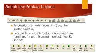
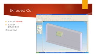
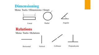
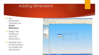
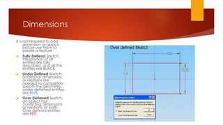
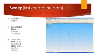
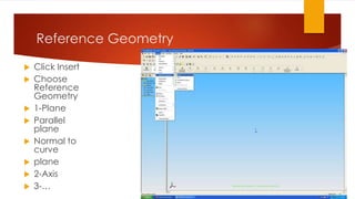
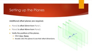
AMIT KAMBOJ
1512393
M-5
INTRODUCTION OF COMPUTER
DESIGNING
 CAD:
The CAD stands for the computer design may be defined as the
computer system which helps in creation, modification, analysis and
optimization.
 Specifications sets include:
 CAD Models
 Drawings (Assembly, Detail, Stress Reports)
 Bills-of-Material
 Instructions:
 Manufacturing
 Assembly
 Maintenance
 Usage
SOME COMMONLY USED DESINING
SOFTWARES
 AUTOCAD
 SOLIDWORKS
 PRO-E
 CATIA
 ANSYS
 SOLID EDGE
AUTOCAD
 AUTOCAD is 2-D and 3-D modeling software.
 It is developed by autodesk company.
 Autodesk is an USA based company.
 Its initial release on December 1982.
 John walker is the developer of AUTOCAD.
 It comes in India 1988.
SOLIDWORKS
 THIS IS A POWERFUL AND USER-FRIENDLY SOFTWARE TO
DESIGN 3D MODEL OF MECHANICAL PARTS AND
ASSEMBLYS,DRAWINGS TO MANUFACTURE , ANALYSIS AND
SO ON.
 ITS INITIAL RELEASE WAS IN 1995
 SOLIDWORKS IS CURRENTLY USED BY OVER 2 MILLION
ENGINEERS AND MORE THAN 165,000 COMPNIES
WORLDWIDE.
COMPARISON
AUTOCAD
 Most prefer for 2-D modeling.
 Assembly cannot be done.
 Simulation test cannot be done.
 Sheet metal,weldments,mold tools
cannot be done.
SOLIDWORKS
 Prefer for 3-d modeling.
 Assembly can be done.
 Simulation test can be done.
 All can be done.
BASIC COMMANDS USED IN DESINING
SOFTWARES
 Draw commands:
• Line
• Circle
• Rectangle
• Arc
• Ellipse
• Polyline
• Spline
Modify commands:
 Erase
 Copy
 Mirror
 Fillet
 Chamfer
 Offset Entities
 Rotate
 Extend
 Trim
 Scale
 Zoom
The SolidWorks Model
The SolidWorks model is made up of:
 Parts
 Assemblies
 Drawings
Sketch and Feature Toolbars
 To create any Sketch (drawing ) use the
sketch toolbar.
 Feature Toolbar: this toolbar contains all the
functions for creating and manipulating 3D
shapes
Design a Part
 Every part is composed of a sketch
and a feature
 1- Go to Sketch Mode and Draw a
2D sketch(sketch is a drawing that
it has no thickness like line, circle,
rectangle, arc,… )
 2- Go to Feature Mode, select one
of the appropriate commands to
create 3D model(such as Cube,
Cylinder, spring,…)
Extrude
 Extrude the
sketch
 1-click
Extruded
base
 2-Set End
Condition to
Blind
 3-Set Depth
to 10 mm
 Click OK.
Extruded Cut
 Click on Feature
 Click on
Extruded cut
(the preview)
Dimensioning
Menu: Tools->Dimensions->Smart
Linear Radial Angular
Relations
Menu: Tools->Relations
Horizontal Vertical Collinear Perpendicular
SolidWorks Exercise
Click on the RIGHT vertical line, then hold down
the CTRL button. Click the left vertical line. You
should see a list of available relations that you
can add to BOTH line. Let’s choose EQUAL and
VERTICAL. Click the green check when finished.
Do the same thing for the top and bottom
horizontal line, except add a horizontal relation.
2D Sketch
 After selecting
one of the main
plane, click on a
shape on Sketch
Toolbar(Rectangl
e)
 Now, by clicking
on the design
area and move
the pointer you
can draw the
sketch
Adding Dimensions
 Use
Dimension
Tool(click on
Smart
Dimesion)
 Select the
entities to
add the
dimensions
 Double click
on dimensions
to modify the
dimensions
Dimensions
It is not required to add
dimension on sketch
before use them to
create a feature
 Fully Defiend Sketch:
the position of all
entities are fully
described, and all the
entities are BLACK
 Under Defined Sketch:
additional dimensions
or relations are
needed to completely
specify the geometry,
under defiened entities
are BLUE
 Over Defiened Sketch,
an object has
conflicting dimensions
or relations, or both.
Over defined entities
are RED.
Over defined Sketch
Sweep(first create the path)
to move a profile along a Path
 In sketch
mode
 Select Front
Plane in
Feature
manager
 Draw the
path for ex.
By clicking
spline draw
like the
picture
Sweep(create the x-section)
 Now draw
another sketch
as the X-
section:
 Choose the
Top plane
 Draw the
profile in sketch
mode (cirlce)
Reference Geometry
 Click Insert
 Choose
Reference
Geometry
 1-Plane
 Parallel
plane
 Normal to
curve
 plane
 2-Axis
 3-…
Reference geometry
 a plane parallel to
the Front Plane
with a distance 10
mm
Setting up the Planes
Additional offset planes are required.
 Plane2 is offset 25mm from Plane1.
 Plane3 is offset 40mm from Plane2.
 Verify the positions of the planes.
 Click View, Planes.
 Double-click the planes to see their offset dimensions.
Loft Feature
 The Loft feature blends the 4 profiles to create the handle of
the chisel.
1. Click Lofted Boss / Base on the Features toolbar.
Creating the Loft Feature:
2. Select each profile.
Click on each sketch in the same relative
location – the right side.
3. Examine the preview curve.
The preview curve shows how the profiles will be
connected when the loft feature is created.
Creating the Loft Feature:
4. The sketches are listed in the Profiles box.
The Up/Down arrows are used to
rearrange the order of the profiles.
Creating the Loft Feature:
 Click OK .
ASSEMBLY
 3. Assembly Modeling
(1) Loading the Components
 Menu: Insert->Component
 ->Existing Part/Assembly
Defining Mates
 Menu: Insert->Mate
Drawing Template and Drawing
Format
Menu: File->New->Draw
THANKS

solidworks

  • 1.
  • 2.
    INTRODUCTION OF COMPUTER DESIGNING CAD: The CAD stands for the computer design may be defined as the computer system which helps in creation, modification, analysis and optimization.  Specifications sets include:  CAD Models  Drawings (Assembly, Detail, Stress Reports)  Bills-of-Material  Instructions:  Manufacturing  Assembly  Maintenance  Usage
  • 3.
    SOME COMMONLY USEDDESINING SOFTWARES  AUTOCAD  SOLIDWORKS  PRO-E  CATIA  ANSYS  SOLID EDGE
  • 4.
    AUTOCAD  AUTOCAD is2-D and 3-D modeling software.  It is developed by autodesk company.  Autodesk is an USA based company.  Its initial release on December 1982.  John walker is the developer of AUTOCAD.  It comes in India 1988.
  • 5.
    SOLIDWORKS  THIS ISA POWERFUL AND USER-FRIENDLY SOFTWARE TO DESIGN 3D MODEL OF MECHANICAL PARTS AND ASSEMBLYS,DRAWINGS TO MANUFACTURE , ANALYSIS AND SO ON.  ITS INITIAL RELEASE WAS IN 1995  SOLIDWORKS IS CURRENTLY USED BY OVER 2 MILLION ENGINEERS AND MORE THAN 165,000 COMPNIES WORLDWIDE.
  • 7.
    COMPARISON AUTOCAD  Most preferfor 2-D modeling.  Assembly cannot be done.  Simulation test cannot be done.  Sheet metal,weldments,mold tools cannot be done. SOLIDWORKS  Prefer for 3-d modeling.  Assembly can be done.  Simulation test can be done.  All can be done.
  • 8.
    BASIC COMMANDS USEDIN DESINING SOFTWARES  Draw commands: • Line • Circle • Rectangle • Arc • Ellipse • Polyline • Spline
  • 9.
    Modify commands:  Erase Copy  Mirror  Fillet  Chamfer  Offset Entities
  • 10.
     Rotate  Extend Trim  Scale  Zoom
  • 11.
    The SolidWorks Model TheSolidWorks model is made up of:  Parts  Assemblies  Drawings
  • 12.
    Sketch and FeatureToolbars  To create any Sketch (drawing ) use the sketch toolbar.  Feature Toolbar: this toolbar contains all the functions for creating and manipulating 3D shapes
  • 13.
    Design a Part Every part is composed of a sketch and a feature  1- Go to Sketch Mode and Draw a 2D sketch(sketch is a drawing that it has no thickness like line, circle, rectangle, arc,… )  2- Go to Feature Mode, select one of the appropriate commands to create 3D model(such as Cube, Cylinder, spring,…)
  • 14.
    Extrude  Extrude the sketch 1-click Extruded base  2-Set End Condition to Blind  3-Set Depth to 10 mm  Click OK.
  • 15.
    Extruded Cut  Clickon Feature  Click on Extruded cut (the preview)
  • 16.
    Dimensioning Menu: Tools->Dimensions->Smart Linear RadialAngular Relations Menu: Tools->Relations Horizontal Vertical Collinear Perpendicular
  • 17.
    SolidWorks Exercise Click onthe RIGHT vertical line, then hold down the CTRL button. Click the left vertical line. You should see a list of available relations that you can add to BOTH line. Let’s choose EQUAL and VERTICAL. Click the green check when finished. Do the same thing for the top and bottom horizontal line, except add a horizontal relation.
  • 18.
    2D Sketch  Afterselecting one of the main plane, click on a shape on Sketch Toolbar(Rectangl e)  Now, by clicking on the design area and move the pointer you can draw the sketch
  • 19.
    Adding Dimensions  Use Dimension Tool(clickon Smart Dimesion)  Select the entities to add the dimensions  Double click on dimensions to modify the dimensions
  • 20.
    Dimensions It is notrequired to add dimension on sketch before use them to create a feature  Fully Defiend Sketch: the position of all entities are fully described, and all the entities are BLACK  Under Defined Sketch: additional dimensions or relations are needed to completely specify the geometry, under defiened entities are BLUE  Over Defiened Sketch, an object has conflicting dimensions or relations, or both. Over defined entities are RED. Over defined Sketch
  • 21.
    Sweep(first create thepath) to move a profile along a Path  In sketch mode  Select Front Plane in Feature manager  Draw the path for ex. By clicking spline draw like the picture
  • 22.
    Sweep(create the x-section) Now draw another sketch as the X- section:  Choose the Top plane  Draw the profile in sketch mode (cirlce)
  • 24.
    Reference Geometry  ClickInsert  Choose Reference Geometry  1-Plane  Parallel plane  Normal to curve  plane  2-Axis  3-…
  • 25.
    Reference geometry  aplane parallel to the Front Plane with a distance 10 mm
  • 26.
    Setting up thePlanes Additional offset planes are required.  Plane2 is offset 25mm from Plane1.  Plane3 is offset 40mm from Plane2.  Verify the positions of the planes.  Click View, Planes.  Double-click the planes to see their offset dimensions.
  • 27.
    Loft Feature  TheLoft feature blends the 4 profiles to create the handle of the chisel. 1. Click Lofted Boss / Base on the Features toolbar.
  • 28.
    Creating the LoftFeature: 2. Select each profile. Click on each sketch in the same relative location – the right side. 3. Examine the preview curve. The preview curve shows how the profiles will be connected when the loft feature is created.
  • 29.
    Creating the LoftFeature: 4. The sketches are listed in the Profiles box. The Up/Down arrows are used to rearrange the order of the profiles.
  • 30.
    Creating the LoftFeature:  Click OK .
  • 31.
    ASSEMBLY  3. AssemblyModeling (1) Loading the Components  Menu: Insert->Component  ->Existing Part/Assembly
  • 32.
  • 33.
    Drawing Template andDrawing Format Menu: File->New->Draw
  • 34.