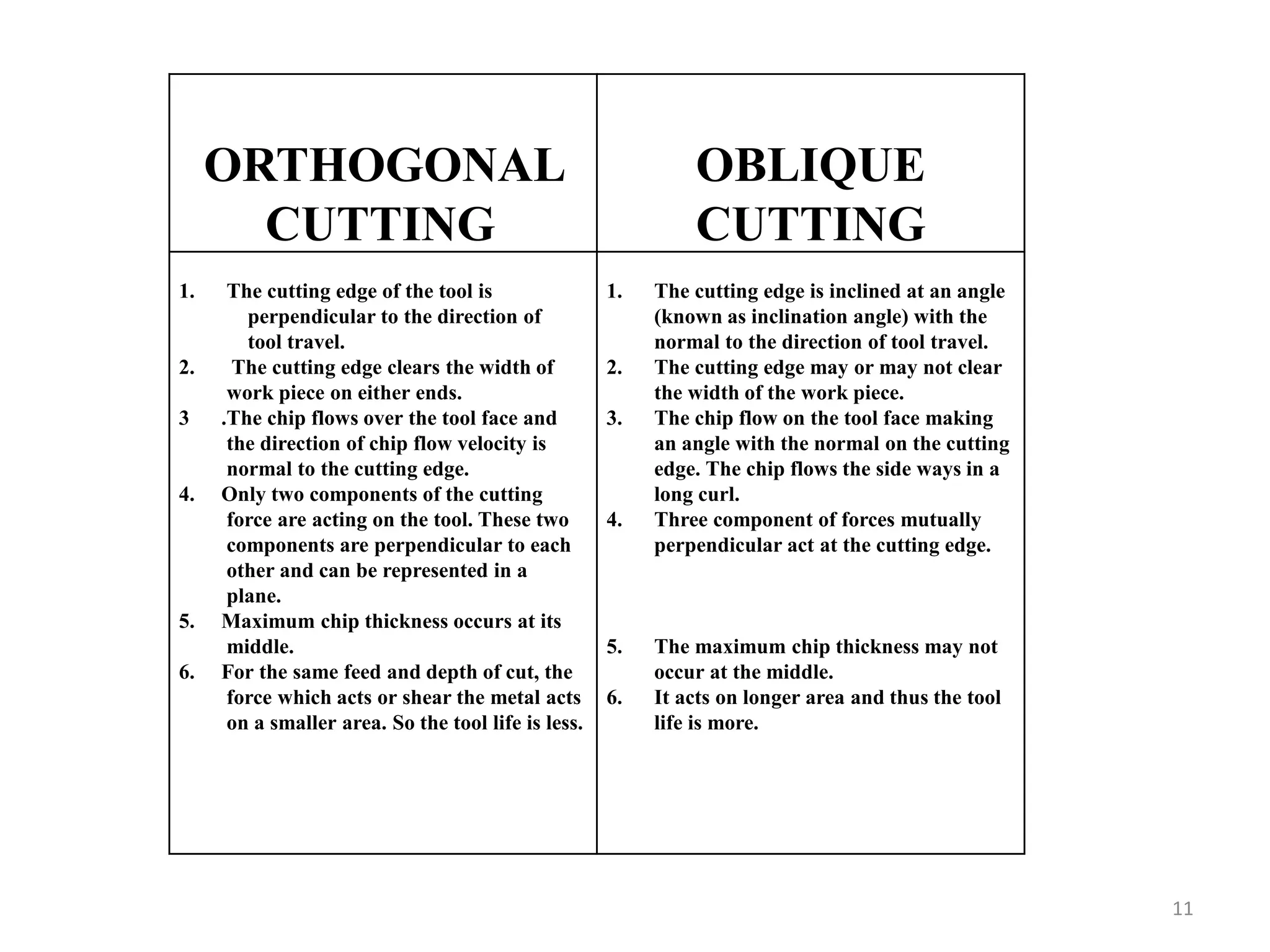
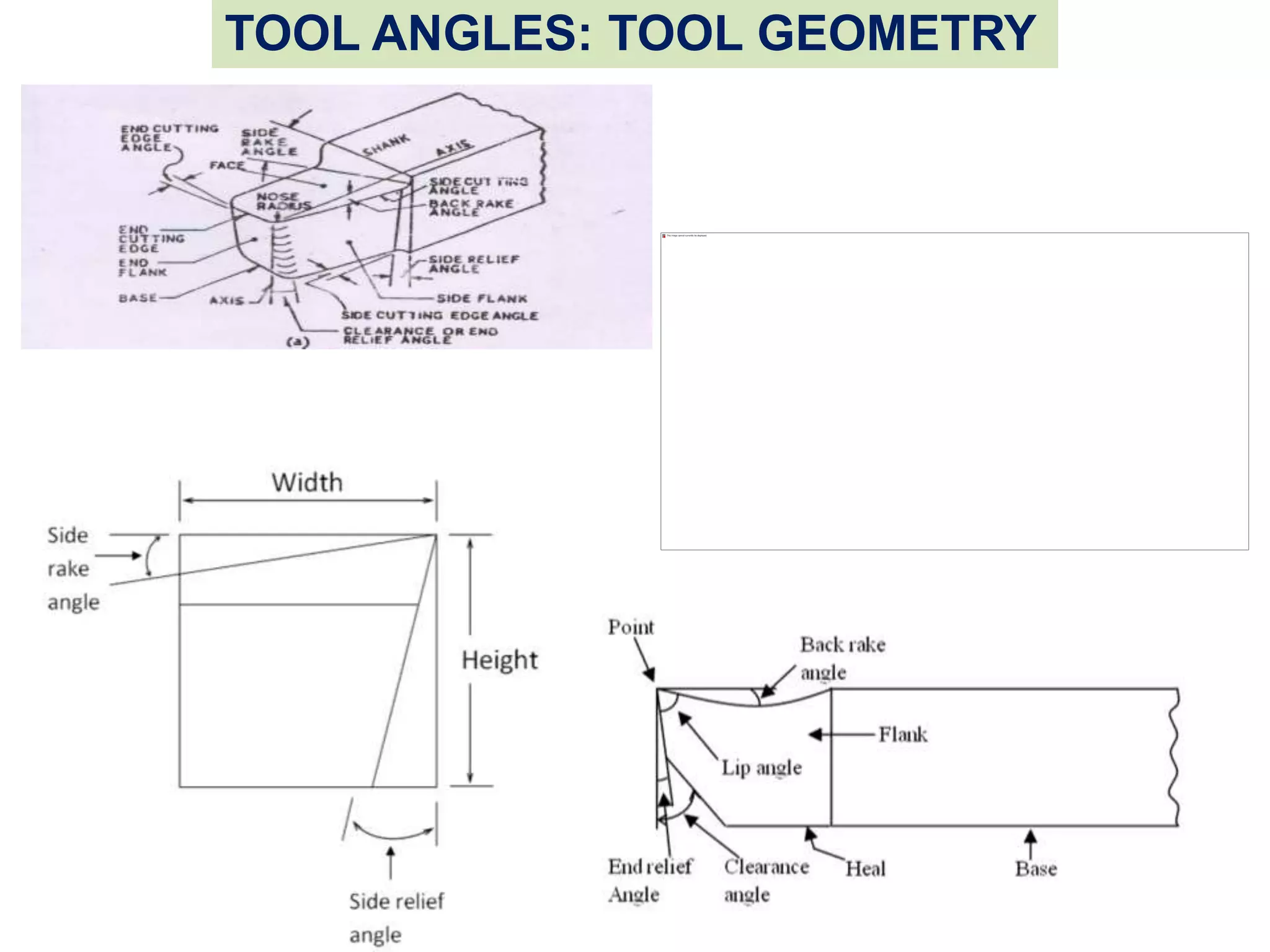
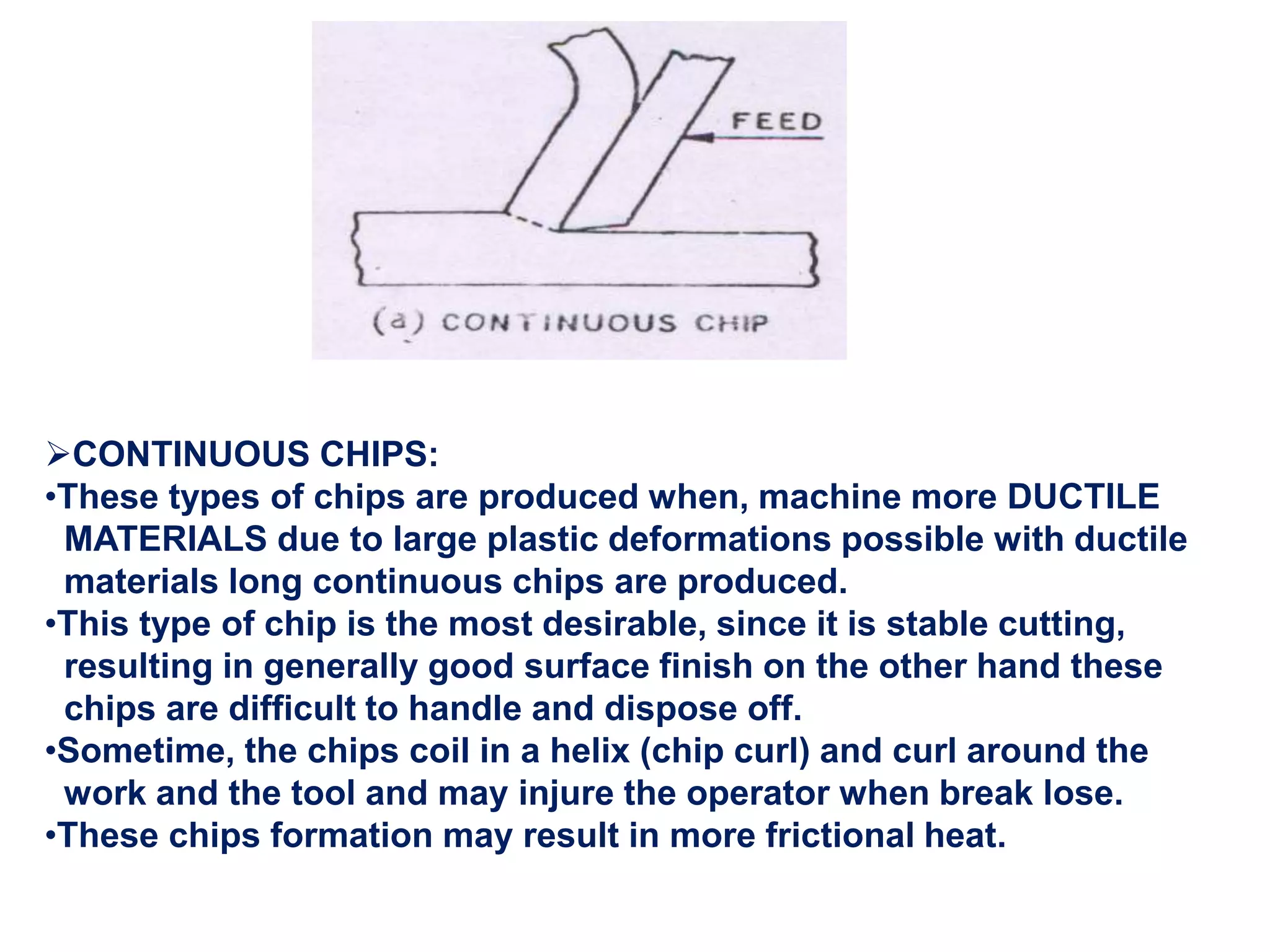
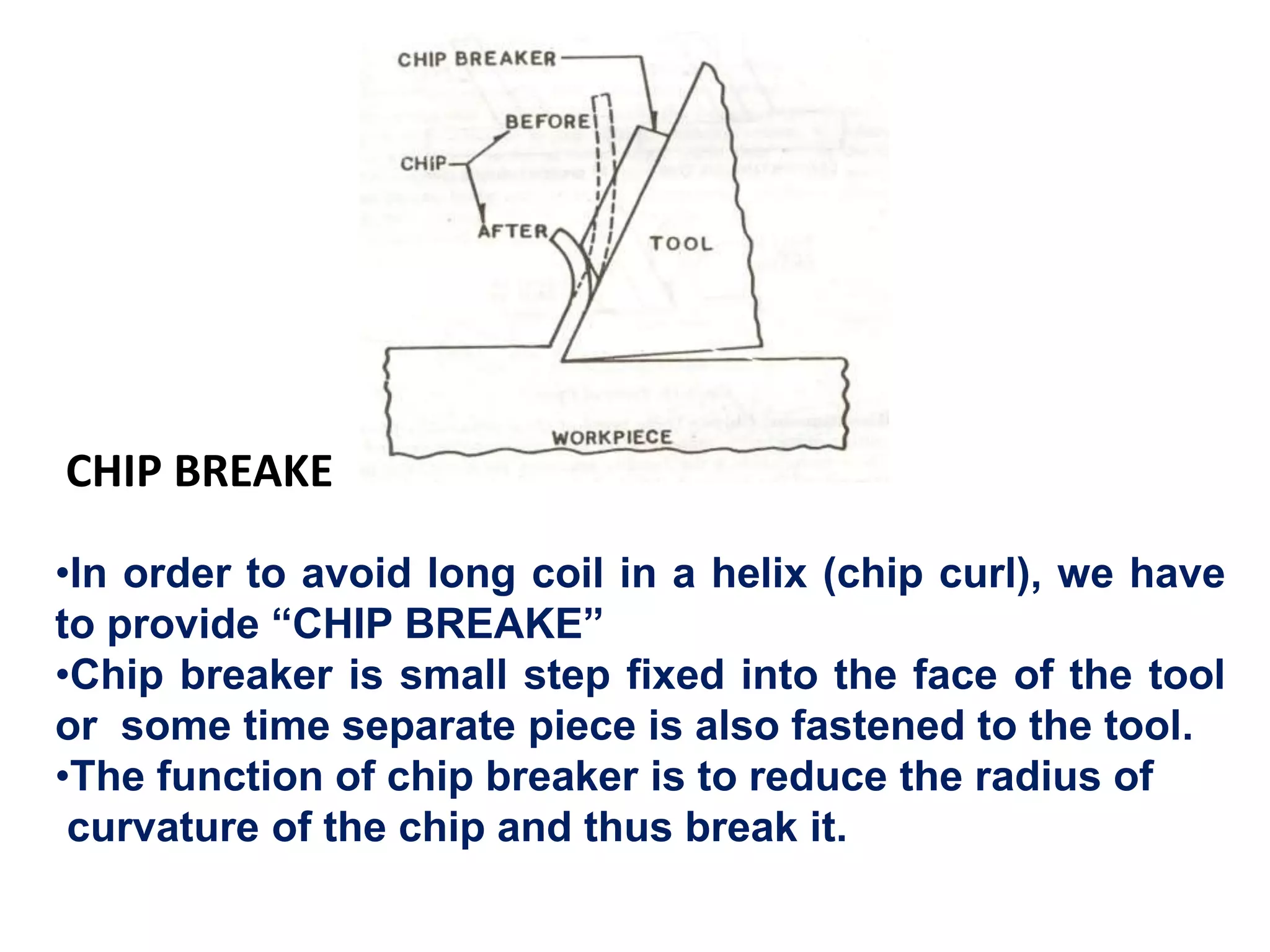
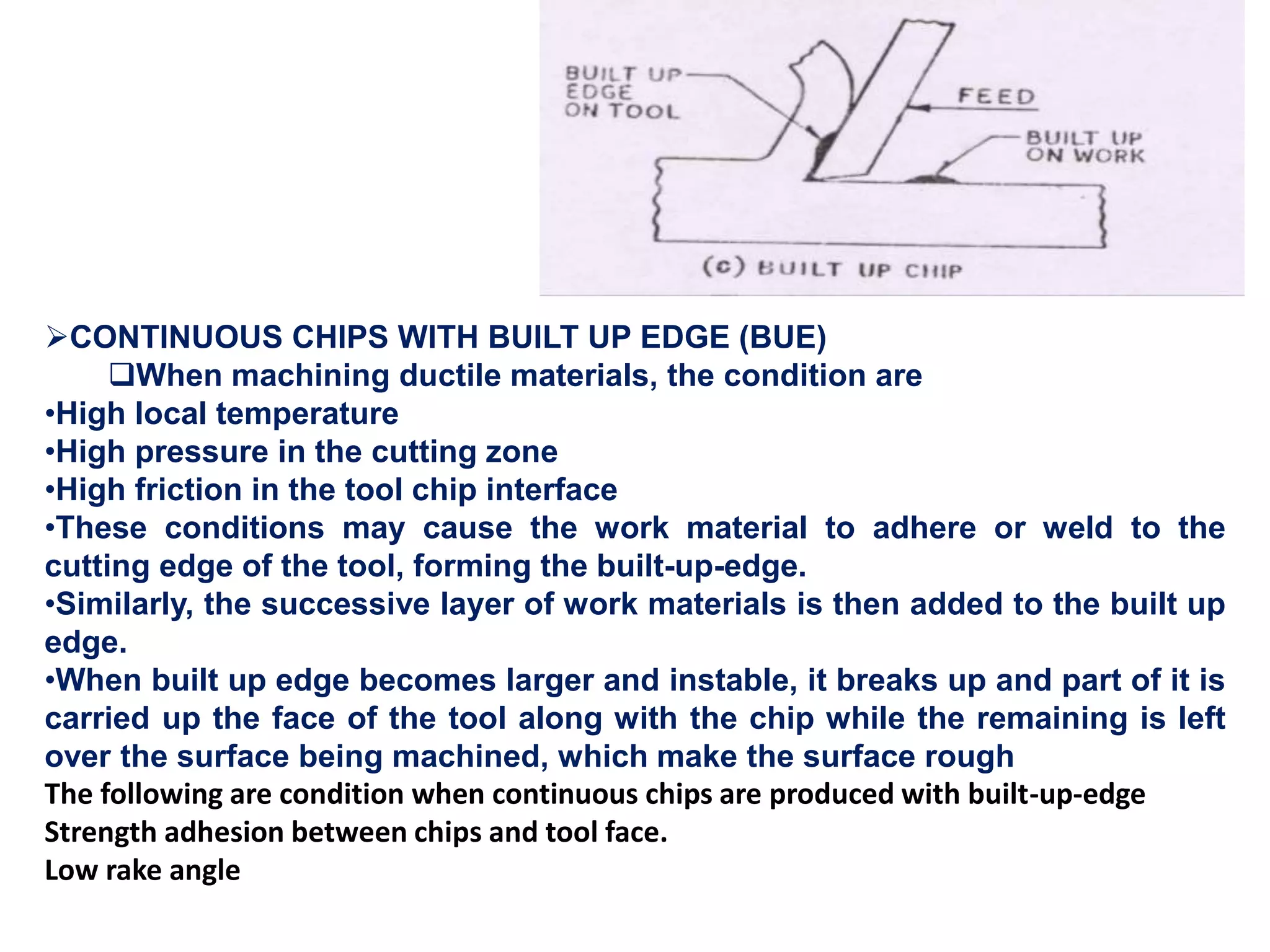
This slide is all about Metal cutting and Machining tools insights. It covers Mechanics of metal cutting, orthogonal and oblique machining, Tools geometry, Types of Chips, and Tools Signature.
This document discusses the theory of metal cutting. It covers topics such as tool geometry, chip formation, types of chips, tool wear, cutting fluids, and tool material selection. It describes the two main types of metal cutting processes as orthogonal and oblique cutting. Orthogonal cutting involves two forces while oblique cutting involves three forces. Chip formation occurs through shear deformation of the work material. The main types of chips are continuous, discontinuous, continuous with BUE, and serrated. Continuous chips form under conditions like small chip thickness and high cutting speed, while discontinuous chips occur when machining brittle materials.
Metal cutting involves removing unwanted material from a workpiece. In orthogonal cutting, the cutting tool edge is perpendicular to the direction of motion, so chip flow is perpendicular to the cutting edge. In oblique cutting, the cutting tool edge is at an angle to the direction of motion, so chip flow is sideways. Orthogonal cutting results in higher heat concentration, shorter tool life, and poorer surface finish than oblique cutting. Oblique cutting is used for most industrial processes like drilling and milling.
This presentation contains various aspects of metal cutting like mechanics of chip formation, single point cutting tool, chip breakers, types of chips,etc
- The document discusses heat generation in machining and its effects, temperature measurement techniques, types and functions of cutting fluids, and economics of metal cutting operations.
- Heat is generated in three zones during machining: the primary deformation zone, tool-chip interface, and tool-workpiece interface. Heat depends on factors like material properties and cutting parameters.
- High temperatures can damage tools and workpieces. Cutting fluids help reduce temperatures by conduction and convection of heat away from the cutting zone.
- Temperature is commonly measured using tool-workpiece thermocouples, which generate electrical signals related to temperature at the cutting interface.
This document discusses single point cutting tools. It describes the types of tools, tool geometry including angles and designations. It explains the effects that varying the back rake angle, side rake angle, relief angle, cutting edge angle, and nose radius have on machining. Finally, it lists common tool materials and provides brief conclusions and references.
The document discusses the shaper machine, which is a reciprocating machine tool used to produce flat surfaces. It has a ram, tool head, and table. The tool head cuts on the forward stroke and returns idle on the back stroke. Flat surfaces can be made horizontally, vertically, or at angles based on the movement of the tool head and table. Shapers are classified based on ram travel direction and cutting stroke action. Other machine tools discussed include the planer, slotter, drilling machines, and broaching machines.
The document discusses machining processes and cutting tools. It provides definitions of machining and cutting tools. It describes:
- The importance of machining processes in manufacturing precise parts.
- Objectives of machining like high material removal rate and surface finish, low tool and power costs.
- Classification of cutting tools based on how relative motion is provided between tool and workpiece.
- Key terms related to cutting tool geometry like rake angle, relief angle, and their influence on tool strength and chip removal.
- Mechanism of chip formation and different types of chips produced.
To introduce machining process
To understand mechanics of chip formation
To study important parameters of metal machining
To understand methods of machining
Fundamentals of Metal cutting and Machining Processes
MACHINING OPERATIONS AND MACHINING TOOLS
Turning and Related Operations
Drilling and Related Operations
Milling
Machining Centers and Turning Centers
Other Machining Operations
High Speed Machining
The document discusses the mechanics of metal cutting. It covers topics such as cutting models, turning forces, power and energies, tool terminology, cutting geometry, material removal rate, orthogonal and oblique cutting models, turning and facing forces, velocities, cutting forces, the merchant's circle diagram, stresses, power, specific cutting energy, and violations of orthogonal cutting models. It provides the theoretical framework for understanding metal cutting and machining processes.
This document provides an overview of various machining processes including turning, drilling, and milling. It describes the key operations for each process and common machine tools used. Turning operations like facing and threading are performed on lathes. Drilling and related operations like reaming and tapping are usually done on drill presses. Milling can be classified as peripheral or face milling and is commonly done on knee-and-column or bed type milling machines. The document outlines the basic mechanics and applications of various machining techniques.
Unit 2 Machinability, Cutting Fluids, Tool Life & Wear, Tool MaterialsMechbytes
Concept of machinability, machinability index, factors affecting machinability
Different mechanism of tool wear types of tool wear (crater, flank etc.), Measurement and control of tool wear
Concept of tool life, Taylor's tool life equation (including modified version)
Different tool materials and their applications including effect of tool coating
Introduction to economics of machining
Cutting fluids: types, properties, selection and application methods
This document provides an overview of various machining operations including turning, drilling, milling, and others. It defines machining as a material removal process using sharp cutting tools. The main machining operations covered are turning operations on lathes such as facing, contour turning, and threading. Drilling operations like through holes, blind holes, reaming and tapping are also discussed. Milling operations like peripheral milling, face milling, end milling, and contour milling are summarized. The document also briefly covers other operations like shaping, planning, broaching, and sawing. It includes diagrams to illustrate the different operations.
Tool wear and failure can occur through three modes: fracture, temperature failure, or gradual wear. Gradual wear is preferred as it leads to the longest tool life. Wear occurs primarily at the rake face (crater wear) and flank face (flank wear) through mechanisms such as abrasion, adhesion, diffusion, chemical reactions, and plastic deformation. Tool life is defined as the cutting time until a certain wear criteria is reached, such as 0.5mm flank wear. The Taylor tool life equation describes the relationship between cutting speed, tool life, and material properties.
This document discusses tool wear, tool life, and machinability. It defines tool life as the useful cutting time before tool failure or need for resharpening. Tool wear is caused by various mechanisms like abrasion, diffusion, and plastic deformation, and is measured by flank and crater wear. Machinability is determined by factors like surface finish, tool life, cutting forces, and chip control. The machinability of different materials depends on their properties and varies significantly. Cutting fluids are used to decrease power needs, increase heat dissipation, and improve other machinability factors.
signature of single point cutting toolVaibhav Kadu
This document discusses tool signatures and different tool geometry systems. It provides information on:
1) The objective is to explain tool signatures, how tool angles affect machining, and why understanding signatures is important.
2) Tool signatures specify the key angles of a cutting tool in a standardized way. They indicate the active angles during cutting.
3) Three common tool geometry systems are described - ASA, ORS, and NRS. They each define tool angles differently based on different reference planes.
this is 2nd presentation of manufacturing processes in this presentation we discuss in detail about the theory of metal cutting, machiening processes,cutters etc
This document discusses different types of cutting tool materials and their properties. It covers seven main types of toolbit materials including high-speed steel, cast alloys, cemented carbides, ceramics, cermets, cubic boron nitride and polycrystalline diamond. The key properties for cutting tools are hardness, wear resistance, shock resistance, shape/configuration. Cemented carbides are widely used and offer high hardness, wear resistance and can operate at high speeds without losing sharpness. Coatings like titanium carbide and nitride and aluminum oxide are used to improve wear resistance at different speeds. Tool geometry including side relief, side clearance, rake angles and nose radius are also covered.
This document provides information about various machining processes and machine tools. It describes machining as a metal removing process using machine tools and cutting tools. Lathe machines are commonly used to produce cylindrical surfaces and other operations like turning, drilling, boring, etc. Other machine tools discussed include milling machines, drilling machines, grinding machines, shaping machines, and planning machines. The document provides detailed descriptions of various operations that can be performed on these machines.
The document discusses various topics related to machining processes including:
- The objectives of understanding machining processes and estimating machining time and costs.
- The mechanics of chip formation during metal cutting using single-point cutting tools.
- Factors that influence tool life such as cutting speed, feed rate, depth of cut, tool geometry, and work material.
- Different types of chips produced during machining such as continuous, discontinuous, and chips with a built-up edge.
- Properties required for cutting tool materials including hardness, wear resistance, toughness, thermal conductivity and elements commonly used.
- Common cutting tool materials including high-carbon steel, high-speed steel, cemented carbides
This document discusses chip formation and cutting tool geometry in metal cutting operations. It describes the mechanics of chip formation, where a wedge-shaped tool exerts pressure on the workpiece, inducing shear deformation and removing material in the form of chips. The types of chips formed depend on whether the material is ductile or brittle. Continuous, discontinuous, and continuous chips with built-up edges are discussed. The document also outlines the geometry of single point cutting tools, designation systems, types of rakes, orthogonal and oblique cutting methods, forces on tools, and the purpose and types of chip breakers used.
This document discusses cutting tools used in machining processes. It defines a cutting tool as any tool that removes metal by shear deformation. Cutting tools must be harder than the material cut and withstand heat. There are two main types: single point and multi-point tools. Single point tools have one cutting edge while multi-point tools have more than two edges, such as milling cutters and drills. Cutting tool materials include high-speed steel, carbides, ceramics, and diamonds. The geometry of single point tools is defined by angles such as back rake, side rake, end relief, and side relief angles, as well as nose radius.
This document provides information about milling machines and milling operations. It describes the major parts and differences between horizontal and vertical milling machines. Various milling operations like face milling, end milling and slot milling are explained along with principles of up and down milling. Different types of milling cutters are classified and their applications discussed. Specifications of milling machines like worktable size, movements in X, Y and Z directions and motor power are also covered.
This chapter aims to provide basic backgrounds of different types of machining processes and highlights on an understanding of important parameters which affects machining of metals with their chip removals.
Metal cutting or Machining is the process of producing workpiece by removing unwanted material from a block of metal. in the form of chips. This process is most important since almost all the products get their final shape and size by metal removal. either directly or indirectly.
The major drawback of the process is loss of material in the form of chips. In this chapter. we shall have a fundamental understanding of the basic metal process.
The document provides information about tool wear and tool life in machining processes. It discusses how tool wear occurs due to forces, temperature, and sliding action during cutting. The three main types of tool wear are flank wear, crater wear, and chipping. Flank wear is caused by abrasion from hard particles in the workpiece while crater wear results from high temperatures and diffusion at the tool-chip interface. Maintaining optimal cutting conditions and tool geometry can increase tool life. The document also covers tool materials, machinability factors, cutting fluids, machining forces, and lathe operations such as turning, facing, and threading.
Shaping, planing and slotting operationssabry said
This document provides information about shaping, planning and slotting operations. It discusses the key differences between these processes, describes the machines used such as shapers and planers, and covers operating conditions like cutting speed, feed, depth of cut, and material removal rate. It also includes examples of problems calculating machining time and cost for specific shaping and planning jobs.
1) The document discusses metal cutting processes and machine tools. It describes different types of machining operations like turning, milling, drilling etc.
2) It explains concepts like shear angle, cutting forces, tool geometry specifications and factors affecting chip formation. Diagrams of tool geometry and forces on cutting tool are provided.
3) Equations to calculate shear angle, cutting forces and power are derived based on Merchant's metal cutting theory which involves minimum energy principle and assumes work material behaves plastically.
Single point cutting tools have a single cutting edge used to remove material from a workpiece. They are used in lathe and shaper machines for operations like turning, facing, and boring. The tool has a shank, rake surface, flank surface, and a single cutting edge where the rake and flank surfaces intersect. Rake angle, which indicates the orientation of the rake surface, can be positive, negative, or zero, and influences factors like required cutting force, tool life, and machinability.
Mechanics of chip formation, single point cutting tool, forces in machining, Types of chip, cutting
tools– nomenclature, orthogonal metal cutting, thermal aspects, cutting tool materials, tool wear,
tool life, surface finish, cutting fluids and Machinability
1. The document discusses the theory of metal cutting, including mechanics of chip formation, types of chips, cutting tool materials, tool wear, and other related topics.
2. It describes the different types of tool wear that can occur, including flank wear which results from the gradual wearing away of the cutting edge, and crater wear.
3. The key factors that influence chip formation and tool wear are also examined, such as material properties, cutting conditions, tool geometry, and choice of cutting tool material.
Cutting processes remove material from a workpiece's surface by producing chips. Common machining operations include turning, cutting off, slab milling, and end milling. The objective of metal cutting is quick material removal, high surface finish, economy in tool cost, less power consumption, and minimum cycle time. Chips can be either discontinuous or continuous, depending on factors like tool geometry, cutting conditions, and material properties. Cutting forces include cutting, friction, and shear forces. Power in cutting is dissipated in shearing and at the tool-chip interface. High temperatures generated during cutting can adversely affect tool life and workpiece properties.
This document provides an overview of fundamental machining concepts. It defines machining as a process of finishing workpieces by gradually removing excess material in the form of chips using cutting tools. Key concepts discussed include the geometry of single point cutting tools, tool angles like rake and clearance angles, chip formation, different types of chips, and shear plane and angle. It also discusses tool signatures and terminology. The document aims to provide elementary treatment of metal cutting theory.
Single point cutting tools have a shank, cutting part, and various angles that define their geometry. The rake and relief angles affect cutting forces and tool life. Rake angles control cutting forces, while relief angles provide clearance and prevent rubbing. Tool wear occurs through adhesion, abrasion, and diffusion, degrading the cutting edge over time. Tool life is measured by various criteria like cutting time or material removed before failure. Tool life decreases with higher cutting speeds and increases with lower depths of cut and feed rates. Proper selection of tool geometry and cutting conditions can optimize tool life.
This document summarizes cutting tools used in machining processes. It discusses single point and multi-point cutting tools. Single point tools have a single cutting edge, such as lathe and planer tools, while multi-point tools have two or more cutting edges like milling cutters and drills. The document describes the geometry of single point tools including the shank, flank, face, base, heel, nose, and cutting edges. It also discusses the various tool angles used in single point tools and provides examples of machines that use multi-point tools like milling machines and broaching machines. Finally, it covers tool wear, failure modes, and compares characteristics of single and multi-point cutting tools.
The document discusses the theory of metal cutting. It defines key terms like cutting tool, machine tool, and chip formation. It describes different types of chips that can form during cutting like continuous, discontinuous, and built-up edge chips. It explains the orthogonal cutting model and important angles of cutting tools like rake angle and clearance angle. It discusses the chip formation process and variables that influence forces and power requirements during cutting.
1. The document discusses the theory of metal cutting, including the chip formation process, types of chips, tool angles, tool wear mechanisms, tool materials, and cutting fluids.
2. Key aspects covered include the orthogonal cutting model, factors that influence chip type like tool angles and speeds/feeds, how tool angles impact forces and tool life, and common tool materials like HSS and cemented carbides and their characteristics.
3. Cutting fluids are discussed as being important to reduce heat at the tool-work interface and lubricate the process to increase tool life and improve surface finish. Their properties and common types used are also summarized.
This document discusses the theory and mechanics of metal cutting. It begins by defining metal cutting as removing unwanted material from a workpiece through cutting, abrasion, or non-traditional processes. It then covers the basics of orthogonal and oblique metal cutting, tool geometry including rake and relief angles, and different types of chips that can form. The document also discusses important considerations for metal cutting like cutting speed, feed rate, depth of cut, and tool materials commonly used including high-speed steel, cemented carbides, and ceramics.
M.P- II-UNIT I -THEORY OF METAL CUTTING.pptMohanumar S
This document provides an overview of the objectives and outcomes for the course 20ME403 Manufacturing Process - II. The key topics covered include the theory of metal cutting, construction and operation of various machine tools like lathes, milling machines, and grinding machines. It also discusses gear manufacturing processes and CNC programming. The objectives are for students to understand metal cutting principles, machine tool operations, and acquire the ability to apply these concepts in machining as well as develop CNC part programs.
This document provides information on metal cutting processes and machining technology. It discusses:
- The purpose, principles, and definition of machining as a process to produce parts to desired dimensions and surface finish through chip removal.
- Classification of metal cutting processes as orthogonal or oblique cutting. It also discusses cutting tool angles like back rake angle and relief angles.
- Factors that affect cutting forces like rake angle, feed rate, and depth of cut.
- Tool designation systems like ASA and common tool materials like high-speed steel and cemented carbide.
- The mechanism of chip formation and different chip types like continuous, discontinuous, and chips with built-up edge
The document discusses metal cutting and machining processes. It defines material removal processes as shaping operations that remove material from a work part to achieve a desired geometry. The two main types are machining, using a sharp cutting tool, and abrasive processes, using abrasive particles. Machining is important because it can cut a variety of materials and produce complex part shapes and features like threads and holes. However, it wastes material in chips and can be time consuming. The document then discusses chip formation mechanisms and types of chips produced from different materials and cutting conditions. It also defines tool elements, angles, and different types of single-point and multi-point cutting tools.
Cutting tools are used to remove metal from workpieces through shear deformation. There are two basic types: single-point and multiple-point tools. Single-point tools have a single dominant cutting edge and are used for turning, while multiple-point tools have more than one cutting edge and are used for drilling and milling. Cutting tools must be made of materials harder than the workpiece material and able to withstand the heat generated during machining. Common tool materials include high-speed steel, cemented carbides, ceramics, and polycrystalline diamond. Cutting tools must have properties like hardness, hot hardness, toughness, wear resistance, and ability to dissipate heat.
This document provides an overview of metal cutting theory and processes. It discusses orthogonal and oblique cutting, types of cutting tools including single point and multipoint tools, tool geometry and signatures. It also covers mechanics of metal cutting including shear angle and chip formation, tool materials, tool wear and tool life, factors affecting machining, and types of metal cutting processes and chips. Cutting fluid types and applications are also summarized.
This document discusses the theory of metal cutting. It covers topics such as orthogonal and oblique cutting, types of cutting tools including single-point and multipoint tools, tool geometry including rake angles and relief angles, mechanics of metal cutting including shear angle and chip formation, types of chips, tool wear and tool life, cutting fluids, and various metal cutting processes. Key points covered include shear angle significance in metal cutting, factors affecting metal cutting, and nomenclature used for describing single-point cutting tool geometry.
The document discusses tool specification and chip formation mechanisms. It begins by outlining the American System for specifying tool angles such as rake, relief, and cutting edge angles. It then explains how each angle impacts cutting forces and tool strength. The document also describes the mechanics of chip formation, defining shear angle and relating it to tool rake angle. It outlines factors that influence chip type and discusses tool surfaces and reference planes. Finally, it covers tool wear mechanisms, tool life definitions, and factors that tool life depends on such as cutting speed, depth of cut, and feed rate.
Embedded machine learning-based road conditions and driving behavior monitoringIJECEIAES
Car accident rates have increased in recent years, resulting in losses in human lives, properties, and other financial costs. An embedded machine learning-based system is developed to address this critical issue. The system can monitor road conditions, detect driving patterns, and identify aggressive driving behaviors. The system is based on neural networks trained on a comprehensive dataset of driving events, driving styles, and road conditions. The system effectively detects potential risks and helps mitigate the frequency and impact of accidents. The primary goal is to ensure the safety of drivers and vehicles. Collecting data involved gathering information on three key road events: normal street and normal drive, speed bumps, circular yellow speed bumps, and three aggressive driving actions: sudden start, sudden stop, and sudden entry. The gathered data is processed and analyzed using a machine learning system designed for limited power and memory devices. The developed system resulted in 91.9% accuracy, 93.6% precision, and 92% recall. The achieved inference time on an Arduino Nano 33 BLE Sense with a 32-bit CPU running at 64 MHz is 34 ms and requires 2.6 kB peak RAM and 139.9 kB program flash memory, making it suitable for resource-constrained embedded systems.
KuberTENes Birthday Bash Guadalajara - K8sGPT first impressionsVictor Morales
K8sGPT is a tool that analyzes and diagnoses Kubernetes clusters. This presentation was used to share the requirements and dependencies to deploy K8sGPT in a local environment.
Understanding Inductive Bias in Machine LearningSUTEJAS
This presentation explores the concept of inductive bias in machine learning. It explains how algorithms come with built-in assumptions and preferences that guide the learning process. You'll learn about the different types of inductive bias and how they can impact the performance and generalizability of machine learning models.
The presentation also covers the positive and negative aspects of inductive bias, along with strategies for mitigating potential drawbacks. We'll explore examples of how bias manifests in algorithms like neural networks and decision trees.
By understanding inductive bias, you can gain valuable insights into how machine learning models work and make informed decisions when building and deploying them.
Literature Review Basics and Understanding Reference Management.pptxDr Ramhari Poudyal
Three-day training on academic research focuses on analytical tools at United Technical College, supported by the University Grant Commission, Nepal. 24-26 May 2024
Harnessing WebAssembly for Real-time Stateless Streaming PipelinesChristina Lin
Traditionally, dealing with real-time data pipelines has involved significant overhead, even for straightforward tasks like data transformation or masking. However, in this talk, we’ll venture into the dynamic realm of WebAssembly (WASM) and discover how it can revolutionize the creation of stateless streaming pipelines within a Kafka (Redpanda) broker. These pipelines are adept at managing low-latency, high-data-volume scenarios.
2. Table of Contents:
• Mechanics of Metal Cutting
• Mechanics of basic Machining Operation
• Orthogonal and Oblique Machining
• Tools Geometry
• Parts and angles of Single Point Cutting Tool
• Types of Chips
• Orthogonal Rake System
• Tool Signature
2
3. MECHANICS OF METAL CUTTING:
Metal Cutting and Machine Tools:
Introduction:
• Metal cutting and machining is the process of
producing a work piece by removing unwanted
material from the block of metal, in the form of
chip.
• The body which removes the material through
direct mechanical contact is called cutting tool
and the machine which provides the necessary
relative motion between the work and the tool
is known as the machine tool.
3
4. • The relative motion (between the tool and
work piece) responsible for cutting action is
known as “THE PRIMARY OR CUTTING
MOTION” and that responsible for gradually
feeding the uncut portion is termed as the
‘SECONDARY OR THE FEED MOTION”.
4
MECHANICS OF METAL CUTTING:
5. MACHANICS OF BASIC MACHINING
OPERATION:
• The mechanics of the machining can be
understood easily, if we understand that the
basic similarity in the nature of material
removal during the different types of
machining operations
5
6. In this view, it is clear that basic nature of material removal in each case
i.e. shaping, turning, drilling etc is similar and therefore can be
represented in the common form.
6
7. Therefore the operations can be
represented as in the following figure.
The important parameters involved in the basic machining operation are the following.
1.The thickness of uncut layer (t1).
2.The thickness of chip produced (t2).
3.The inclination of the chip-tool i.e. Rake Face.
(The value of Rake Angle).
4.The clearance angle between the work and the flank surface.
5.The relative velocity of tool and work piece.
7
8. ORTHOGONAL MACHINING & OBLIQUE MACHINING
Figure (a) shows machining operation “Two- Dimensional” because when all the
work and chip material particles move in the planes parallel to the plane of the
paper. There is no component of velocity or motion in the direction
perpendicular to the plane of paper. In this case the cutting edge is straight and
the relative velocity of the work and the tool is perpendicular to the cutting edge.
Note, this type of machining is known as “ORTHOGONAL MACHINING.”
8
9. When the relative velocity of the work and the tool is not perpendicular
to the cutting edge (refer figure (b) i.e. “OBLIQUE”), all the work and chip
material particles do not move in parallel planes, and thus two
dimensional representation of operation is not possible. Such machining
is termed as “AN OBLIQUE MACHINING”.
9
11. ORTHOGONAL
CUTTING
OBLIQUE
CUTTING
1. The cutting edge of the tool is
perpendicular to the direction of
tool travel.
2. The cutting edge clears the width of
work piece on either ends.
3 .The chip flows over the tool face and
the direction of chip flow velocity is
normal to the cutting edge.
4. Only two components of the cutting
force are acting on the tool. These two
components are perpendicular to each
other and can be represented in a
plane.
5. Maximum chip thickness occurs at its
middle.
6. For the same feed and depth of cut, the
force which acts or shear the metal acts
on a smaller area. So the tool life is less.
1. The cutting edge is inclined at an angle
(known as inclination angle) with the
normal to the direction of tool travel.
2. The cutting edge may or may not clear
the width of the work piece.
3. The chip flow on the tool face making
an angle with the normal on the cutting
edge. The chip flows the side ways in a
long curl.
4. Three component of forces mutually
perpendicular act at the cutting edge.
5. The maximum chip thickness may not
occur at the middle.
6. It acts on longer area and thus the tool
life is more.
11
13. PARTS AND ANGLES OF SINGLE CUTTING POINT TOOL
Shank: is the main body of the tool at one end of which the cutting
portion is formed. The portion which is reduced in a section to form
necessary cutting edge and the angle is called the neck. The face of
the tool is the surface across which the chips travel as they are
formed.
Base: is the surface on which on which the tool rests.
Heel: (known as lower face) is the horizontal surface at the end of
the base in the neck portion which does not participate in the
cutting process.
Side Rack Angle: is the angle by which the face of the tool is inclined
sideways where the back rack angle is the angle by which the face
of the tool is inclined towards the back. If the inclination of the face
backwards is downwards, the back rack angle is positive and if the
slope is upwards then the angle is negative.
13
14. Back Rack Angle: is the angle between the face of the
tool and line parallel to the base of the shank.
Increasing the rake angle facilitates easy flow of chip
and its easy removal increases tool life, improves the
surface finish and reduces cutting forces.
Increasing the rack angle also minimizes size and effect
of built up edges, cutting temperature, cutting forces
and power consumption. It must be noted that
increasing the rack angle too much makes the point
weak which may induce tool chattering.
End Relief Angle: is provided on the tool to provide
clearance between the work piece and the tool so as to
prevent the rubbing of work piece with end flank of the
tool. Excessive relief angle reduces the strength of tool,
therefore, it should not be too large.
14
15. Side Relief Angle: is provided on the tool to provide the clearance between its
flank and the work piece surface. It is angle between the surface of the flank
immediately below the point and a plane at the right angles to the centre line
of the point of the tool. This angle must be large enough for turning
operations.
End Cutting Edge Angle: provides clearance between the tool cutting edge and
the work piece and the side cutting edge angle is responsible for turning the
chip away from the finished surface. It provides the major cutting action and
should, therefore be kept as sharp as possible. Too much of this angle causes
chatter.
Nose Radius: is provided to remove the fragile corner of the tool, it increases
the tool life and improves the surface finish.
Clearance Angle: is angle between the portion of the flank adjacent to the
base and plane perpendicular to the base. This angle provides free cutting
action, minimizes tool forces and decreases cutting temperature.
15
16. 16
The rake angle may be Positive, Zero, Negative.
•Cutting angle and the angle of shear are affected by the value for rake
angle Negative.
• Larger the rake angle the smaller the cutting angle (and larger the shear
angle) and lower the forces and power.
•Since increasing the rake angle decreasing the cutting angle, this leaves
less metal at the point of the tool to support the cutting edge.
•In general, rake angle is small for cutting hard materials and large for
cutting ductile materials.
•An exception is brass which is machined with a small or negative rake
angle to prevent the tool digging in to work.
•The negative rake angle is employed on carbide cutting tools.
•When we use positive rake angle, the force is directed towards the
cutting edge, tending to chip or break it.
17. 17
•Carbide being brittle lacks shock resistance and will fail if
positive rack angle is used with it.
•Using negative rack angle directs the force back in to the
body of the tool away from the cutting edge.
•The use of negative rack angle increases the cutting force.
• But at higher cutting speed at which the carbide cutting tool
can be used, this increase in force is less than at normal
cutting speed.
•High speed is always used with negative rake, which requires
high power of machine tool.
18. 18
The use of positive rake angle is recommended under the following
conditions.
•When machining low strength ferrous and non-ferrous materials.
•When using low power machines.
•When machining long shafts of small diameters.
•When the set up lacks strength and rigidity.
•When cutting at low cutting speeds.
The use of negative rake angles is recommended under the
following conditions:
•When machining high strength alloys.
•When there are heavy impact loads such as in interrupted machining.
•For rigid set ups and when cutting at high speed.
19. Negative – Rake angle:
In brittle materials like brass, ZERO rake angle is provided
In tougher materials like cooper, NEGATIVE RAKE angle is used, this is because of
tougher characteristics of the material. This type of material has a tendency to
cause the cutting edge of the tool to dig into the material and spoil the job
surface.
POSITIVE AND NEGATIVE RAKE ANGLE TOOLS:
With the carbide tools with the negative back rake are being used quite often.
Cutting at high speed has been developed with negative rake tools. The geometry
of negative rake followed by positive rake is prepared by grinding and lapping.
Certain advantages are being found with the use of negative rake angle.
Negative rake tools are often more strength to the cutting edge since the cutting
edge is always under pure compression. Where as in positive rake conditions the
cutting edge is under the conditions of shearing and bending, refer fig.
Since the carbide possesses a very high value of compressive strength, negative
rake tools thus proves to be more useful and the cutting action is improved.
To decrease the temperature at the tool tip because more heat flows to the chip
from tool,
19
21. TYPES OF CHIPS:
When ever the cutting action takes place the
chips produced may be of following types.
• Discontinuous Chips.
• Continuous Chips
• Continuous Chips with build-up-edge (BUE).
22. • The plastic flow takes place in the localized
region called the SHEAR PLANE. This shear plane
extend from cutting edge obliquely up to the
uncut surface ahead of the tool.
•The grains of the metal ahead of the cutting edge of the tool start
elongating along the line AB and continue to do so until they are
completely deformed along the line CD. The region between the line AB
and CD is called SHEAR ZONE
23.
24. •After passing out the shear zone the deformed metal
slides along the tool face due to the velocity of the
cutting tool. Shear zone is treated as shear plane.
•The angle made by plane of shear with the direction of
the TOOL TRAVEL IS KNOWN AS SHEAR ANGLE (Φ).
•If the shear angle (Φ) is small the path of shear will be
long, the slip will be thick, the force required to remove
the layer of the metal of given thickness will be high or
vice- versa.
25. DISCONTINUOUS CHIPS:
• These types of chips are produced when cutting more brittle
materials like grey cast iron, bronze and hard brass.
•These materials lack the ductility necessary for appreciable plastic
chip formation.
•Material ahead of the tool edge fails in a brittle fracture manner
along the shear zone.
•This produces small fragments of discontinuous chips.
•Since the chips break up into small segments, the friction between
the tool and the chips reduces, resulting in better surface finish.
•These chips are convenient to collect, handle and dispose off.
26. CONTINUOUS CHIPS:
These types of chips are produced when
cutting more ductile materials under
the following conditions.
Large chip thickness.
Low cutting speed.
Small rake angle of the tool.
Cutting with the use of cutting fluid.
27. CONTINUOUS CHIPS:
•These types of chips are produced when, machine more DUCTILE
MATERIALS due to large plastic deformations possible with ductile
materials long continuous chips are produced.
•This type of chip is the most desirable, since it is stable cutting,
resulting in generally good surface finish on the other hand these
chips are difficult to handle and dispose off.
•Sometime, the chips coil in a helix (chip curl) and curl around the
work and the tool and may injure the operator when break lose.
•These chips formation may result in more frictional heat.
28. Under the following conditions continuous
chip formation may table place.
• Ductile Material
• High cutting speed
• Large rake angle
• Suitable cutting fluid
29. •In order to avoid long coil in a helix (chip curl), we have
to provide “CHIP BREAKE”
•Chip breaker is small step fixed into the face of the tool
or some time separate piece is also fastened to the tool.
•The function of chip breaker is to reduce the radius of
curvature of the chip and thus break it.
CHIP BREAKE
30. CONTINUOUS CHIPS WITH BUILT UP EDGE (BUE)
When machining ductile materials, the condition are
•High local temperature
•High pressure in the cutting zone
•High friction in the tool chip interface
•These conditions may cause the work material to adhere or weld to the
cutting edge of the tool, forming the built-up-edge.
•Similarly, the successive layer of work materials is then added to the built up
edge.
•When built up edge becomes larger and instable, it breaks up and part of it is
carried up the face of the tool along with the chip while the remaining is left
over the surface being machined, which make the surface rough
The following are condition when continuous chips are produced with built-up-edge
Strength adhesion between chips and tool face.
Low rake angle
31. “ORTHOGONAL RAKE SYSTEM” (ORS).
This system defines the principle parameter of tool i. .e. side
cutting edge(also termed as principal cutting edge); end cutting
edge(also termed as auxiliary edge); and nose with no reference to
their location, inclination or orientation.
32. TOOL SIGNATURE OR TOOL DESIGNATION:
• This is used to denote a standardized system
of specifying the principle tool angles of a
single point cutting tool. It is numerical
method of identification of the tool angles.
• In ASA system of tool angles, are specified
independently of the position of cutting edge.
It, therefore, does not give any indication of
the behavior of the tool in practice.
33. According to ASA system seven elements
comparing signature of single point tool are
always stated in the following manner
• Back Rake Angle (άy)
• Side Rake Angle (άx)
• End clearance (Relief Angle) (βy)
• Side clearance (βx)
• End Cutting Edge Angle (Φe)
• Side cutting Edge Angle (Φs)
• Nose Radius
35. According to ASA system seven elements comparing signature of single point
tool are always stated in the following manner
• Back Rake Angle (άy)
• Side Rake Angle (άx)
• End clearance (Relief Angle) (βy)
• Side clearance (βx)
• End Cutting Edge Angle (Φe)
• Side cutting Edge Angle (Φs)
• Nose Radius
In ORS system, only the main parameters of a single point cutting tool are
designated in the following order:
• Inclination angle (λ),
• Orthogonal rake angle (ά),
• Side relief angle (γ),
• End relief angle (γ1),
• Auxiliary cutting edge angle (Φ1),
• Approach angle (Φ0),
• and Nose radius ( R ).
• Generally, symbols for degree and millimeters are not indicated. Each
parameter is indicated by number only.