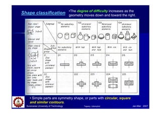
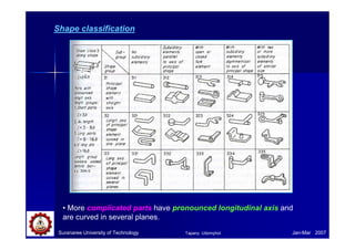
SlideShare a Scribd company logo
1 of 58
Download to read offline
Suranaree University of Technology Jan-Mar 2007
ForgingForging
• Introduction/objectives
• Classification of forging processes
- Hammer or drop forging
- Press forging
- Open-die forging
- Closed-die forging
• Calculation of forging loads
• Effect of forging on microstructure
• Residual stresses in forgings
• Typical forging defects
Chapter 2
Subjects of interest
Tapany Udomphol
ObjectivesObjectives
Suranaree University of Technology Jan-Mar 2007
• This chapter provides fundamental of metal working process for forging
in order to understand mathematical approaches used in the calculation
of applied forging loads required to cause plastic deformation to give the
final product.
• Classification of metal forging methods is also provided with
descriptions of defects observed from the forging processes.
• The solutions to tackle such defects will also be addressed.
Tapany Udomphol
IntroductionIntroduction
• Forging is the working of metal into a useful
shape by hammering or pressing.
• The oldest of the metalworking arts (primitive
blacksmith).
• Replacement of machinery occurred during
early the Industrial revolution.
• Forging machines are now capable of making
parts ranging in size of a bolt to a turbine
rotor.
• Most forging operations are carried out hot,
although certain metals may be cold-forged.
Suranaree University of Technology Jan-Mar 2007
www.eindiabusiness.com
www.prime-metals.com
Tapany Udomphol
Suranaree University of Technology Jan-Mar 2007
Forging operations
Edging is used to shape
the ends of the bars and to
gather metal. The metal
flow is confined in the
horizontal direction but it is
free to flow laterally to fill
the die. www.jsc-pfm.com
Drawing is used to reduce the cross-sectional area of
the workpiece with concurrent increase in length.
Piercing and punching are used to produce holes in
metals.
Tapany Udomphol
Suranaree University of Technology Jan-Mar 2007
Forging operations
Fullering is used to reduce the cross-sectional area
of a portion of the stock. The metal flow is outward
and away from the centre of the fuller.
i.e., forging of connecting rod for an internal-
combustion engine.
Fullers come
in different
shapes
• Fuller move fast and moves metal
perpendicular to the face
www.anvilfire.com
Fullers
Tapany Udomphol
Suranaree University of Technology Jan-Mar 2007
Forging operations
Swaging is used to produce a bar with a smaller
diameter (using concave dies).
Swaging at the ends, ready
for next forming process.
• Swaging provides a reduced round
cross section suitable for tapping,
threading, upsetting or other
subsequent forming and machining
operations.
• Swaging is a special type of forging
in which metal is formed by a
succession of rapid hammer blows
Tapany Udomphol
Suranaree University of Technology Jan-Mar 2007
Classification of forging processesClassification of forging processes
By equipment
1) Forging hammer or drop hammer
2) Press forging
By process
1) Open - die forging
2) Closed - die forging
Tapany Udomphol
Suranaree University of Technology Jan-Mar 2007
Forming machinesForming machines
There are four basic types of forging machines
Tapany Udomphol
Suranaree University of Technology Jan-Mar 2007
Hammer and press forging processes
Forging hammers
• Board hammer
• Power hammer
There are two basic types of forging
hammers used;
Forging presses
• Mechanical presses
• Hydraulic presses
There are two basic types of forging
presses available;
Tapany Udomphol
Suranaree University of Technology Jan-Mar 2007
Board hammer –forging hammer
Board hammer
• The upper die and ram are raised by
friction rolls gripping the board.
• After releasing the board, the ram falls
under gravity to produce the blow energy.
• The hammer can strike between 60-150
blows per minute depending on size and
capacity.
• The board hammer is an energy-
restricted machine. The blow energy
supplied equal the potential energy due
to the weight and the height of the fall.
• This energy will be delivered to the metal
workpiece to produce plastic
deformation.
Potential energy = mgh …Eq 1
Tapany Udomphol
Forging hammer or drop hammer
• Provide rapid impact blows to the surface of the metal.
• Dies are in two halves
- Lower : fixed to anvil
- Upper : moves up and down with the TUP.
• Energy (from a gravity drop) is adsorbed onto the metal,
in which the maximum impact is on the metal surface.
• Dies are expensive being accurately machined from
special alloys (susceptible to thermal shock).
• Drop forging is good for mass production of complex
shapes.
Suranaree University of Technology Jan-Mar 2007
TUP
Anvil
Drop hammer
Metal
Belt
Tapany Udomphol
Suranaree University of Technology Jan-Mar 2006
Example: Forging hammer or drop hammer
The energy supplied by
the blow is equal to the
potential energy due to
the weight of the ram and
the height of the fall.
Potential energy = mgh
Forging machine
…Eq 1
Tapany Udomphol
Suranaree University of Technology Jan-Mar 2007
Power hammer
Power hammer
• Power hammer provides greater
capacity, in which the ram is accelerated
on the downstroke by steam or air pressure
in addition to gravity.
• Steam or air pressure is also used to raise
the ram on the upstroke.
• The total energy supplied to the blow
in a power drop hammer is given by
HpAmgpAHmvW )(
2
1 2
+=+=
Where m = mass
v = velocity of ram at start of
deformation
g = acceleration of gravity
p = air or steam pressure
acting on ram cylinder on
downstroke
A = area of ram cylinder
H = height of the ram drop
…Eq 2
Tapany Udomphol
Suranaree University of Technology Jan-Mar 2007
Hydraulic press forging
• Using a hydraulic press or a mechanical
press to forge the metal, therefore, gives
continuous forming at a slower rate.
• Provide deeper penetration.
• Better properties (more homogeneous).
• Equipment is expensive.
Hydraulic press
Die
Die
Ram
High
pressure
fluid
Metal
Tapany Udomphol
Example: Hydraulic Press forging
• Hydraulic presses are load-
restricted machines in which
hydraulic pressure moves a piston
in a cylinder.
• The full press load is available at
any point during the full stroke of
the ram. Therefore, hydraulic
presses are ideally suited for
extrusion-type forging operation.
• Due to slow speed, contact time
is longer at the die-metal interface,
which causes problems such as
heat lost from workpiece and die
deterioration.
• Also provide close-tolerance forging.
Suranaree University of Technology Jan-Mar 2007
• Hydraulic presses are more
expensive than mechanical presses
and hammers.
Tapany Udomphol
Suranaree University of Technology Jan-Mar 2007
Mechanical press forging
Mechanical press
• Crank press translates rotary motion into
reciprocating linear motion of the press slide.
• The ram stroke is shorter than in a hammer or
hydraulic press.
• Presses are rated on the basis of the force
developed at the end of the stroke.
• The blow press is more like squeeze than
like the impact of the hammer, therefore, dies
can be less massive and die life is longer than
with a hammer.
• The total energy supplied during the stroke of
a press is given by
[ ]22
2
1
foIW ωω −=
Where I is moment of inertia of the flywheel
ωωωω is angular velocity, ωωωωo-original, ωωωωf-after deformation, rad.s-1
…Eq 3
Tapany Udomphol
Typical values of velocity for different
forging equipment
Forging machine Velocity range, ms-1
Gravity drop hammer 3.6-4.8
Power drop hammer 3.0-9.0
HERF machine 6.0-24.0
Mechanical press 0.06-1.5
Hydraulic press 0.06-0.30
Suranaree University of Technology Jan-Mar 2007
Remark: HERF – High Energy Rate Forging
Tapany Udomphol
Closed and open die forging processes
Open-die forging
Closed-die forging
Impression-die
forging
Suranaree University of Technology Jan-Mar 2007Tapany Udomphol
Suranaree University of Technology Jan-Mar 2007
Open-die forging
• Open-die forging is carried
out between flat dies or dies of
very simple shape.
• The process is used for
mostly large objects or when
the number of parts produced
is small.
• Open-die forging is often used
to preform the workpiece for
closed-die forging.
Tapany Udomphol
Suranaree University of Technology Jan-Mar 2007
Closed-die forging (or impression-die forging)
• The workpiece is deformed between two
die halves which carry the impressions
of the desired final shape.
• The workpiece is deformed under high
pressure in a closed cavity.
• The process provide precision forging
with close dimensional tolerance.
• Closed dies are expensive.
• Normally used for smaller components.
Tapany Udomphol
Suranaree University of Technology Jan-Mar 2007
Closed-die forging operation
Forgingload
Forgingcomplete
Forging stroke
Die cavity
completely
filled
Flash begins
to form
Dies contact
workpiece
Typical curve of forging load vs. stroke for
closed-die forging.
Preshaped Rough-forge Finishing die Trimming die Final
product
billet
Flash is the excess metal, which
squirts out of the cavity as a thick
ribbon of metal.
Tapany Udomphol
Suranaree University of Technology Jan-Mar 2007
The flash serves two purposes:
• Acts as a ‘safety value’ for excess metal.
• Builds up high pressure to ensure that
the metal fills all recesses of the die cavity.
Functions of flash
Remark: It is necessary to achieve complete filling of the forging cavity
without generating excessive pressures against the die that may
cause it to fracture.
Tapany Udomphol
Suranaree University of Technology Jan-Mar 2007
Example: Die set and forging steps for the
manufacturing of an automobile engine connecting rod
• Preforming of a round piece in an open die
arrangement.
• Rough shape is formed using a block die.
• The finishing die is used to bring the part to
final tolerances and surface finish.
• Removal of flash (excess metal).
Steering knuckle FlangeRail
http://www.hirschvogel.de/en/produkti
onsverfahren/warmumformung.php
See simulation
Tapany Udomphol
Closed-die design
Usually the deformation in closed-die forging is very complex and the
design of the intermediate steps to make a final precision part requires
considerable experience and skill.
The design of a part for production by closed-die forging involves
the prediction of
• workpiece volume and weight
• number of preforming steps and their configuration
• flash dimensions in preforming and finishing dies
the load and energy requirement for each forging operation, for
example; the flow stress of the materials, the fictional condition,
the flow of the material in order to develop the optimum geometry for
the dies.
Suranaree University of Technology Jan-Mar 2007Tapany Udomphol
Suranaree University of Technology Jan-Mar 2007
Shape classification •The degree of difficulty increases as the
geometry moves down and toward the right.
• Simple parts are symmetry shape, or parts with circular, square
and similar contours.
Tapany Udomphol
Suranaree University of Technology Jan-Mar 2007
Shape classification
• More complicated parts have pronounced longitudinal axis and
are curved in several planes.
Tapany Udomphol
Suranaree University of Technology Jan-Mar 2007
Preform design is the most difficult and
critical step in forging design. Proper
preform design assures defect-free flow,
complete die fill, and minimum flash loss.
- Metal flow consists only of two basic types
• extrusion (flow parallel to the direction of
the die motion)
• upsetting ( flow perpendicular to the
direction of the die motion).
- However both types of metal flow occur
simultaneously.
- We need to identify the neutral surface
since metal flows away from the neutral
surface in a direction perpendicular to the
die motion.
mfge.atilim.edu.tr/
Metal flow during forging
Upsetting
http://www.qform3d.com/images/el
ectrups/elecrups2.gif
See simulation
Tapany Udomphol
Suranaree University of Technology Jan-Mar 2007
Metal flow in forging
Finite element analysis of upsetting an aluminium cylinder
• It is a numerical modelling technique that involves splitting the whole of
a body into a series of simple geometrical elements that are joined
together at points (nodes) where both equilibrium (lower bound) and
compatibility (upper bound) requirement are established.
• Finite element analysis
was originally developed to
model the elastic
deformation of complex
structures but recently has
been extended to cover large
plastic deformation under real
stress system.
Tapany Udomphol
Suranaree University of Technology Jan-Mar 2007
General considerations for preform design
• Area of each cross section = area in the finished cross section + flash.
• Concave radii of the preform > radii on the final forging part.
• Cross section of the preform should be higher and narrower than the
final cross section, so as to accentuate upsetting flow and minimise
extrusion flow.
• Shape with thin and long
sections or projections (ribs and
webs) are more difficult to
process because they have
higher surface area per unit
volume increasing friction and
temperature effects.
draft angle
web
rib
Some typical nomenclature
Tapany Udomphol
Suranaree University of Technology Jan-Mar 2007
General rules of closed-die design
• The die set should be designed for smooth metal flow – symmetry
dies (spherical or blocklike) are the easier than thin and long section.
• Shape changes in section are to be avoided.
• Dies should be designed for the minimum flash to do the job.
• Generous fillet dimensions should be allowed, therefore, forging dies
must be tapered or drafted to facilitate removal of the finished piece.
• Draft allowance is approximately 3-5o outside and 7-10o inside.
• Dies with inclined angles should have counterlock to prevent the dies
from sliding apart from each other due to side thrust.
Counterlock
Side thrust
draft angle
web
rib
Tapany Udomphol
Die materials
• Thermal shock resistance
• Thermal fatigue resistance
• High temperature strength
• High wear resistance
• Hgh toughness and ductility
• High hardenability
• High dimensional stability during hardening
• High machinability
Required properties
Die materials: alloyed steels (with Cr,
Mo, W, V), tool steels, cast steels or cast
iron. (Heat treatments such are nitriding
or chromium plating are required to
improve die life)
Suranaree University of Technology Jan-Mar 2007
Forging die
www.nitrex.com
1) Carbon steels with 0.7-0.85% C are appropriate for small tools and
flat impressions.
2) Medium-alloyed tool steels for hammer dies.
3) Highly alloyed steels for high temperature resistant dies used in
presses and horizontal forging machines.
Note:
Tapany Udomphol
Die materials
Suranaree University of Technology Jan-Mar 2007
Common steels used for forging dies
H12H12X37CrMoW51X37CrMoW51
--X30WCrV53X30WCrV53--X30WCrV52X30WCrV52--X30WCrV53X30WCrV53
H10H10X32CrMoV33X32CrMoV33H10H10X32CrMoV33X32CrMoV33H10H10X32CrMoV33X32CrMoV33
H11H11X38CrMoV51X38CrMoV51H21H21X30WCrV93X30WCrV93H11H11X38CrMoV51X38CrMoV51
--35NiCrMo1635NiCrMo16
6F36F357NiCrMoV7757NiCrMoV77--57NiCrMoV7757NiCrMoV77--57NiCrMoV7757NiCrMoV77
6F26F256NiCrMoV756NiCrMoV76F36F356NiCrMoV756NiCrMoV7
55NiCrMoV655NiCrMoV66F26F255NiCrMoV655NiCrMoV6Die insertsDie inserts
H10H10X32CrMoV33X32CrMoV33
H11H11X38CrMoV51X38CrMoV51H11H11X38CrMoV51X38CrMoV51--40CrMnMo740CrMnMo7
--X30WCrV53X30WCrV53H21H21X30WCrV53X30WCrV53--60MnSi460MnSi4
--C85 W2C85 W2
--C70 W2C70 W2Forging diesForging dies
AISIAISIDINDINAISIAISIDINDINAISIAISIDINDIN
Light alloysLight alloysCopper and copper alloysCopper and copper alloysSteelsSteelsForgingForging
materialsmaterials
Tapany Udomphol
Die materials
Ultra hard surface coatings
Ultra hard surface coating
on die surface is used to
• Improve die life.
• Reduce energy input.
• Reduce die-related uptime
and downtime.
• Reduce particulate emission
from lubricants.
Suranaree University of Technology Jan-Mar 2007
Die life can be increased by
1) Improving die materials such as using composite die or
2) Using surface coating or self-lubricating coatings
Current forging Future forging
Innovative
die
m
aterials
Innovative
surface
m
odification
http://www.eere.energy.gov/industry/supporting_industries
/pdfs/innovative_die_materials.pdf
Tapany Udomphol
Die failures
Suranaree University of Technology Jan-Mar 2007
Different types of die failure
Wear (abrasion)
Thermal fatigue
Mechanical fatigue
Permanent deformation
• Different parts of dies are liable to permanent deformation and wear
resulting from mechanical and thermal fatigue.
• Important factors: shape of the forging, die materials, how the
workpiece is heated, coating of die surface, the operating temperature
(should not exceed the annealing temperature).
Tapany Udomphol
Calculation of forging loads
Suranaree University of Technology Jan-Mar 2007
The calculation for forging load can be divided into three cases according to friction:
• In the absence of friction
• Low friction condition (lower bound analysis or sliding condition)
• High friction condition (sticky friction condition)
Utotal = Uideal + Ufriction + Uredundant
The total energy required for deformation process;
Note: redundant work = work that does not contribute to
shape change of the workpiece
Efficiency of a given deformation process ηηηη is
total
ideal
U
U
=η
Note: ηηηη = 0.3-0.6 for extrusion
= 0.75-0.95 for rolling
= 0.10-0.20 for closed die forging
Tapany Udomphol
1) In the absence of friction
By assuming that there is no friction at die-workpiece interface, the forging
load is therefore the compressive force (P) acting on a round metal bar.
AP oσ=
Where P is the compressive force
σσσσo is the yield stress of the metal
A is the cross sectional area of the metal.
And the compressive stress (p) produced by this force P can be
obtained from
oo
o
oo hD
Ah
hD
Ph
D
Ph
p 222
444
π
σ
ππ
=→=
Suranaree University of Technology Jan-Mar 2007
Where h is the instantaneous height of the metal bar during forging
ho is the original height of the metal bar
Do is the original diameter of the metal bar.
Then ….Eq. 4
….Eq. 5
Do
ho
D
h
Note: from volume constanthDhDo
22
=
Tapany Udomphol
Suranaree University of Technology Jan-Mar 2007
We have engineering strain in compression,
o
o
o h
hh
h
h
e
−
=
∆
=
And true strain in compression,
h
h
h
h
h
dh o
o
h
ho
lnln −=== ∫ε
The relationship between e and εεεε is
( )1ln += eε
….Eq. 6
….Eq. 7
….Eq. 8
Do
ho
D
h
Tapany Udomphol
2) Low friction condition (Lower bound analysis)
By considering the equilibrium of forces acting on the workpiece at any
instant of deformation.
• For example, if we consider the effect of friction
on an upset forging operation in plane strain
condition (rigid-plastic behaviour, see Fig).
• To calculate the total forming load, we have
to determine the local stresses needed to
deform each element of a workpiece of height h
and width 2a.
• In plane strain condition, as the workpiece is
reduced in height, it expands laterally and all
deformation is confined in the x-y plane. This
lateral expansion causes frictional forces to act
in opposition to the movement.
• Assuming that there is no redundant work
and the material exhibits rigid-plastic
behaviour, and all stress on the body are
compressive.
Suranaree University of Technology Jan-Mar 2007Tapany Udomphol
Suranaree University of Technology Jan-Mar 2007
• Consider the force acting on a vertical element of
unit length and width dx. The element is at some
distance x from the central ‘no-slip’ point, in this
case to the right.
• The vertical force acting on the element is
dxareastress yσ=×
• If the coefficient of friction for the die-workpiece
interface is µµµµ, the magnitude of the friction force
will be µσµσµσµσydx. The frictional force acts at both
ends of the element so the total horizontal force
from the right is 2µσµσµσµσydx.
• Acting on the left will be the force σσσσxh and from the right the force (σσσσx+dσσσσx)h.
The horizontal compressive stress σσσσx varies from a maximum at the centre of
the workpiece to zero at the edge and changes by dσσσσx across the element
width dx.
….Eq. 9
Tapany Udomphol
Suranaree University of Technology Jan-Mar 2007
Balancing the horizontal forces acting on
the element:
( ) xyxx hdxdh σµσσσ =++ 2 ….Eq. 10
Rearranging, we have
xy hddx σµσ −=2 ….Eq. 11
and therefore
dx
h
d
y
x µ
σ
σ 2
−= ….Eq. 12
Tapany Udomphol
Suranaree University of Technology Jan-Mar 2007
As the frictional force µσµσµσµσy is usually much smaller than
both σσσσx and σσσσy , which are principal stresses. Thus
we can use them in the yield criterion when the slab
will yield
'
3
2
ooxy σσσσ ==−
Where σσσσ ‘
o is the yield stress in plane strain.
….Eq. 13
Differentiation of the yield condition gives dσσσσy = dσσσσx ,
and substituting for dσσσσx in Eq. 12 gives
dx
h
d
y
y µ
σ
σ 2
−=
Integrating both sides of this differential equation gives
….Eq. 14
oy C
h
x
+−=
µ
σ
2
ln ….Eq. 15 or 





−=
h
x
Cy
µ
σ
2
exp ….Eq. 16
where Co is a constant of integration.
Tapany Udomphol
Suranaree University of Technology Jan-Mar 2007
We can evaluate C by looking at the boundary conditions. At the edge of the
workpiece where x = a, σσσσx = 0 and from the yield criterion σσσσy - σσσσx = σσσσ‘
o, so
σσσσy = σσσσ‘
o and therefore:
'2
exp o
h
a
C σ
µ
=





−
so






=
h
a
C o
µ
σ
2
exp'
….Eq. 17
….Eq. 18
Using this in Eq.16, we find
( )





−= xa
h
oy
µ
σσ
2
exp'
….Eq. 19
X
σo
Xa-a
σσσσ‘o
σσσσy






h
a
o
µ
σ
2
exp'
( )



− xa
h
o
µ
σ
2
exp'
Friction hill
x = ax = 0x = -a
Tapany Udomphol
Suranaree University of Technology Jan-Mar 2007
The total forging load, P, is given by awpP
_
2=
Where p is the average forming pressure across the workpiece
w is the width of the workpiece (in the plane of the paper).
….Eq. 20
This equals σσσσy and can be estimated by integrating Eq.19:
( ) dxxa
ha
dx
a
p
a
o
o
a
o
y
∫∫ 





−==
− µσσ 2
exp
'
….Eq. 21
The integration in Eq. 18 can be simplified if we make the following
approximation to Eq. 16. The general series expansion for exp x is
...
!3!2
1exp
32
++++=
xx
xx ….Eq. 22
Since µµµµ is usually small (<1) we can approximate exp x as (1+x) for small x.
Tapany Udomphol
Suranaree University of Technology Jan-Mar 2007
Thus we can approximate Eq.19 as
( )





 −
+=
h
xa
oy
µ
σσ
2
1'
and Eq.21 becomes
( ) dx
h
xa
a
p
a
o
∫ 




 −
+=
0
'_
2
1
µσ
….Eq. 23
….Eq. 24
Integrating this gives:
a
o
h
x
h
ax
x
a
p
0
2'_
2






−+=
µµσ ….Eq. 25
So that the average axial tooling pressure, p, is






+=
h
a
p o
µ
σ 1'
_
….Eq. 26
We can see that as the ratio a/h increases, the forming pressure p and
hence the forming load rises rapidly.
Tapany Udomphol
Suranaree University of Technology Jan-Mar 2007
Example:
The flash has high deformation resistance than in the die (due to
much higher a/h ratio), therefore the material completely fills the
cavity rather than being extruded sideward out of the die.
Tapany Udomphol
In the situation where the friction force is high, the stress acting on the
metal is
3) High friction condition (sticky friction)






+= 1
2
'
_
h
a
p oσ
….Eq. 27
Under these conditions, the forming load is dependent on the flow stress
of the material and the geometry of the workpiece.
For example: if the a/h ratio is high, say a/h = 8, then p = 5σσσσ’
o. The local
stress on the tooling can therefore be very high indeed and 5σσσσ’
o is probably
high enough to deform the tooling in most cold forming operation.
Suranaree University of Technology Jan-Mar 2007
Solutions:
• reducing µµµµ to ensure that sticking friction conditions do not apply.
• changing the workpiece geometry.
• reducing σσσσ’
o by increasing the temperature.






−
−
= 1'
h
xa
oy σσ
and the mean forging pressure is
….Eq. 28
Tapany Udomphol
Suranaree University of Technology Jan-Mar 2007
dx
h
d
y
y µ
σ
σ 2
−= ….Eq. 14
In the case of sticky friction, if we replace the force µσµσµσµσy with k (the average
shear stress of the material) in Eq.14
then we have
h
dx
h
dx
dx
h
k
d o
o
y
'
_
3
22
σ
σ
σ −=−=−= ….Eq. 29
Integrating
C
h
x
oy +−= '
σσ ….Eq. 30
Since σσσσy = σσσσ’
o at x = a,
then
h
a
C oo
''
σσ += ….Eq. 31
Replacing C in Eq. 30 we then have






+
−
=++−= 1''''
h
xa
h
a
h
x
ooooy σσσσσ Or Eq. 27
Tapany Udomphol
Example:
A block of lead 25x25x150 mm3 is pressed between flat dies to a size
6.25x100x150 mm3. If the uniaxial flow stress σσσσo = 6.9 MPa and µµµµ = 0.25,
determine the pressure distribution over the 100 mm dimension (at x = 0, 25
and 50 mm and the total forging load in the sticky friction condition.
Dieter, page 574-575
Since 150 mm dimension does not change, the deformation is plane strain.
From Eq.19.
( )





−= xa
h
oy
µ
σσ
2
exp
3
2
At the centreline of the slab (x = 0)
( ) MPa435050
25.6
)25.0(2
exp
3
)9.6(2
max =



−=σ
Likewise, at 25 and 50 mm, the stress distribution will be 58.9 and 8.0 MPa
respectively.
Suranaree University of Technology Jan-Mar 2007
oo σσ
3
2'
=where
Tapany Udomphol
Suranaree University of Technology Jan-Mar 2007
The mean forging load (in the sticky friction condition) from Eq.28 is






+= 1
23
2_
h
a
p oσ
MPap 8.391
5.12
50
3
)9.6(2_
=





+=
We calculate the forging load on the assumption that the stress distribution
is based on 100 percent sticky friction. Then
The forging load is P = stress x area
= (39.8x10⁶)(100x10-3)(150x10-3)
= 597 kN
= 61 tonnes.
Tapany Udomphol
Suranaree University of Technology Jan-Mar 2007
Effect of forging on microstructure
grain structure resulting from (a) forging, (b) machining and (c) casting.
• The formation of a grain structure in forged parts is elongated in the
direction of the deformation.
• The metal flow during forging provides fibrous microstructure (revealed by
etching). This structure gives better mechanical properties in the plane of
maximum strain but (perhaps) lower across the thickness.
• The workpiece often undergo recrystallisation, therefore, provide finer
grains compared to the cast dendritic structure resulting in improved
mechanical properties.
Tapany Udomphol
Suranaree University of Technology Jan-Mar 2007
Forming textures
Redistribution of metal structures occurring during forming
process involves two principle components; 1) redistribution of
inclusions and 2) crystallographic orientation of the grains
1) The redistribution of inclusions
Redistribution
during forming of
(a) soft inclusions
(b) hard inclusions
Tapany Udomphol
Suranaree University of Technology Jan-Mar 2007
Forming textures
2) Crystallographic orientation of the grains
Castings Forgings
Mainly epitaxial,
dendritic or
equiaxed grains
Redistribution of grains
in the working directions
Fibre structure in forged steels
Cast iron structure
Tapany Udomphol
Residual stresses in forging
• The residual stress produced in forgings as a results of
inhomogeneous deformation are generally small because the
deformation is normally carried out well into the hot-working region.
• However, appreciable residual stresses and warping can occur on
the quenching of steel forgings in heat treatment.
• Large forgings are subjected to the formation of small cracks, or
flakes at the centre of the cross section. This is associated with the high
hydrogen content usually present in steel ingots of large size, coupled
with the presence of residual stresses.
• Finite element analysis is used to predict residual stresses in forgings.
• Large forgings therefore have to be slowly cooled from the working
temperature. Examples: burying the forging in ashes for a period of time or
using a controlled cooling furnace.
Suranaree University of Technology Jan-Mar 2007Tapany Udomphol
Suranaree University of Technology Jan-Mar 2007
Typical forging defects
• Incomplete die filling.
• Die misalignment.
• Forging laps.
• Incomplete forging penetration- should
forge on the press.
• Microstructural differences resulting in
pronounced property variation.
• Hot shortness, due to high sulphur
concentration in steel and nickel.
Fluorescence penetrant
reveals Forging laps
files.bnpmedia.com
See simulation
www.komatsusanki.co.jp
Tapany Udomphol
Suranaree University of Technology Jan-Mar 2007
Typical forging defects
• Pitted surface, due to oxide scales occurring
at high temperature stick
on the dies.
• Buckling, in upsetting forging. Subject to
high compressive stress.
• Surface cracking, due to temperature
differential between surface and
centre, or excessive working of the surface
at too low temperature.
• Microcracking, due to residual stress.
www.mece.ualberta.ca
Buckling
http://upload.wikimedia.org
Tapany Udomphol
Typical forging defects
Suranaree University of Technology Jan-Mar 2007
Cracking at the flash Cold shut or fold
Internal cracking
• Flash line crack, after trimming-occurs more often in thin
workpieces. Therefore should increase the thickness of the flash.
• Cold shut or fold , due to flash or fin from prior forging steps is
forced into the workpiece.
• Internal cracking, due to secondary tensile stress.
Tapany Udomphol
Suranaree University of Technology Jan-Mar 2007
Summary
• Mainly hot forging – Blacksmith, now using water power, steam,
electricity, hydraulic machines.
• Heavy forging
- Hydraulic press = slow, high force squeeze.
- Pieces up to 200 tonnes with forces up to 25,000 tonnes.
- Simple tools squeeze metal into shape (open-die forging).
- Sufficient deformation must be given to break up the ‘as cast’
structure.
- Reheating is often needed to maintain sufficient temperature
for hot working.
- Forging is costly but eliminates some as-cast defects
- Continuous ‘grain flow’ in the direction of metal flow is
revealed by etching.
- Impurities (inclusions and segregation) have become
elongated and (unlike casting) gives superior properties in the
direction of elongation.
Tapany Udomphol
Suranaree University of Technology Jan-Mar 2007
References
• Dieter, G.E., Mechanical metallurgy, 1988, SI metric edition,
McGraw-Hill, ISBN 0-07-100406-8.
• Edwards, L. and Endean, M., Manufacturing with materials,
1990, Butterworth Heinemann, ISBN 0-7506-2754-9.
• Beddoes, J. and Bibbly M.J., Principles of metal manufacturing
process, 1999, Arnold, ISBN 0-470-35241-8.
• Lange, K., Handbook of metal forming, 1919, McGraw-Hill Book
company, ISBN 0-07-036285-8.
• Lecture note, Sheffield University, 2003.
• Metal forming processes, Prof Manus.
Tapany Udomphol

More Related Content

What's hot (20)

Metal forming processes full
Metal forming processes fullMetal forming processes full
Metal forming processes full
 
Forging
ForgingForging
Forging
 
Fundamentals of metal forming processes
Fundamentals of metal forming processesFundamentals of metal forming processes
Fundamentals of metal forming processes
 
Sheet Metal Forming
Sheet Metal FormingSheet Metal Forming
Sheet Metal Forming
 
Forging
ForgingForging
Forging
 
Forging
ForgingForging
Forging
 
Metal forming process
Metal forming processMetal forming process
Metal forming process
 
Design of gating systems
Design of gating systemsDesign of gating systems
Design of gating systems
 
Sheet metal processes
Sheet metal processesSheet metal processes
Sheet metal processes
 
Centrifugal casting 1
Centrifugal casting 1Centrifugal casting 1
Centrifugal casting 1
 
06 sheet metal forming
06 sheet metal forming06 sheet metal forming
06 sheet metal forming
 
ORBITAL FORGING
ORBITAL FORGINGORBITAL FORGING
ORBITAL FORGING
 
Stretch forming
Stretch formingStretch forming
Stretch forming
 
Rolling Process
Rolling ProcessRolling Process
Rolling Process
 
Die casting
Die castingDie casting
Die casting
 
Extrusion of metals by Hariprasad
Extrusion of metals by HariprasadExtrusion of metals by Hariprasad
Extrusion of metals by Hariprasad
 
Sheet Metal Forming
Sheet Metal FormingSheet Metal Forming
Sheet Metal Forming
 
ppt on Sheet metal process
ppt on Sheet metal processppt on Sheet metal process
ppt on Sheet metal process
 
Resistance welding
Resistance weldingResistance welding
Resistance welding
 
Deep drawing
Deep drawingDeep drawing
Deep drawing
 

Similar to forging

Similar to forging (20)

02_Forging.pdf
02_Forging.pdf02_Forging.pdf
02_Forging.pdf
 
Extrusion Processes
Extrusion ProcessesExtrusion Processes
Extrusion Processes
 
06_Sheet-metal forming (2).pptx
06_Sheet-metal forming (2).pptx06_Sheet-metal forming (2).pptx
06_Sheet-metal forming (2).pptx
 
06_Sheet-metal forming.pptx
06_Sheet-metal forming.pptx06_Sheet-metal forming.pptx
06_Sheet-metal forming.pptx
 
UNIT3-Special casting processmechanica.ppt
UNIT3-Special casting processmechanica.pptUNIT3-Special casting processmechanica.ppt
UNIT3-Special casting processmechanica.ppt
 
Study of forging , its classification & types
Study of forging , its classification & typesStudy of forging , its classification & types
Study of forging , its classification & types
 
Metal-forming-Unit-2.1.pdf
Metal-forming-Unit-2.1.pdfMetal-forming-Unit-2.1.pdf
Metal-forming-Unit-2.1.pdf
 
Forging final
Forging finalForging final
Forging final
 
Forging
ForgingForging
Forging
 
Different Types of Production Processes
Different Types of Production ProcessesDifferent Types of Production Processes
Different Types of Production Processes
 
Unconventional forming
Unconventional formingUnconventional forming
Unconventional forming
 
Rotary forging OR Orbital forging
Rotary forging OR Orbital forgingRotary forging OR Orbital forging
Rotary forging OR Orbital forging
 
Group4
Group4Group4
Group4
 
MANUFACTURING TECHNOLOGY-I UNIT 3
MANUFACTURING TECHNOLOGY-I UNIT 3MANUFACTURING TECHNOLOGY-I UNIT 3
MANUFACTURING TECHNOLOGY-I UNIT 3
 
UNIT - III.ppt
UNIT - III.pptUNIT - III.ppt
UNIT - III.ppt
 
MANUFACTURING PROCESS-I
MANUFACTURING PROCESS-IMANUFACTURING PROCESS-I
MANUFACTURING PROCESS-I
 
Forging ppt
Forging pptForging ppt
Forging ppt
 
Metal Forging
Metal ForgingMetal Forging
Metal Forging
 
Deep drawing
Deep drawingDeep drawing
Deep drawing
 
Forging.pptx
Forging.pptxForging.pptx
Forging.pptx
 

More from Ilyas Hussain

Advanced Characterization Technique - SEM
Advanced Characterization Technique - SEMAdvanced Characterization Technique - SEM
Advanced Characterization Technique - SEMIlyas Hussain
 
Metallurgical structures
Metallurgical structuresMetallurgical structures
Metallurgical structuresIlyas Hussain
 
Aluminium alloy a201
Aluminium alloy   a201Aluminium alloy   a201
Aluminium alloy a201Ilyas Hussain
 
Assignment parts feeder
Assignment parts feederAssignment parts feeder
Assignment parts feederIlyas Hussain
 
Force measurement in grinding using dynamometer
Force measurement in grinding  using dynamometerForce measurement in grinding  using dynamometer
Force measurement in grinding using dynamometerIlyas Hussain
 
Thixocasting or semi solid metal casting
Thixocasting or semi solid metal castingThixocasting or semi solid metal casting
Thixocasting or semi solid metal castingIlyas Hussain
 
Atomic hyrogen arc welding
Atomic hyrogen arc weldingAtomic hyrogen arc welding
Atomic hyrogen arc weldingIlyas Hussain
 

More from Ilyas Hussain (11)

Advanced Characterization Technique - SEM
Advanced Characterization Technique - SEMAdvanced Characterization Technique - SEM
Advanced Characterization Technique - SEM
 
Parts feeder
Parts feederParts feeder
Parts feeder
 
Components of die
Components of dieComponents of die
Components of die
 
Metallurgical structures
Metallurgical structuresMetallurgical structures
Metallurgical structures
 
Aluminium alloy a201
Aluminium alloy   a201Aluminium alloy   a201
Aluminium alloy a201
 
Assignment parts feeder
Assignment parts feederAssignment parts feeder
Assignment parts feeder
 
Force measurement in grinding using dynamometer
Force measurement in grinding  using dynamometerForce measurement in grinding  using dynamometer
Force measurement in grinding using dynamometer
 
Comparators ppt
Comparators pptComparators ppt
Comparators ppt
 
Lean in fishing net
Lean in fishing netLean in fishing net
Lean in fishing net
 
Thixocasting or semi solid metal casting
Thixocasting or semi solid metal castingThixocasting or semi solid metal casting
Thixocasting or semi solid metal casting
 
Atomic hyrogen arc welding
Atomic hyrogen arc weldingAtomic hyrogen arc welding
Atomic hyrogen arc welding
 

Recently uploaded

chaitra-1.pptx fake news detection using machine learning
chaitra-1.pptx  fake news detection using machine learningchaitra-1.pptx  fake news detection using machine learning
chaitra-1.pptx fake news detection using machine learningmisbanausheenparvam
 
main PPT.pptx of girls hostel security using rfid
main PPT.pptx of girls hostel security using rfidmain PPT.pptx of girls hostel security using rfid
main PPT.pptx of girls hostel security using rfidNikhilNagaraju
 
OSVC_Meta-Data based Simulation Automation to overcome Verification Challenge...
OSVC_Meta-Data based Simulation Automation to overcome Verification Challenge...OSVC_Meta-Data based Simulation Automation to overcome Verification Challenge...
OSVC_Meta-Data based Simulation Automation to overcome Verification Challenge...Soham Mondal
 
Sachpazis Costas: Geotechnical Engineering: A student's Perspective Introduction
Sachpazis Costas: Geotechnical Engineering: A student's Perspective IntroductionSachpazis Costas: Geotechnical Engineering: A student's Perspective Introduction
Sachpazis Costas: Geotechnical Engineering: A student's Perspective IntroductionDr.Costas Sachpazis
 
Past, Present and Future of Generative AI
Past, Present and Future of Generative AIPast, Present and Future of Generative AI
Past, Present and Future of Generative AIabhishek36461
 
VICTOR MAESTRE RAMIREZ - Planetary Defender on NASA's Double Asteroid Redirec...
VICTOR MAESTRE RAMIREZ - Planetary Defender on NASA's Double Asteroid Redirec...VICTOR MAESTRE RAMIREZ - Planetary Defender on NASA's Double Asteroid Redirec...
VICTOR MAESTRE RAMIREZ - Planetary Defender on NASA's Double Asteroid Redirec...VICTOR MAESTRE RAMIREZ
 
Artificial-Intelligence-in-Electronics (K).pptx
Artificial-Intelligence-in-Electronics (K).pptxArtificial-Intelligence-in-Electronics (K).pptx
Artificial-Intelligence-in-Electronics (K).pptxbritheesh05
 
power system scada applications and uses
power system scada applications and usespower system scada applications and uses
power system scada applications and usesDevarapalliHaritha
 
APPLICATIONS-AC/DC DRIVES-OPERATING CHARACTERISTICS
APPLICATIONS-AC/DC DRIVES-OPERATING CHARACTERISTICSAPPLICATIONS-AC/DC DRIVES-OPERATING CHARACTERISTICS
APPLICATIONS-AC/DC DRIVES-OPERATING CHARACTERISTICSKurinjimalarL3
 
complete construction, environmental and economics information of biomass com...
complete construction, environmental and economics information of biomass com...complete construction, environmental and economics information of biomass com...
complete construction, environmental and economics information of biomass com...asadnawaz62
 
INFLUENCE OF NANOSILICA ON THE PROPERTIES OF CONCRETE
INFLUENCE OF NANOSILICA ON THE PROPERTIES OF CONCRETEINFLUENCE OF NANOSILICA ON THE PROPERTIES OF CONCRETE
INFLUENCE OF NANOSILICA ON THE PROPERTIES OF CONCRETEroselinkalist12
 
HARMONY IN THE NATURE AND EXISTENCE - Unit-IV
HARMONY IN THE NATURE AND EXISTENCE - Unit-IVHARMONY IN THE NATURE AND EXISTENCE - Unit-IV
HARMONY IN THE NATURE AND EXISTENCE - Unit-IVRajaP95
 
Application of Residue Theorem to evaluate real integrations.pptx
Application of Residue Theorem to evaluate real integrations.pptxApplication of Residue Theorem to evaluate real integrations.pptx
Application of Residue Theorem to evaluate real integrations.pptx959SahilShah
 
Gfe Mayur Vihar Call Girls Service WhatsApp -> 9999965857 Available 24x7 ^ De...
Gfe Mayur Vihar Call Girls Service WhatsApp -> 9999965857 Available 24x7 ^ De...Gfe Mayur Vihar Call Girls Service WhatsApp -> 9999965857 Available 24x7 ^ De...
Gfe Mayur Vihar Call Girls Service WhatsApp -> 9999965857 Available 24x7 ^ De...srsj9000
 
Decoding Kotlin - Your guide to solving the mysterious in Kotlin.pptx
Decoding Kotlin - Your guide to solving the mysterious in Kotlin.pptxDecoding Kotlin - Your guide to solving the mysterious in Kotlin.pptx
Decoding Kotlin - Your guide to solving the mysterious in Kotlin.pptxJoão Esperancinha
 
Study on Air-Water & Water-Water Heat Exchange in a Finned Tube Exchanger
Study on Air-Water & Water-Water Heat Exchange in a Finned Tube ExchangerStudy on Air-Water & Water-Water Heat Exchange in a Finned Tube Exchanger
Study on Air-Water & Water-Water Heat Exchange in a Finned Tube ExchangerAnamika Sarkar
 
Call Us ≽ 8377877756 ≼ Call Girls In Shastri Nagar (Delhi)
Call Us ≽ 8377877756 ≼ Call Girls In Shastri Nagar (Delhi)Call Us ≽ 8377877756 ≼ Call Girls In Shastri Nagar (Delhi)
Call Us ≽ 8377877756 ≼ Call Girls In Shastri Nagar (Delhi)dollysharma2066
 

Recently uploaded (20)

9953056974 Call Girls In South Ex, Escorts (Delhi) NCR.pdf
9953056974 Call Girls In South Ex, Escorts (Delhi) NCR.pdf9953056974 Call Girls In South Ex, Escorts (Delhi) NCR.pdf
9953056974 Call Girls In South Ex, Escorts (Delhi) NCR.pdf
 
chaitra-1.pptx fake news detection using machine learning
chaitra-1.pptx  fake news detection using machine learningchaitra-1.pptx  fake news detection using machine learning
chaitra-1.pptx fake news detection using machine learning
 
main PPT.pptx of girls hostel security using rfid
main PPT.pptx of girls hostel security using rfidmain PPT.pptx of girls hostel security using rfid
main PPT.pptx of girls hostel security using rfid
 
★ CALL US 9953330565 ( HOT Young Call Girls In Badarpur delhi NCR
★ CALL US 9953330565 ( HOT Young Call Girls In Badarpur delhi NCR★ CALL US 9953330565 ( HOT Young Call Girls In Badarpur delhi NCR
★ CALL US 9953330565 ( HOT Young Call Girls In Badarpur delhi NCR
 
OSVC_Meta-Data based Simulation Automation to overcome Verification Challenge...
OSVC_Meta-Data based Simulation Automation to overcome Verification Challenge...OSVC_Meta-Data based Simulation Automation to overcome Verification Challenge...
OSVC_Meta-Data based Simulation Automation to overcome Verification Challenge...
 
Sachpazis Costas: Geotechnical Engineering: A student's Perspective Introduction
Sachpazis Costas: Geotechnical Engineering: A student's Perspective IntroductionSachpazis Costas: Geotechnical Engineering: A student's Perspective Introduction
Sachpazis Costas: Geotechnical Engineering: A student's Perspective Introduction
 
young call girls in Green Park🔝 9953056974 🔝 escort Service
young call girls in Green Park🔝 9953056974 🔝 escort Serviceyoung call girls in Green Park🔝 9953056974 🔝 escort Service
young call girls in Green Park🔝 9953056974 🔝 escort Service
 
Past, Present and Future of Generative AI
Past, Present and Future of Generative AIPast, Present and Future of Generative AI
Past, Present and Future of Generative AI
 
VICTOR MAESTRE RAMIREZ - Planetary Defender on NASA's Double Asteroid Redirec...
VICTOR MAESTRE RAMIREZ - Planetary Defender on NASA's Double Asteroid Redirec...VICTOR MAESTRE RAMIREZ - Planetary Defender on NASA's Double Asteroid Redirec...
VICTOR MAESTRE RAMIREZ - Planetary Defender on NASA's Double Asteroid Redirec...
 
Artificial-Intelligence-in-Electronics (K).pptx
Artificial-Intelligence-in-Electronics (K).pptxArtificial-Intelligence-in-Electronics (K).pptx
Artificial-Intelligence-in-Electronics (K).pptx
 
power system scada applications and uses
power system scada applications and usespower system scada applications and uses
power system scada applications and uses
 
APPLICATIONS-AC/DC DRIVES-OPERATING CHARACTERISTICS
APPLICATIONS-AC/DC DRIVES-OPERATING CHARACTERISTICSAPPLICATIONS-AC/DC DRIVES-OPERATING CHARACTERISTICS
APPLICATIONS-AC/DC DRIVES-OPERATING CHARACTERISTICS
 
complete construction, environmental and economics information of biomass com...
complete construction, environmental and economics information of biomass com...complete construction, environmental and economics information of biomass com...
complete construction, environmental and economics information of biomass com...
 
INFLUENCE OF NANOSILICA ON THE PROPERTIES OF CONCRETE
INFLUENCE OF NANOSILICA ON THE PROPERTIES OF CONCRETEINFLUENCE OF NANOSILICA ON THE PROPERTIES OF CONCRETE
INFLUENCE OF NANOSILICA ON THE PROPERTIES OF CONCRETE
 
HARMONY IN THE NATURE AND EXISTENCE - Unit-IV
HARMONY IN THE NATURE AND EXISTENCE - Unit-IVHARMONY IN THE NATURE AND EXISTENCE - Unit-IV
HARMONY IN THE NATURE AND EXISTENCE - Unit-IV
 
Application of Residue Theorem to evaluate real integrations.pptx
Application of Residue Theorem to evaluate real integrations.pptxApplication of Residue Theorem to evaluate real integrations.pptx
Application of Residue Theorem to evaluate real integrations.pptx
 
Gfe Mayur Vihar Call Girls Service WhatsApp -> 9999965857 Available 24x7 ^ De...
Gfe Mayur Vihar Call Girls Service WhatsApp -> 9999965857 Available 24x7 ^ De...Gfe Mayur Vihar Call Girls Service WhatsApp -> 9999965857 Available 24x7 ^ De...
Gfe Mayur Vihar Call Girls Service WhatsApp -> 9999965857 Available 24x7 ^ De...
 
Decoding Kotlin - Your guide to solving the mysterious in Kotlin.pptx
Decoding Kotlin - Your guide to solving the mysterious in Kotlin.pptxDecoding Kotlin - Your guide to solving the mysterious in Kotlin.pptx
Decoding Kotlin - Your guide to solving the mysterious in Kotlin.pptx
 
Study on Air-Water & Water-Water Heat Exchange in a Finned Tube Exchanger
Study on Air-Water & Water-Water Heat Exchange in a Finned Tube ExchangerStudy on Air-Water & Water-Water Heat Exchange in a Finned Tube Exchanger
Study on Air-Water & Water-Water Heat Exchange in a Finned Tube Exchanger
 
Call Us ≽ 8377877756 ≼ Call Girls In Shastri Nagar (Delhi)
Call Us ≽ 8377877756 ≼ Call Girls In Shastri Nagar (Delhi)Call Us ≽ 8377877756 ≼ Call Girls In Shastri Nagar (Delhi)
Call Us ≽ 8377877756 ≼ Call Girls In Shastri Nagar (Delhi)
 

forging

  • 1. Suranaree University of Technology Jan-Mar 2007 ForgingForging • Introduction/objectives • Classification of forging processes - Hammer or drop forging - Press forging - Open-die forging - Closed-die forging • Calculation of forging loads • Effect of forging on microstructure • Residual stresses in forgings • Typical forging defects Chapter 2 Subjects of interest Tapany Udomphol
  • 2. ObjectivesObjectives Suranaree University of Technology Jan-Mar 2007 • This chapter provides fundamental of metal working process for forging in order to understand mathematical approaches used in the calculation of applied forging loads required to cause plastic deformation to give the final product. • Classification of metal forging methods is also provided with descriptions of defects observed from the forging processes. • The solutions to tackle such defects will also be addressed. Tapany Udomphol
  • 3. IntroductionIntroduction • Forging is the working of metal into a useful shape by hammering or pressing. • The oldest of the metalworking arts (primitive blacksmith). • Replacement of machinery occurred during early the Industrial revolution. • Forging machines are now capable of making parts ranging in size of a bolt to a turbine rotor. • Most forging operations are carried out hot, although certain metals may be cold-forged. Suranaree University of Technology Jan-Mar 2007 www.eindiabusiness.com www.prime-metals.com Tapany Udomphol
  • 4. Suranaree University of Technology Jan-Mar 2007 Forging operations Edging is used to shape the ends of the bars and to gather metal. The metal flow is confined in the horizontal direction but it is free to flow laterally to fill the die. www.jsc-pfm.com Drawing is used to reduce the cross-sectional area of the workpiece with concurrent increase in length. Piercing and punching are used to produce holes in metals. Tapany Udomphol
  • 5. Suranaree University of Technology Jan-Mar 2007 Forging operations Fullering is used to reduce the cross-sectional area of a portion of the stock. The metal flow is outward and away from the centre of the fuller. i.e., forging of connecting rod for an internal- combustion engine. Fullers come in different shapes • Fuller move fast and moves metal perpendicular to the face www.anvilfire.com Fullers Tapany Udomphol
  • 6. Suranaree University of Technology Jan-Mar 2007 Forging operations Swaging is used to produce a bar with a smaller diameter (using concave dies). Swaging at the ends, ready for next forming process. • Swaging provides a reduced round cross section suitable for tapping, threading, upsetting or other subsequent forming and machining operations. • Swaging is a special type of forging in which metal is formed by a succession of rapid hammer blows Tapany Udomphol
  • 7. Suranaree University of Technology Jan-Mar 2007 Classification of forging processesClassification of forging processes By equipment 1) Forging hammer or drop hammer 2) Press forging By process 1) Open - die forging 2) Closed - die forging Tapany Udomphol
  • 8. Suranaree University of Technology Jan-Mar 2007 Forming machinesForming machines There are four basic types of forging machines Tapany Udomphol
  • 9. Suranaree University of Technology Jan-Mar 2007 Hammer and press forging processes Forging hammers • Board hammer • Power hammer There are two basic types of forging hammers used; Forging presses • Mechanical presses • Hydraulic presses There are two basic types of forging presses available; Tapany Udomphol
  • 10. Suranaree University of Technology Jan-Mar 2007 Board hammer –forging hammer Board hammer • The upper die and ram are raised by friction rolls gripping the board. • After releasing the board, the ram falls under gravity to produce the blow energy. • The hammer can strike between 60-150 blows per minute depending on size and capacity. • The board hammer is an energy- restricted machine. The blow energy supplied equal the potential energy due to the weight and the height of the fall. • This energy will be delivered to the metal workpiece to produce plastic deformation. Potential energy = mgh …Eq 1 Tapany Udomphol
  • 11. Forging hammer or drop hammer • Provide rapid impact blows to the surface of the metal. • Dies are in two halves - Lower : fixed to anvil - Upper : moves up and down with the TUP. • Energy (from a gravity drop) is adsorbed onto the metal, in which the maximum impact is on the metal surface. • Dies are expensive being accurately machined from special alloys (susceptible to thermal shock). • Drop forging is good for mass production of complex shapes. Suranaree University of Technology Jan-Mar 2007 TUP Anvil Drop hammer Metal Belt Tapany Udomphol
  • 12. Suranaree University of Technology Jan-Mar 2006 Example: Forging hammer or drop hammer The energy supplied by the blow is equal to the potential energy due to the weight of the ram and the height of the fall. Potential energy = mgh Forging machine …Eq 1 Tapany Udomphol
  • 13. Suranaree University of Technology Jan-Mar 2007 Power hammer Power hammer • Power hammer provides greater capacity, in which the ram is accelerated on the downstroke by steam or air pressure in addition to gravity. • Steam or air pressure is also used to raise the ram on the upstroke. • The total energy supplied to the blow in a power drop hammer is given by HpAmgpAHmvW )( 2 1 2 +=+= Where m = mass v = velocity of ram at start of deformation g = acceleration of gravity p = air or steam pressure acting on ram cylinder on downstroke A = area of ram cylinder H = height of the ram drop …Eq 2 Tapany Udomphol
  • 14. Suranaree University of Technology Jan-Mar 2007 Hydraulic press forging • Using a hydraulic press or a mechanical press to forge the metal, therefore, gives continuous forming at a slower rate. • Provide deeper penetration. • Better properties (more homogeneous). • Equipment is expensive. Hydraulic press Die Die Ram High pressure fluid Metal Tapany Udomphol
  • 15. Example: Hydraulic Press forging • Hydraulic presses are load- restricted machines in which hydraulic pressure moves a piston in a cylinder. • The full press load is available at any point during the full stroke of the ram. Therefore, hydraulic presses are ideally suited for extrusion-type forging operation. • Due to slow speed, contact time is longer at the die-metal interface, which causes problems such as heat lost from workpiece and die deterioration. • Also provide close-tolerance forging. Suranaree University of Technology Jan-Mar 2007 • Hydraulic presses are more expensive than mechanical presses and hammers. Tapany Udomphol
  • 16. Suranaree University of Technology Jan-Mar 2007 Mechanical press forging Mechanical press • Crank press translates rotary motion into reciprocating linear motion of the press slide. • The ram stroke is shorter than in a hammer or hydraulic press. • Presses are rated on the basis of the force developed at the end of the stroke. • The blow press is more like squeeze than like the impact of the hammer, therefore, dies can be less massive and die life is longer than with a hammer. • The total energy supplied during the stroke of a press is given by [ ]22 2 1 foIW ωω −= Where I is moment of inertia of the flywheel ωωωω is angular velocity, ωωωωo-original, ωωωωf-after deformation, rad.s-1 …Eq 3 Tapany Udomphol
  • 17. Typical values of velocity for different forging equipment Forging machine Velocity range, ms-1 Gravity drop hammer 3.6-4.8 Power drop hammer 3.0-9.0 HERF machine 6.0-24.0 Mechanical press 0.06-1.5 Hydraulic press 0.06-0.30 Suranaree University of Technology Jan-Mar 2007 Remark: HERF – High Energy Rate Forging Tapany Udomphol
  • 18. Closed and open die forging processes Open-die forging Closed-die forging Impression-die forging Suranaree University of Technology Jan-Mar 2007Tapany Udomphol
  • 19. Suranaree University of Technology Jan-Mar 2007 Open-die forging • Open-die forging is carried out between flat dies or dies of very simple shape. • The process is used for mostly large objects or when the number of parts produced is small. • Open-die forging is often used to preform the workpiece for closed-die forging. Tapany Udomphol
  • 20. Suranaree University of Technology Jan-Mar 2007 Closed-die forging (or impression-die forging) • The workpiece is deformed between two die halves which carry the impressions of the desired final shape. • The workpiece is deformed under high pressure in a closed cavity. • The process provide precision forging with close dimensional tolerance. • Closed dies are expensive. • Normally used for smaller components. Tapany Udomphol
  • 21. Suranaree University of Technology Jan-Mar 2007 Closed-die forging operation Forgingload Forgingcomplete Forging stroke Die cavity completely filled Flash begins to form Dies contact workpiece Typical curve of forging load vs. stroke for closed-die forging. Preshaped Rough-forge Finishing die Trimming die Final product billet Flash is the excess metal, which squirts out of the cavity as a thick ribbon of metal. Tapany Udomphol
  • 22. Suranaree University of Technology Jan-Mar 2007 The flash serves two purposes: • Acts as a ‘safety value’ for excess metal. • Builds up high pressure to ensure that the metal fills all recesses of the die cavity. Functions of flash Remark: It is necessary to achieve complete filling of the forging cavity without generating excessive pressures against the die that may cause it to fracture. Tapany Udomphol
  • 23. Suranaree University of Technology Jan-Mar 2007 Example: Die set and forging steps for the manufacturing of an automobile engine connecting rod • Preforming of a round piece in an open die arrangement. • Rough shape is formed using a block die. • The finishing die is used to bring the part to final tolerances and surface finish. • Removal of flash (excess metal). Steering knuckle FlangeRail http://www.hirschvogel.de/en/produkti onsverfahren/warmumformung.php See simulation Tapany Udomphol
  • 24. Closed-die design Usually the deformation in closed-die forging is very complex and the design of the intermediate steps to make a final precision part requires considerable experience and skill. The design of a part for production by closed-die forging involves the prediction of • workpiece volume and weight • number of preforming steps and their configuration • flash dimensions in preforming and finishing dies the load and energy requirement for each forging operation, for example; the flow stress of the materials, the fictional condition, the flow of the material in order to develop the optimum geometry for the dies. Suranaree University of Technology Jan-Mar 2007Tapany Udomphol
  • 25. Suranaree University of Technology Jan-Mar 2007 Shape classification •The degree of difficulty increases as the geometry moves down and toward the right. • Simple parts are symmetry shape, or parts with circular, square and similar contours. Tapany Udomphol
  • 26. Suranaree University of Technology Jan-Mar 2007 Shape classification • More complicated parts have pronounced longitudinal axis and are curved in several planes. Tapany Udomphol
  • 27. Suranaree University of Technology Jan-Mar 2007 Preform design is the most difficult and critical step in forging design. Proper preform design assures defect-free flow, complete die fill, and minimum flash loss. - Metal flow consists only of two basic types • extrusion (flow parallel to the direction of the die motion) • upsetting ( flow perpendicular to the direction of the die motion). - However both types of metal flow occur simultaneously. - We need to identify the neutral surface since metal flows away from the neutral surface in a direction perpendicular to the die motion. mfge.atilim.edu.tr/ Metal flow during forging Upsetting http://www.qform3d.com/images/el ectrups/elecrups2.gif See simulation Tapany Udomphol
  • 28. Suranaree University of Technology Jan-Mar 2007 Metal flow in forging Finite element analysis of upsetting an aluminium cylinder • It is a numerical modelling technique that involves splitting the whole of a body into a series of simple geometrical elements that are joined together at points (nodes) where both equilibrium (lower bound) and compatibility (upper bound) requirement are established. • Finite element analysis was originally developed to model the elastic deformation of complex structures but recently has been extended to cover large plastic deformation under real stress system. Tapany Udomphol
  • 29. Suranaree University of Technology Jan-Mar 2007 General considerations for preform design • Area of each cross section = area in the finished cross section + flash. • Concave radii of the preform > radii on the final forging part. • Cross section of the preform should be higher and narrower than the final cross section, so as to accentuate upsetting flow and minimise extrusion flow. • Shape with thin and long sections or projections (ribs and webs) are more difficult to process because they have higher surface area per unit volume increasing friction and temperature effects. draft angle web rib Some typical nomenclature Tapany Udomphol
  • 30. Suranaree University of Technology Jan-Mar 2007 General rules of closed-die design • The die set should be designed for smooth metal flow – symmetry dies (spherical or blocklike) are the easier than thin and long section. • Shape changes in section are to be avoided. • Dies should be designed for the minimum flash to do the job. • Generous fillet dimensions should be allowed, therefore, forging dies must be tapered or drafted to facilitate removal of the finished piece. • Draft allowance is approximately 3-5o outside and 7-10o inside. • Dies with inclined angles should have counterlock to prevent the dies from sliding apart from each other due to side thrust. Counterlock Side thrust draft angle web rib Tapany Udomphol
  • 31. Die materials • Thermal shock resistance • Thermal fatigue resistance • High temperature strength • High wear resistance • Hgh toughness and ductility • High hardenability • High dimensional stability during hardening • High machinability Required properties Die materials: alloyed steels (with Cr, Mo, W, V), tool steels, cast steels or cast iron. (Heat treatments such are nitriding or chromium plating are required to improve die life) Suranaree University of Technology Jan-Mar 2007 Forging die www.nitrex.com 1) Carbon steels with 0.7-0.85% C are appropriate for small tools and flat impressions. 2) Medium-alloyed tool steels for hammer dies. 3) Highly alloyed steels for high temperature resistant dies used in presses and horizontal forging machines. Note: Tapany Udomphol
  • 32. Die materials Suranaree University of Technology Jan-Mar 2007 Common steels used for forging dies H12H12X37CrMoW51X37CrMoW51 --X30WCrV53X30WCrV53--X30WCrV52X30WCrV52--X30WCrV53X30WCrV53 H10H10X32CrMoV33X32CrMoV33H10H10X32CrMoV33X32CrMoV33H10H10X32CrMoV33X32CrMoV33 H11H11X38CrMoV51X38CrMoV51H21H21X30WCrV93X30WCrV93H11H11X38CrMoV51X38CrMoV51 --35NiCrMo1635NiCrMo16 6F36F357NiCrMoV7757NiCrMoV77--57NiCrMoV7757NiCrMoV77--57NiCrMoV7757NiCrMoV77 6F26F256NiCrMoV756NiCrMoV76F36F356NiCrMoV756NiCrMoV7 55NiCrMoV655NiCrMoV66F26F255NiCrMoV655NiCrMoV6Die insertsDie inserts H10H10X32CrMoV33X32CrMoV33 H11H11X38CrMoV51X38CrMoV51H11H11X38CrMoV51X38CrMoV51--40CrMnMo740CrMnMo7 --X30WCrV53X30WCrV53H21H21X30WCrV53X30WCrV53--60MnSi460MnSi4 --C85 W2C85 W2 --C70 W2C70 W2Forging diesForging dies AISIAISIDINDINAISIAISIDINDINAISIAISIDINDIN Light alloysLight alloysCopper and copper alloysCopper and copper alloysSteelsSteelsForgingForging materialsmaterials Tapany Udomphol
  • 33. Die materials Ultra hard surface coatings Ultra hard surface coating on die surface is used to • Improve die life. • Reduce energy input. • Reduce die-related uptime and downtime. • Reduce particulate emission from lubricants. Suranaree University of Technology Jan-Mar 2007 Die life can be increased by 1) Improving die materials such as using composite die or 2) Using surface coating or self-lubricating coatings Current forging Future forging Innovative die m aterials Innovative surface m odification http://www.eere.energy.gov/industry/supporting_industries /pdfs/innovative_die_materials.pdf Tapany Udomphol
  • 34. Die failures Suranaree University of Technology Jan-Mar 2007 Different types of die failure Wear (abrasion) Thermal fatigue Mechanical fatigue Permanent deformation • Different parts of dies are liable to permanent deformation and wear resulting from mechanical and thermal fatigue. • Important factors: shape of the forging, die materials, how the workpiece is heated, coating of die surface, the operating temperature (should not exceed the annealing temperature). Tapany Udomphol
  • 35. Calculation of forging loads Suranaree University of Technology Jan-Mar 2007 The calculation for forging load can be divided into three cases according to friction: • In the absence of friction • Low friction condition (lower bound analysis or sliding condition) • High friction condition (sticky friction condition) Utotal = Uideal + Ufriction + Uredundant The total energy required for deformation process; Note: redundant work = work that does not contribute to shape change of the workpiece Efficiency of a given deformation process ηηηη is total ideal U U =η Note: ηηηη = 0.3-0.6 for extrusion = 0.75-0.95 for rolling = 0.10-0.20 for closed die forging Tapany Udomphol
  • 36. 1) In the absence of friction By assuming that there is no friction at die-workpiece interface, the forging load is therefore the compressive force (P) acting on a round metal bar. AP oσ= Where P is the compressive force σσσσo is the yield stress of the metal A is the cross sectional area of the metal. And the compressive stress (p) produced by this force P can be obtained from oo o oo hD Ah hD Ph D Ph p 222 444 π σ ππ =→= Suranaree University of Technology Jan-Mar 2007 Where h is the instantaneous height of the metal bar during forging ho is the original height of the metal bar Do is the original diameter of the metal bar. Then ….Eq. 4 ….Eq. 5 Do ho D h Note: from volume constanthDhDo 22 = Tapany Udomphol
  • 37. Suranaree University of Technology Jan-Mar 2007 We have engineering strain in compression, o o o h hh h h e − = ∆ = And true strain in compression, h h h h h dh o o h ho lnln −=== ∫ε The relationship between e and εεεε is ( )1ln += eε ….Eq. 6 ….Eq. 7 ….Eq. 8 Do ho D h Tapany Udomphol
  • 38. 2) Low friction condition (Lower bound analysis) By considering the equilibrium of forces acting on the workpiece at any instant of deformation. • For example, if we consider the effect of friction on an upset forging operation in plane strain condition (rigid-plastic behaviour, see Fig). • To calculate the total forming load, we have to determine the local stresses needed to deform each element of a workpiece of height h and width 2a. • In plane strain condition, as the workpiece is reduced in height, it expands laterally and all deformation is confined in the x-y plane. This lateral expansion causes frictional forces to act in opposition to the movement. • Assuming that there is no redundant work and the material exhibits rigid-plastic behaviour, and all stress on the body are compressive. Suranaree University of Technology Jan-Mar 2007Tapany Udomphol
  • 39. Suranaree University of Technology Jan-Mar 2007 • Consider the force acting on a vertical element of unit length and width dx. The element is at some distance x from the central ‘no-slip’ point, in this case to the right. • The vertical force acting on the element is dxareastress yσ=× • If the coefficient of friction for the die-workpiece interface is µµµµ, the magnitude of the friction force will be µσµσµσµσydx. The frictional force acts at both ends of the element so the total horizontal force from the right is 2µσµσµσµσydx. • Acting on the left will be the force σσσσxh and from the right the force (σσσσx+dσσσσx)h. The horizontal compressive stress σσσσx varies from a maximum at the centre of the workpiece to zero at the edge and changes by dσσσσx across the element width dx. ….Eq. 9 Tapany Udomphol
  • 40. Suranaree University of Technology Jan-Mar 2007 Balancing the horizontal forces acting on the element: ( ) xyxx hdxdh σµσσσ =++ 2 ….Eq. 10 Rearranging, we have xy hddx σµσ −=2 ….Eq. 11 and therefore dx h d y x µ σ σ 2 −= ….Eq. 12 Tapany Udomphol
  • 41. Suranaree University of Technology Jan-Mar 2007 As the frictional force µσµσµσµσy is usually much smaller than both σσσσx and σσσσy , which are principal stresses. Thus we can use them in the yield criterion when the slab will yield ' 3 2 ooxy σσσσ ==− Where σσσσ ‘ o is the yield stress in plane strain. ….Eq. 13 Differentiation of the yield condition gives dσσσσy = dσσσσx , and substituting for dσσσσx in Eq. 12 gives dx h d y y µ σ σ 2 −= Integrating both sides of this differential equation gives ….Eq. 14 oy C h x +−= µ σ 2 ln ….Eq. 15 or       −= h x Cy µ σ 2 exp ….Eq. 16 where Co is a constant of integration. Tapany Udomphol
  • 42. Suranaree University of Technology Jan-Mar 2007 We can evaluate C by looking at the boundary conditions. At the edge of the workpiece where x = a, σσσσx = 0 and from the yield criterion σσσσy - σσσσx = σσσσ‘ o, so σσσσy = σσσσ‘ o and therefore: '2 exp o h a C σ µ =      − so       = h a C o µ σ 2 exp' ….Eq. 17 ….Eq. 18 Using this in Eq.16, we find ( )      −= xa h oy µ σσ 2 exp' ….Eq. 19 X σo Xa-a σσσσ‘o σσσσy       h a o µ σ 2 exp' ( )    − xa h o µ σ 2 exp' Friction hill x = ax = 0x = -a Tapany Udomphol
  • 43. Suranaree University of Technology Jan-Mar 2007 The total forging load, P, is given by awpP _ 2= Where p is the average forming pressure across the workpiece w is the width of the workpiece (in the plane of the paper). ….Eq. 20 This equals σσσσy and can be estimated by integrating Eq.19: ( ) dxxa ha dx a p a o o a o y ∫∫       −== − µσσ 2 exp ' ….Eq. 21 The integration in Eq. 18 can be simplified if we make the following approximation to Eq. 16. The general series expansion for exp x is ... !3!2 1exp 32 ++++= xx xx ….Eq. 22 Since µµµµ is usually small (<1) we can approximate exp x as (1+x) for small x. Tapany Udomphol
  • 44. Suranaree University of Technology Jan-Mar 2007 Thus we can approximate Eq.19 as ( )       − += h xa oy µ σσ 2 1' and Eq.21 becomes ( ) dx h xa a p a o ∫       − += 0 '_ 2 1 µσ ….Eq. 23 ….Eq. 24 Integrating this gives: a o h x h ax x a p 0 2'_ 2       −+= µµσ ….Eq. 25 So that the average axial tooling pressure, p, is       += h a p o µ σ 1' _ ….Eq. 26 We can see that as the ratio a/h increases, the forming pressure p and hence the forming load rises rapidly. Tapany Udomphol
  • 45. Suranaree University of Technology Jan-Mar 2007 Example: The flash has high deformation resistance than in the die (due to much higher a/h ratio), therefore the material completely fills the cavity rather than being extruded sideward out of the die. Tapany Udomphol
  • 46. In the situation where the friction force is high, the stress acting on the metal is 3) High friction condition (sticky friction)       += 1 2 ' _ h a p oσ ….Eq. 27 Under these conditions, the forming load is dependent on the flow stress of the material and the geometry of the workpiece. For example: if the a/h ratio is high, say a/h = 8, then p = 5σσσσ’ o. The local stress on the tooling can therefore be very high indeed and 5σσσσ’ o is probably high enough to deform the tooling in most cold forming operation. Suranaree University of Technology Jan-Mar 2007 Solutions: • reducing µµµµ to ensure that sticking friction conditions do not apply. • changing the workpiece geometry. • reducing σσσσ’ o by increasing the temperature.       − − = 1' h xa oy σσ and the mean forging pressure is ….Eq. 28 Tapany Udomphol
  • 47. Suranaree University of Technology Jan-Mar 2007 dx h d y y µ σ σ 2 −= ….Eq. 14 In the case of sticky friction, if we replace the force µσµσµσµσy with k (the average shear stress of the material) in Eq.14 then we have h dx h dx dx h k d o o y ' _ 3 22 σ σ σ −=−=−= ….Eq. 29 Integrating C h x oy +−= ' σσ ….Eq. 30 Since σσσσy = σσσσ’ o at x = a, then h a C oo '' σσ += ….Eq. 31 Replacing C in Eq. 30 we then have       + − =++−= 1'''' h xa h a h x ooooy σσσσσ Or Eq. 27 Tapany Udomphol
  • 48. Example: A block of lead 25x25x150 mm3 is pressed between flat dies to a size 6.25x100x150 mm3. If the uniaxial flow stress σσσσo = 6.9 MPa and µµµµ = 0.25, determine the pressure distribution over the 100 mm dimension (at x = 0, 25 and 50 mm and the total forging load in the sticky friction condition. Dieter, page 574-575 Since 150 mm dimension does not change, the deformation is plane strain. From Eq.19. ( )      −= xa h oy µ σσ 2 exp 3 2 At the centreline of the slab (x = 0) ( ) MPa435050 25.6 )25.0(2 exp 3 )9.6(2 max =    −=σ Likewise, at 25 and 50 mm, the stress distribution will be 58.9 and 8.0 MPa respectively. Suranaree University of Technology Jan-Mar 2007 oo σσ 3 2' =where Tapany Udomphol
  • 49. Suranaree University of Technology Jan-Mar 2007 The mean forging load (in the sticky friction condition) from Eq.28 is       += 1 23 2_ h a p oσ MPap 8.391 5.12 50 3 )9.6(2_ =      += We calculate the forging load on the assumption that the stress distribution is based on 100 percent sticky friction. Then The forging load is P = stress x area = (39.8x10⁶)(100x10-3)(150x10-3) = 597 kN = 61 tonnes. Tapany Udomphol
  • 50. Suranaree University of Technology Jan-Mar 2007 Effect of forging on microstructure grain structure resulting from (a) forging, (b) machining and (c) casting. • The formation of a grain structure in forged parts is elongated in the direction of the deformation. • The metal flow during forging provides fibrous microstructure (revealed by etching). This structure gives better mechanical properties in the plane of maximum strain but (perhaps) lower across the thickness. • The workpiece often undergo recrystallisation, therefore, provide finer grains compared to the cast dendritic structure resulting in improved mechanical properties. Tapany Udomphol
  • 51. Suranaree University of Technology Jan-Mar 2007 Forming textures Redistribution of metal structures occurring during forming process involves two principle components; 1) redistribution of inclusions and 2) crystallographic orientation of the grains 1) The redistribution of inclusions Redistribution during forming of (a) soft inclusions (b) hard inclusions Tapany Udomphol
  • 52. Suranaree University of Technology Jan-Mar 2007 Forming textures 2) Crystallographic orientation of the grains Castings Forgings Mainly epitaxial, dendritic or equiaxed grains Redistribution of grains in the working directions Fibre structure in forged steels Cast iron structure Tapany Udomphol
  • 53. Residual stresses in forging • The residual stress produced in forgings as a results of inhomogeneous deformation are generally small because the deformation is normally carried out well into the hot-working region. • However, appreciable residual stresses and warping can occur on the quenching of steel forgings in heat treatment. • Large forgings are subjected to the formation of small cracks, or flakes at the centre of the cross section. This is associated with the high hydrogen content usually present in steel ingots of large size, coupled with the presence of residual stresses. • Finite element analysis is used to predict residual stresses in forgings. • Large forgings therefore have to be slowly cooled from the working temperature. Examples: burying the forging in ashes for a period of time or using a controlled cooling furnace. Suranaree University of Technology Jan-Mar 2007Tapany Udomphol
  • 54. Suranaree University of Technology Jan-Mar 2007 Typical forging defects • Incomplete die filling. • Die misalignment. • Forging laps. • Incomplete forging penetration- should forge on the press. • Microstructural differences resulting in pronounced property variation. • Hot shortness, due to high sulphur concentration in steel and nickel. Fluorescence penetrant reveals Forging laps files.bnpmedia.com See simulation www.komatsusanki.co.jp Tapany Udomphol
  • 55. Suranaree University of Technology Jan-Mar 2007 Typical forging defects • Pitted surface, due to oxide scales occurring at high temperature stick on the dies. • Buckling, in upsetting forging. Subject to high compressive stress. • Surface cracking, due to temperature differential between surface and centre, or excessive working of the surface at too low temperature. • Microcracking, due to residual stress. www.mece.ualberta.ca Buckling http://upload.wikimedia.org Tapany Udomphol
  • 56. Typical forging defects Suranaree University of Technology Jan-Mar 2007 Cracking at the flash Cold shut or fold Internal cracking • Flash line crack, after trimming-occurs more often in thin workpieces. Therefore should increase the thickness of the flash. • Cold shut or fold , due to flash or fin from prior forging steps is forced into the workpiece. • Internal cracking, due to secondary tensile stress. Tapany Udomphol
  • 57. Suranaree University of Technology Jan-Mar 2007 Summary • Mainly hot forging – Blacksmith, now using water power, steam, electricity, hydraulic machines. • Heavy forging - Hydraulic press = slow, high force squeeze. - Pieces up to 200 tonnes with forces up to 25,000 tonnes. - Simple tools squeeze metal into shape (open-die forging). - Sufficient deformation must be given to break up the ‘as cast’ structure. - Reheating is often needed to maintain sufficient temperature for hot working. - Forging is costly but eliminates some as-cast defects - Continuous ‘grain flow’ in the direction of metal flow is revealed by etching. - Impurities (inclusions and segregation) have become elongated and (unlike casting) gives superior properties in the direction of elongation. Tapany Udomphol
  • 58. Suranaree University of Technology Jan-Mar 2007 References • Dieter, G.E., Mechanical metallurgy, 1988, SI metric edition, McGraw-Hill, ISBN 0-07-100406-8. • Edwards, L. and Endean, M., Manufacturing with materials, 1990, Butterworth Heinemann, ISBN 0-7506-2754-9. • Beddoes, J. and Bibbly M.J., Principles of metal manufacturing process, 1999, Arnold, ISBN 0-470-35241-8. • Lange, K., Handbook of metal forming, 1919, McGraw-Hill Book company, ISBN 0-07-036285-8. • Lecture note, Sheffield University, 2003. • Metal forming processes, Prof Manus. Tapany Udomphol