Downloaded 411 times
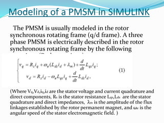
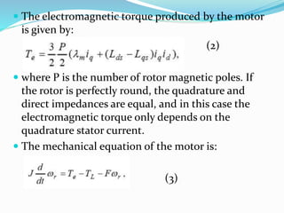
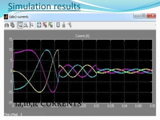
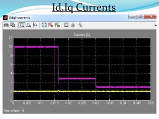
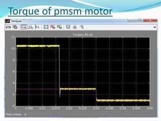
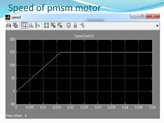


This document summarizes the modeling of a permanent magnet synchronous motor (PMSM) in Simulink. It describes how a PMSM is modeled in the rotor synchronous reference frame using Park equations. It discusses how the electromagnetic torque produced by the motor depends on the quadrature stator current. It also describes how the speed is controlled by controlling the electromagnetic torque through regulating the quadrature current. Finally, it presents the simulation results for the currents, torque, and speed of the modeled PMSM motor.