This document discusses modeling and field oriented control (FOC) of a permanent magnet synchronous motor (PMSM) using MATLAB/Simulink. It first introduces PMSM drives and their components. It then presents the mathematical modeling of a PMSM in the d-q reference frame. This includes developing the voltage and flux linkage equations. It also discusses Parks transformation and the equivalent circuit model. Next, it covers PMSM control strategies like FOC which allows controlling the motor like a DC motor. It provides the details of FOC implementation including constant torque control. Finally, it discusses establishing the FOC simulation model in MATLAB/Simulink to simulate the control system.
![E-ISSN: 2321–9637
Volume 2, Issue 1, January 2014
International Journal of Research in Advent Technology
Available Online at: http://www.ijrat.org
375
Figure 1 Drive system schematic
Permanent magnet synchronous motor (PMSM) is a motor that uses permanent magnets to produce the air gap
magnetic field rather than using electromagnets. Operation of permanent magnet synchronous motors requires
position sensors in the rotor shaft when operated without damper winding. There are four main devices for the
measurement of position, the potentiometer, linear variable differential transformer, optical encoder and
resolvers. The motor is fed form a voltage source inverter with current control. The control is performed by
regulating the flow of current through the stator of the motor.
1.2. Detailed Modeling of PMSM
The d-q model has been developed on rotor reference frame as shown in Fig. 2. At any time t, the rotating rotor
d-axis makes and angle θr with the fixed stator phase axis and rotating stator mmf makes an angle α with the
rotor d-axis. Stator mmf rotates at the same speed as that of the rotor [Sebastian et al (1986)].
Figure 2 Axis representation of Motor
The model of PMSM without damper winding has been developed on rotor reference frame using the following
assumptions [Sebastian et al (1986), Wang X et al (2009)]:
1) Saturation is neglected.
2) The induced EMF is sinusoidal.
3) Eddy currents and hysteresis losses are negligible.
4) There are no field current dynamics.
Voltage equations are given by:
(1)
(2)
Flux Linkages are given by
(3)
(4)
Substituting Eq. (3) and (4) into Eq. (1) and (2),
(5)](https://image.slidesharecdn.com/paperid-212014121-140828021222-phpapp01/85/Paper-id-212014121-2-320.jpg)
![E-ISSN: 2321–9637
Volume 2, Issue 1, January 2014
International Journal of Research in Advent Technology
Available Online at: http://www.ijrat.org
376
(6)
Arranging Eq. (5) and Eq. (6) in matrix form,
(7)
The developed torque motor is being given by,
(8)
The mechanical Torque equation is,
(9)
Solving for the rotor mechanical speed form Eq. (9),
(10)
And
(11)
In the above equations ωr is the rotor electrical speed where as ωm is the rotor mechanical speed.
1.2.1. Parks Transformation and Dynamic d-q Modeling
The dynamic d q modeling is used for the study of motor during transient and steady state. It is done by
converting the three phase voltages and currents to dqo variables by using Parks transformation [Macbahi H. et
al, (2000)]. Converting the phase voltages variables Vabc to Vdqo variables in rotor reference frame the following
equations are obtained
(12)
Convert Vdqo to Vabc
(13)
1.2.2. Equivalent Circuit of Permanent Magnet Synchronous Motor
Equivalent circuits of the motors are used for study and simulation of motors. From the d-q modeling of the
Figure 3 PMSM electric circuit](https://image.slidesharecdn.com/paperid-212014121-140828021222-phpapp01/85/Paper-id-212014121-3-320.jpg)
![E-ISSN: 2321–9637
Volume 2, Issue 1, January 2014
International Journal of Research in Advent Technology
Available Online at: http://www.ijrat.org
377
motor using the stator voltage equations the equivalent circuit of the motor can be derived. Assuming rotor d
axis flux from the permanent magnets is represented by a constant current source as described in the following
equation λf = Ldmif, and Fig. 3 is obtained.
1.3. PM Motor Control
Control of PM motors is performed using field oriented control for the operation of synchronous motor as a dc
motor [Wang X et al (2009)]. The stator windings of the motor are fed by an inverter that generates a variable
frequency variable voltage. Instead of controlling the inverter frequency independently, the frequency and phase
of the output wave are controlled using a position sensor as shown in Fig. 4
Figure 4 Drive system schematic.
Some control options are constant torque and flux weakening. These options are based in the physical limitation
of the motor and the inverter. The limit is established by the rated speed of the motor, at which speed the
constant torque operation finishes and the flux weakening starts as shown in Fig. 5.
Figure 5 Torque-speed characteristic in steady state
1.3.1. Field Oriented Control of PM Motors
Field oriented control was invented in the beginning of 1970s and it demonstrates that an induction motor or
synchronous motor could be controlled like a separately excited dc motor by the orientation of the stator mmf or
current vector in relation to the rotor flux to achieve a desired objective. In order for the motor to behave like
DC motor, the control needs knowledge of the position of the instantaneous rotor flux or rotor position of
permanent magnet motor. This needs a resolver or an absolute optical encoder. Knowing the position, the three
phase currents can be calculated. Its calculation using the current matrix depends on the control desired.
The PMSM control is equivalent to that of the dc motor by a decoupling control known as field oriented control
or vector control. The vector control separates the torque component of current and flux channels in the motor
through its stator excitation. The vector control of the PM synchronous motor is derived from its dynamic model
[Wang X et al (2009)].
Considering the currents as inputs, the three currents are:
(14)
(15)
(16)](https://image.slidesharecdn.com/paperid-212014121-140828021222-phpapp01/85/Paper-id-212014121-4-320.jpg)
![E-ISSN: 2321–9637
Volume 2, Issue 1, January 2014
International Journal of Research in Advent Technology
Available Online at: http://www.ijrat.org
378
Where α is the angle between the rotor field and stator current phasor, ωr is the electrical rotor speed.
Figure 6 Block diagram of field oriented vector control system for PMSM
The block diagram of field oriented vector control system is shown below. The previous currents obtained are
the stator currents that must be transformed to the rotor reference frame with the rotor speed ωr, using Park’s
transformation [XU Jun-Feng et al, (2005)]. The q and d axis currents are constants in the rotor reference frames
since α is a constant for a given load torque. As these constants, they are similar to the armature and field
currents in the separately excited dc machine. The q axis current is distinctly equivalent to the armature current
of the dc machine; the d axis current is field current, but not in its entirety. It is only a partial field current; the
other part is contributed by the equivalent current source representing the permanent magnet field. Id and iq in
terms of Im as follows
(17)
Using Eq. (1), (2), (8) and (17) the electromagnetic torque equation is obtained as given below.
(18)
1.3.2. Constant torque operation
This is performed by making the torque producing current iq equal to the supply current Im. That results in
selecting the α angle to be 90 º degrees according to Eq. (17). By making the id current equal to zero the torque
equation can be rewritten as [Song K., Liu W., (2008)]:
(19)
This indicates that like the dc motor, the torque is dependent of the motor current.
2. THE ESTABLISHMENT OF THE FOC SIMULATION MODEL
Mathematical model of permanent magnet motor has been developed using Eq. (1) to (19). Simulation has been
Table 2 PMSM parameters
Ld 0.0066
Lq 0.0058
Ma Rs 1.4
P 6
B 0.00038818
J 0.001760
λf 0.1546](https://image.slidesharecdn.com/paperid-212014121-140828021222-phpapp01/85/Paper-id-212014121-5-320.jpg)
![E-ISSN: 2321–9637
Volume 2, Issue 1, January 2014
International Journal of Research in Advent Technology
Available Online at: http://www.ijrat.org
379
carried out for vector control in which field oriented control strategy is selected for motor. Table 2 shows
parameters of PMSM motor for which simulation is carried out [Bose B. K., (2002)].
2.1. MATLAB Model
After analyzing the mathematical model of PMSM and the principle of field-oriented vector control system, the
simulation model of field-oriented control system is established. The simulation model is under the environment
of MATLAB7.0/Simulink using, due to its rich module libraries [Ong C.-m., (1998), Macbahi H. et al, (2000)].
The system structure is shown as figure 7, and the main simulation modules are introduced as follows:
Figure 7 FOC system simulation diagram based on SPWM
2.1.1. PMSM Motor Modeling:
By using Eq. (1) to (13), we can develop the PMSM motor model in MATLAB/ Simulink as shown in figure.
Figure 8 Mathematical model of PMSM
2.1.2. SPWM:
In this design the Sinusoidal Pulse Width Modulation (SPWM) technique has been used for controlling the
inverter as it can be directly controlled the inverter output voltage and output frequency according to the sine
functions. SPWM techniques are characterized by constant amplitude pulses with different duty cycles for each
period. In SPWM technique three sine waves and a high frequency triangular carrier wave are used to generate
PWM signal. Generally, three sinusoidal waves are used for three phase inverter. The sinusoidal waves are
called reference signal and they have 120 phase difference with each other. The frequency of these sinusoidal
waves is chosen based on the required inverter output frequency (50 Hz). The carrier triangular wave is usually
a high frequency (in several KHz) wave. The switching signal is generated by comparing the sinusoidal waves
with the triangular wave. The comparator gives out a pulse when sine voltage is greater than the triangular
voltage and this pulse is used to trigger the respective inverter switches. Conventional SPWM signal generation
technique in MATLAB/Simulink environment for three phase voltage source inverter is shown in Fig. 9.](https://image.slidesharecdn.com/paperid-212014121-140828021222-phpapp01/85/Paper-id-212014121-6-320.jpg)
![E-ISSN: 2321–9637
Volume 2, Issue 1, January 2014
International Journal of Research in Advent Technology
Available Online at: http://www.ijrat.org
381
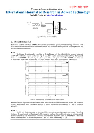
Figure 11 Simulation result for constant speed and change in load
During this period the actual speed of the motor just deviate from its reference for few second and again achieve
its reference on increased load. again at time t=7 second the load torque is reduced to 1 Nm again and the motor
achieve its reference speed of 200 RPM after deviating a little bit due to change in load.
4. CONCLUSION
In this paper mathematical modeling of PMSM is carried out using MATLAB. Switching sequence of inverter is
generated by sinusoidal pulse width modulation. Field oriented vector control is quite precise and gives the
precise control to the motor speed. By FOC we can run the motor synchronously at any sudden load change.
References
[1] Bose B. K., (2002), “Modern power electronics and AC drives”, Prentice Hall.
[2] Macbahi H., Ba-razzouk A., Xu J., Cheriti A., and Rajagopalan V., (2000), “A unified method for modeling and
simulation of three phase induction motor drives”.
[3] Ong C.-m., (1998), “Dynamic Simulation of Electric Machinery using Matlab/Simulink” Prentice Hall.
[4] Pillay P. and Krishnan R., (1988), “Modeling of permanent magnet motor drives.” Industrial Electronics, IEEE
Transactions on, vol. 35, pp. 537-541.
[5] Song K., Liu W., (2008), “Permanent Magnet Synchronous Motor Field Oriented Control and HIL Simulation.” IEEE
Vehicle Power and Propulsion Conference, Harbin, pp.4-6.
[6] Sebastian T., Slemon G., and Rahman M., (1986), "Modelling of permanent magnet synchronous motors," Magnetics,
IEEE Transactions on, vol. 22, pp. 1069-1071.
[7] Wang X., Risha N., Liu N., (2009), “Simulation of PMSM Field-Oriented Control Based on SVPWM”, IEEE Vehicle
Power and Propulsion Conference, VPPC.
[8] XU Jun-Feng, FENG Jiang-Hua, XU Jian-Hua, (2005), “Control policy of permanent magnetism synchronous motor
summery.” The electrical trasimissionof Locomotive, pp.7-11](https://image.slidesharecdn.com/paperid-212014121-140828021222-phpapp01/85/Paper-id-212014121-8-320.jpg)