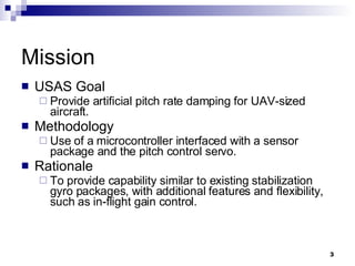
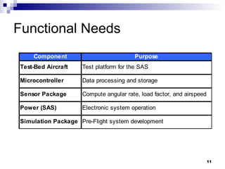
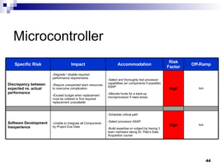
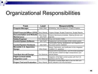
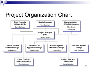
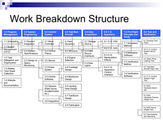
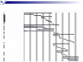
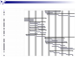
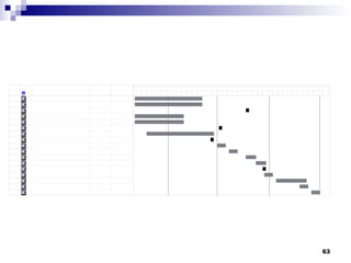
UAV Stability Augmentation System - USAS Tom Bateman Barry Blakeley Adam Dean Jake Hanft Mike Sheek
Outline Mission Objectives Overview Development and Assessment of Design Alternatives Design-To Specifications Risk Assessment Project Plan
Mission USAS Goal Provide artificial pitch rate damping for UAV-sized aircraft. Methodology Use of a microcontroller interfaced with a sensor package and the pitch control servo. Rationale To provide capability similar to existing stabilization gyro packages, with additional features and flexibility, such as in-flight gain control.
Stretch  Goals Load Factor Limiting Stall Prevention / Recovery Artificial Stabilization of Marginally Stable / Unstable Configuration Command Augmentation (Enhanced Maneuverability)
Overview of Objectives Design alternatives Functional Needs Identify Central Design Parameters and Drivers Performance Metrics Comparison with Alternatives
Overview of Objectives Design-to Specifications System Architecture Functional Elements Performance Target Procurement Requirements
Overview of Objectives Risk assessment Identify Design Issues and Risks Backup Plan s Specify Off-Ramp Dates Where Needed
Overview of Objectives Project plan Organizational Chart Work Breakdown Structure (WBS) Schedule Cost Estimates Facilities and Resources
Jake Hanft Development and Assessment of Design Alternatives
Development and Assessment of Design Alternatives Functional Needs Design Parameters Driving Design Considerations Performance Metrics and Analysis Comparison of Design Alternatives
Functional Needs
Test-Bed Aircraft Design Parameters Room for SAS House moveable cg apparatus Appropriate flying qualities for testing SAS Custom Built Facilitate moveable C.G apparatus House SAS Kit Modification of kit would be required Ability to find suitable electric model
Microcontroller Driving Design Considerations Enough PWM for expandability for future applications Facilitate timing requirements of SAS Adequate number of ADC channels
Microcontroller (cont.) Possible Choices Microchip PIC18F458 (QuikFlash Board) Apply ASEN 4519 knowledge Large expandable development board ATMEL ATMEGA 128L (NAIAD Board) CU student built Prior use and knowledge Motorola #1 market share industry provider  Performance history OOPIC Easily programmable
Sensor Package Design Parameters Rate Gyro Max angular rate: ~135 deg/s Accelerometer Max load factor: ~12 g Pressure Transducer Range: 0 - 0.16 psi
Sensor Package (cont.) Rate Gyros Analog Devices Best with vibration $50 on evaluation board Piezo Gyro Cannibalize from Futaba gyro package ~$120 Accelerometer Analog Devices  Readily available free samples ASEN 3300 experience
Sensor Package (cont.) Pressure Transducer Honeywell Sub-miniature Various ranges  $30 and up Omega Large selection of PC mountable transducers $59 and up Larger size than Honeywell
Simulation Package Overall Objective Test control package and other subsystems prior to flight test Numerical Simulation (SimuLink) Determine aircraft natural frequency to properly design control algorithms
Power Main Propulsion 30-cell, 1900 mAH Ni-Cd battery pack Cheapest and readily available battery Flight Control Sub-System (FCSS) Standard Ni-Cd receiver battery SAS May share FCSS power supply Alternative – separate battery pack
Design Metric (Microcontrollers)
Design Metric (Test-Bed Aircraft, Sensors and Power Configuration) Independent Adds extra weight but may be necessary 1 Score:  1   Rating:  High Cost:  ?   Rating:  Low Cost:  Free   Rating:  Low Score:  1   Rating:  High 1 Eliminate the need to add another battery back just for the SAS, however, the receiver battery may not carry enough voltage to do this. Tap into Reciever's Power Power Configuration 0 PC board mountable, but difficult configuration compared to PX139 Cost:  $40   Rating:  Low Score:  1  Rating:  Low 1 Good range, 5V operation Omega PX71-0.3GV 0 The extra voltage may require an independent power source Cost:  $85   Rating:  Low Score:  1   Rating:  Low 1 Good range, 8V operation Omega PX138-0.3D5v 1 Has just enough range and has a 5V operating level enabling power through same output as microcontroller Cost:  $85   Rating:  Low Score:  2  Rating:  High 1 Good range, 5V operation Omega PX139-0.3D5V Pressure Transducer 0 Does not have large enough range Cost:  Free   Rating:  Low Score: -1   Rating:  Low -1 ±10 g Dual Axis Accelerometer with Duty Cycle Outputs Analog Devices ADXL210 1 Can be programmable to ±25 g Cost:  Free   Rating:  Low Score:  2   Rating:  High 1 ±50g Dual Axis Accelerometer with Analog Outputs Analog Devices ADXL250 Accelerometer Cost:  $120  Rating:  Low Score:  1  Rating:  Low 1 Would have to take from Futaba package Piezo 1 MEM device with excellent noise handling Cost:  $50   Rating:  Low Score:  2   Rating:  High 1 150 deg/s, can come packaged on an evaluation board Analog Devices ADXL150 2 MEM device with excellent noise handling and larger range Cost:  $50   Rating:  Low Score: 3   Rating:  High 1 300 deg/s, can come packaged on an evalutation board Analog Devices ADXL300 Rate Gyro Low Low 1 Would not have to spend time designing an airplane, however, it would be just as time consuming to redesign a kit. The balsa construction would not be nearly as robust as the custom fiberglass. Kit Low High 3 By building a custom plane, we can custom fit the control package, as well as incorporate a moveable cg apparatus. Also, we will be able to vary the tail length and be able to test the SAS on different configurations easily Custom Test-Bed Aircraft Cost Attributes Scale Specs and Comments Manufacturer/Part Component
Comparison of Design Alternatives Results
Design-To Specifications Tom Bateman HYPER-X USAS
Design-To Specifications System Architecture Functional Elements Required Performance Parameters Procurement Requirements
General Arrangement Cargo Bay 3.75” x 5.5” x 10” R/C Receivers (2) Powerplant Astro 661/APC 15x7 Tailboom Adjustable Length CG Apparatus Inflight Adjustable
Major Aircraft Subsystems Pitch (y) (SAS Control Axis) Roll (x) Yaw (z) Powerplant Electric Motor (.60 size) 30 cell NiCd Main Battery Primary Flight Control System R/C Receiver (Rx) Rx Battery (Shared by SAS) Servos (Rudder, Aileron) Motor Speed Control SAS Electronics and Sensor Package Microcontroller Pitch Rate Gyro Pressure Transducer Linear Accelerometer CG Control System Sail Winch Servo Balance Weight Pitch Control High Speed Digital Servo Elevator
SAS Block Diagram MICROCONTROLLER PITCH  RATE GYRO DATA ACQUISITION PILOT PITCH SIGNAL PILOT + SAS PITCH SIGNAL CG CONTROL  SERVO BALANCE WEIGHT GAIN CONTROL MANUAL CG CONTROL PRESSURE  TRANSDUCER LINEAR ACCELEROMETER PCS FEEDBACK SIGNAL COMMAND OVERRIDE CGS FEEDBACK SIGNAL SAS  BATTERY Rx  BATTERY AUTO CG CONTROL CG CONTROL PCS BYPASS POWER COMMANDS OUTPUTS SENSORS Legend R/C  TRANSMITTER R/C RECEIVER P/C  SERVO ELEVATOR
Electronics Chassis Microcontroller PIC18F458 Rate Gyro Pressure Transducer Accelerometer Chassis QuikFlash Board
Controller Board Schematic PITCH COMMAND PWMD PITCH  RATE CG CONTROL  FEEDBACK DYNAMIC PRESSURE  Z-AXIS ACCELERATION PITCH  COMMAND GAIN CONTROL COMMAND OVERRIDE MICROCONTROLLER V REF A/D A/D 0/1 A/D A/D A/D PWMD PWM PITCH FEEDBACK A/D A/D REG DATA ACQUISITION (EXTERNAL RAM) 0101… VDD 6-9 VDC CG COMMAND PWM CG CONTROL PWMD A/D POWER INTERRUPT DATA SWITCH 0/1 POWER COMMANDS OUTPUTS FEEDBACK SENSORS Legend
Control Process Flow Start (power on) Initialize variables Pitch rate Read sensor inputs Pilot command Gain control Dynamic pressure Read command inputs Command override Z-axis acceleration Read feedback inputs Elevator servo CG Servo Estimate commanded pitch rate Compute PR error Apply control gain Compute elevator deflection Output elevator control signal Pitch command A/D A/D A/D PWM PWM 0/1 A/D A/D PWM Output data acquisition External  Flash RAM   0101… Apply SAS  Authority Limiting Watchdog/ Brownout Timing Loop Command Override ? Bypass pitch control CG control PWM N Y Command CG  to full forward CG command PWM Bypass CG control Data switch 0/1 Data switch 0/1 Primary Control Algorithm
Sensors, Actuators, Electronics
Simulink Model
Simulink Model (Detail)
System Dynamic Response Step Input System Off System On Turbulence System Off System On
Wing Aerodynamic and Structural Model
SAS Performance Target
Test-Bed Aircraft Specifications
CG Control System Specifications
Data Acquisition Specifications
Simulation Specifications
Design Issues and Risk Assessment Mike Sheek
Test-Bed Aircraft N/A High -Ensure that an experienced pilot flies  Aircraft -Select an ‘Almost Ready to Fly' model  to use in re-building effort -Ensure that all pre-flight tests and  precautions have been made before flight tests -Require intense last minute build  effort -Inability to verify SAS in RC aircraft Test-bed aircraft mishap prior to SAS tests Off-Ramp: March 19 th If SAS cannot be  integrated by this date  prioritization will move to  developing alternative  testing apparatus Medium -Develop test-bed aircraft in parallel with SAS -Develop back-up testing apparatus to test SAS capabilities -Require unexpected team  resources to overcome complication Unable to integrate the SAS with the  test-bed Aircraft Off-Ramp Risk  Factor Accommodations Impact Specific Risk
Microcontroller N/A High -Select and thoroughly test processor capabilities (w/ components if possible) ASAP -Allocate funds for a back-up microprocessor if need arises -Degrade / disable required performance requirements -Require unexpected team resources to overcome complication -Exceed budget when replacement must be ordered or find required replacement unavailable Discrepancy between expected vs. actual performance N/A High -Schedule critical path -Select processor ASAP -Build expertise on subject by having 3 team members taking Dr. Palo’s Data Acquisition course -Unable to integrate all Components by Project Due Date Software Development Inexperience Off-Ramp Risk Factor Accommodation Impact Specific Risk
Presented by Adam Dean Project Management Plan
Organizational Responsibilities
Project Organization Chart Movable CG Apparatus Design -Mike Sheek- Project Manager (PM) -Adam Dean- Chief Financial Officer (CFO) -Barry Blakeley- Documentation / Web Maintenance -Mike Sheek- -Jake Hanft- Project Test and Evaluation -Barry Blakeley- Flight Control / USAS Integration -Tom Bateman- Control System Software Design -Jake Hanft- Control System Hardware Design -Jake Hanft Test-Bed Aircraft Design - Tom Bateman- Safety Engineer -Tom Bateman-
Work Breakdown Structure 1.0 Program Management 2.0 System Engineering 3.0 Control System 6.0 C.G. Apparatus 4.0 Test-Bed Aircraft 5.0 Data Acquisition 7.0 Pre-Flight Simulate and Verify 1.1 Budget Management (CFO) 1.2 Task Delegation and Organization 1.4 Website and Documentation 1.3 Weekly Time Sheet Collection 1.1 Scheduling 2.1System Integration 2.2 System Specifications 2.3 Design to Specs. Monitoring 3.1 Micro Controller 3.2 Control Theory 3.2 Servos 3.4 Control Software 4.3 Engine Selection 4.2 Structure 4.1Aero Dynamics 3.3 Power System 5.1 Storage Device 3.5 Sensors (Rate Gyros, Accelerometer, etc.) 3.6 Integration 4.7 Tail-Boom Design 4.5 Backbone Design 4.4 Fuselage Design 5.2 Data Source Interfaces 4.6 Landing Gear Design 5.3 Data Uplink 6.3 C.G. Manipulation Effects 6.1 C.G. H/W 6.2 C.G. S/W 6.4 C.G. Apparatus Control Interface 8.0 Test and Verification 8.1 Develop Test Plans 4.8 Fabrication 8.3 Test analysis and Reporting 8.2 C.G. Control System Bench Test 8.3 SAS Hardware Bench test 8.2 Static Wing Loading Test 8.3 Test-Bed Aircraft Flight Test 8.2 C.G. Control System Flight Test 8.3 SAS Hardware Passive Inflight Test 8.2 SAS Active Inflight Test 7.2 Simulation Software 7.1 Simulation Method 7.4 Verification Software 7.3 Verification Method
Test and Evaluation Program CG Control System  Bench Test Due ~ 3/5/04   SAS Hardware  Passive Inflight Test Due ~ 4/2/04 Data Analysis Due ~ 4/29 SAS Hardware  Active Inflight Test Due ~ 4/22/04 CG Control System Flight Test Due ~ 3/29/04 Test-Bed Aircraft Flight Test Due ~ 3/23/04 Static Wing Loading Test Due ~ 10/903 SAS Hardware Bench Test Due ~   3/12/04
Program Schedule
Program Schedule
Estimated Cost Breakdown
Preliminary Drawing Tree
Specialized Facilities and Resources Desired Seminars CAD Control Systems/Microcontroller Data Acquisition System Integration Measurement System Wind Tunnel/Chamber Aircraft Test Airspace
Team USAS Questions
Back-Up Charts
System Functional Elements
Program Schedule
Program Schedule
Program Schedule

Uav Stability Augmentation System Usas

  • 1.
    UAV Stability AugmentationSystem - USAS Tom Bateman Barry Blakeley Adam Dean Jake Hanft Mike Sheek
  • 2.
    Outline Mission ObjectivesOverview Development and Assessment of Design Alternatives Design-To Specifications Risk Assessment Project Plan
  • 3.
    Mission USAS GoalProvide artificial pitch rate damping for UAV-sized aircraft. Methodology Use of a microcontroller interfaced with a sensor package and the pitch control servo. Rationale To provide capability similar to existing stabilization gyro packages, with additional features and flexibility, such as in-flight gain control.
  • 4.
    Stretch GoalsLoad Factor Limiting Stall Prevention / Recovery Artificial Stabilization of Marginally Stable / Unstable Configuration Command Augmentation (Enhanced Maneuverability)
  • 5.
    Overview of ObjectivesDesign alternatives Functional Needs Identify Central Design Parameters and Drivers Performance Metrics Comparison with Alternatives
  • 6.
    Overview of ObjectivesDesign-to Specifications System Architecture Functional Elements Performance Target Procurement Requirements
  • 7.
    Overview of ObjectivesRisk assessment Identify Design Issues and Risks Backup Plan s Specify Off-Ramp Dates Where Needed
  • 8.
    Overview of ObjectivesProject plan Organizational Chart Work Breakdown Structure (WBS) Schedule Cost Estimates Facilities and Resources
  • 9.
    Jake Hanft Developmentand Assessment of Design Alternatives
  • 10.
    Development and Assessmentof Design Alternatives Functional Needs Design Parameters Driving Design Considerations Performance Metrics and Analysis Comparison of Design Alternatives
  • 11.
  • 12.
    Test-Bed Aircraft DesignParameters Room for SAS House moveable cg apparatus Appropriate flying qualities for testing SAS Custom Built Facilitate moveable C.G apparatus House SAS Kit Modification of kit would be required Ability to find suitable electric model
  • 13.
    Microcontroller Driving DesignConsiderations Enough PWM for expandability for future applications Facilitate timing requirements of SAS Adequate number of ADC channels
  • 14.
    Microcontroller (cont.) PossibleChoices Microchip PIC18F458 (QuikFlash Board) Apply ASEN 4519 knowledge Large expandable development board ATMEL ATMEGA 128L (NAIAD Board) CU student built Prior use and knowledge Motorola #1 market share industry provider Performance history OOPIC Easily programmable
  • 15.
    Sensor Package DesignParameters Rate Gyro Max angular rate: ~135 deg/s Accelerometer Max load factor: ~12 g Pressure Transducer Range: 0 - 0.16 psi
  • 16.
    Sensor Package (cont.)Rate Gyros Analog Devices Best with vibration $50 on evaluation board Piezo Gyro Cannibalize from Futaba gyro package ~$120 Accelerometer Analog Devices Readily available free samples ASEN 3300 experience
  • 17.
    Sensor Package (cont.)Pressure Transducer Honeywell Sub-miniature Various ranges $30 and up Omega Large selection of PC mountable transducers $59 and up Larger size than Honeywell
  • 18.
    Simulation Package OverallObjective Test control package and other subsystems prior to flight test Numerical Simulation (SimuLink) Determine aircraft natural frequency to properly design control algorithms
  • 19.
    Power Main Propulsion30-cell, 1900 mAH Ni-Cd battery pack Cheapest and readily available battery Flight Control Sub-System (FCSS) Standard Ni-Cd receiver battery SAS May share FCSS power supply Alternative – separate battery pack
  • 20.
  • 21.
    Design Metric (Test-BedAircraft, Sensors and Power Configuration) Independent Adds extra weight but may be necessary 1 Score: 1 Rating: High Cost: ? Rating: Low Cost: Free Rating: Low Score: 1 Rating: High 1 Eliminate the need to add another battery back just for the SAS, however, the receiver battery may not carry enough voltage to do this. Tap into Reciever's Power Power Configuration 0 PC board mountable, but difficult configuration compared to PX139 Cost: $40 Rating: Low Score: 1 Rating: Low 1 Good range, 5V operation Omega PX71-0.3GV 0 The extra voltage may require an independent power source Cost: $85 Rating: Low Score: 1 Rating: Low 1 Good range, 8V operation Omega PX138-0.3D5v 1 Has just enough range and has a 5V operating level enabling power through same output as microcontroller Cost: $85 Rating: Low Score: 2 Rating: High 1 Good range, 5V operation Omega PX139-0.3D5V Pressure Transducer 0 Does not have large enough range Cost: Free Rating: Low Score: -1 Rating: Low -1 ±10 g Dual Axis Accelerometer with Duty Cycle Outputs Analog Devices ADXL210 1 Can be programmable to ±25 g Cost: Free Rating: Low Score: 2 Rating: High 1 ±50g Dual Axis Accelerometer with Analog Outputs Analog Devices ADXL250 Accelerometer Cost: $120 Rating: Low Score: 1 Rating: Low 1 Would have to take from Futaba package Piezo 1 MEM device with excellent noise handling Cost: $50 Rating: Low Score: 2 Rating: High 1 150 deg/s, can come packaged on an evaluation board Analog Devices ADXL150 2 MEM device with excellent noise handling and larger range Cost: $50 Rating: Low Score: 3 Rating: High 1 300 deg/s, can come packaged on an evalutation board Analog Devices ADXL300 Rate Gyro Low Low 1 Would not have to spend time designing an airplane, however, it would be just as time consuming to redesign a kit. The balsa construction would not be nearly as robust as the custom fiberglass. Kit Low High 3 By building a custom plane, we can custom fit the control package, as well as incorporate a moveable cg apparatus. Also, we will be able to vary the tail length and be able to test the SAS on different configurations easily Custom Test-Bed Aircraft Cost Attributes Scale Specs and Comments Manufacturer/Part Component
  • 22.
    Comparison of DesignAlternatives Results
  • 23.
    Design-To Specifications TomBateman HYPER-X USAS
  • 24.
    Design-To Specifications SystemArchitecture Functional Elements Required Performance Parameters Procurement Requirements
  • 25.
    General Arrangement CargoBay 3.75” x 5.5” x 10” R/C Receivers (2) Powerplant Astro 661/APC 15x7 Tailboom Adjustable Length CG Apparatus Inflight Adjustable
  • 26.
    Major Aircraft SubsystemsPitch (y) (SAS Control Axis) Roll (x) Yaw (z) Powerplant Electric Motor (.60 size) 30 cell NiCd Main Battery Primary Flight Control System R/C Receiver (Rx) Rx Battery (Shared by SAS) Servos (Rudder, Aileron) Motor Speed Control SAS Electronics and Sensor Package Microcontroller Pitch Rate Gyro Pressure Transducer Linear Accelerometer CG Control System Sail Winch Servo Balance Weight Pitch Control High Speed Digital Servo Elevator
  • 27.
    SAS Block DiagramMICROCONTROLLER PITCH RATE GYRO DATA ACQUISITION PILOT PITCH SIGNAL PILOT + SAS PITCH SIGNAL CG CONTROL SERVO BALANCE WEIGHT GAIN CONTROL MANUAL CG CONTROL PRESSURE TRANSDUCER LINEAR ACCELEROMETER PCS FEEDBACK SIGNAL COMMAND OVERRIDE CGS FEEDBACK SIGNAL SAS BATTERY Rx BATTERY AUTO CG CONTROL CG CONTROL PCS BYPASS POWER COMMANDS OUTPUTS SENSORS Legend R/C TRANSMITTER R/C RECEIVER P/C SERVO ELEVATOR
  • 28.
    Electronics Chassis MicrocontrollerPIC18F458 Rate Gyro Pressure Transducer Accelerometer Chassis QuikFlash Board
  • 29.
    Controller Board SchematicPITCH COMMAND PWMD PITCH RATE CG CONTROL FEEDBACK DYNAMIC PRESSURE Z-AXIS ACCELERATION PITCH COMMAND GAIN CONTROL COMMAND OVERRIDE MICROCONTROLLER V REF A/D A/D 0/1 A/D A/D A/D PWMD PWM PITCH FEEDBACK A/D A/D REG DATA ACQUISITION (EXTERNAL RAM) 0101… VDD 6-9 VDC CG COMMAND PWM CG CONTROL PWMD A/D POWER INTERRUPT DATA SWITCH 0/1 POWER COMMANDS OUTPUTS FEEDBACK SENSORS Legend
  • 30.
    Control Process FlowStart (power on) Initialize variables Pitch rate Read sensor inputs Pilot command Gain control Dynamic pressure Read command inputs Command override Z-axis acceleration Read feedback inputs Elevator servo CG Servo Estimate commanded pitch rate Compute PR error Apply control gain Compute elevator deflection Output elevator control signal Pitch command A/D A/D A/D PWM PWM 0/1 A/D A/D PWM Output data acquisition External Flash RAM 0101… Apply SAS Authority Limiting Watchdog/ Brownout Timing Loop Command Override ? Bypass pitch control CG control PWM N Y Command CG to full forward CG command PWM Bypass CG control Data switch 0/1 Data switch 0/1 Primary Control Algorithm
  • 31.
  • 32.
  • 33.
  • 34.
    System Dynamic ResponseStep Input System Off System On Turbulence System Off System On
  • 35.
    Wing Aerodynamic andStructural Model
  • 36.
    Wing Aerodynamic andStructural Model
  • 37.
  • 38.
  • 39.
    CG Control SystemSpecifications
  • 40.
  • 41.
  • 42.
    Design Issues andRisk Assessment Mike Sheek
  • 43.
    Test-Bed Aircraft N/AHigh -Ensure that an experienced pilot flies Aircraft -Select an ‘Almost Ready to Fly' model to use in re-building effort -Ensure that all pre-flight tests and precautions have been made before flight tests -Require intense last minute build effort -Inability to verify SAS in RC aircraft Test-bed aircraft mishap prior to SAS tests Off-Ramp: March 19 th If SAS cannot be integrated by this date prioritization will move to developing alternative testing apparatus Medium -Develop test-bed aircraft in parallel with SAS -Develop back-up testing apparatus to test SAS capabilities -Require unexpected team resources to overcome complication Unable to integrate the SAS with the test-bed Aircraft Off-Ramp Risk Factor Accommodations Impact Specific Risk
  • 44.
    Microcontroller N/A High-Select and thoroughly test processor capabilities (w/ components if possible) ASAP -Allocate funds for a back-up microprocessor if need arises -Degrade / disable required performance requirements -Require unexpected team resources to overcome complication -Exceed budget when replacement must be ordered or find required replacement unavailable Discrepancy between expected vs. actual performance N/A High -Schedule critical path -Select processor ASAP -Build expertise on subject by having 3 team members taking Dr. Palo’s Data Acquisition course -Unable to integrate all Components by Project Due Date Software Development Inexperience Off-Ramp Risk Factor Accommodation Impact Specific Risk
  • 45.
    Presented by AdamDean Project Management Plan
  • 46.
  • 47.
    Project Organization ChartMovable CG Apparatus Design -Mike Sheek- Project Manager (PM) -Adam Dean- Chief Financial Officer (CFO) -Barry Blakeley- Documentation / Web Maintenance -Mike Sheek- -Jake Hanft- Project Test and Evaluation -Barry Blakeley- Flight Control / USAS Integration -Tom Bateman- Control System Software Design -Jake Hanft- Control System Hardware Design -Jake Hanft Test-Bed Aircraft Design - Tom Bateman- Safety Engineer -Tom Bateman-
  • 48.
    Work Breakdown Structure1.0 Program Management 2.0 System Engineering 3.0 Control System 6.0 C.G. Apparatus 4.0 Test-Bed Aircraft 5.0 Data Acquisition 7.0 Pre-Flight Simulate and Verify 1.1 Budget Management (CFO) 1.2 Task Delegation and Organization 1.4 Website and Documentation 1.3 Weekly Time Sheet Collection 1.1 Scheduling 2.1System Integration 2.2 System Specifications 2.3 Design to Specs. Monitoring 3.1 Micro Controller 3.2 Control Theory 3.2 Servos 3.4 Control Software 4.3 Engine Selection 4.2 Structure 4.1Aero Dynamics 3.3 Power System 5.1 Storage Device 3.5 Sensors (Rate Gyros, Accelerometer, etc.) 3.6 Integration 4.7 Tail-Boom Design 4.5 Backbone Design 4.4 Fuselage Design 5.2 Data Source Interfaces 4.6 Landing Gear Design 5.3 Data Uplink 6.3 C.G. Manipulation Effects 6.1 C.G. H/W 6.2 C.G. S/W 6.4 C.G. Apparatus Control Interface 8.0 Test and Verification 8.1 Develop Test Plans 4.8 Fabrication 8.3 Test analysis and Reporting 8.2 C.G. Control System Bench Test 8.3 SAS Hardware Bench test 8.2 Static Wing Loading Test 8.3 Test-Bed Aircraft Flight Test 8.2 C.G. Control System Flight Test 8.3 SAS Hardware Passive Inflight Test 8.2 SAS Active Inflight Test 7.2 Simulation Software 7.1 Simulation Method 7.4 Verification Software 7.3 Verification Method
  • 49.
    Test and EvaluationProgram CG Control System Bench Test Due ~ 3/5/04 SAS Hardware Passive Inflight Test Due ~ 4/2/04 Data Analysis Due ~ 4/29 SAS Hardware Active Inflight Test Due ~ 4/22/04 CG Control System Flight Test Due ~ 3/29/04 Test-Bed Aircraft Flight Test Due ~ 3/23/04 Static Wing Loading Test Due ~ 10/903 SAS Hardware Bench Test Due ~ 3/12/04
  • 50.
  • 51.
  • 52.
  • 53.
  • 54.
  • 55.
  • 56.
  • 57.
    Specialized Facilities andResources Desired Seminars CAD Control Systems/Microcontroller Data Acquisition System Integration Measurement System Wind Tunnel/Chamber Aircraft Test Airspace
  • 58.
  • 59.
  • 60.
  • 61.
  • 62.
  • 63.