SlideShare a Scribd company logo
AIRCRAFT FUEL SYSTEM
CONTENT
 Description of Fuel System
 Different types of Fuel System
 Fuel System Components
 Types of fuel used
DESCRIPTION OF FUEL SYSTEM
The fuel system is designed to provide an
uninterrupted flow of clean fuel from the fuel tanks
to the engine. The fuel must be available to the
engine under all conditions of engine power,
altitude, attitude, and during all approved flight
maneuvers . Fuel systems differ greatly from
aircraft to aircraft due to the relative size and
complexity of the aircraft in which they are
installed. In the most basic form. a fuel system will
consist of a single, gravity feed fuel tank with the
associated fuel line connecting it to the aircraft
engine.
DIFFERENT TYPES OF FUEL SYSTEM
 Small Single-Engine Aircraft Fuel Systems
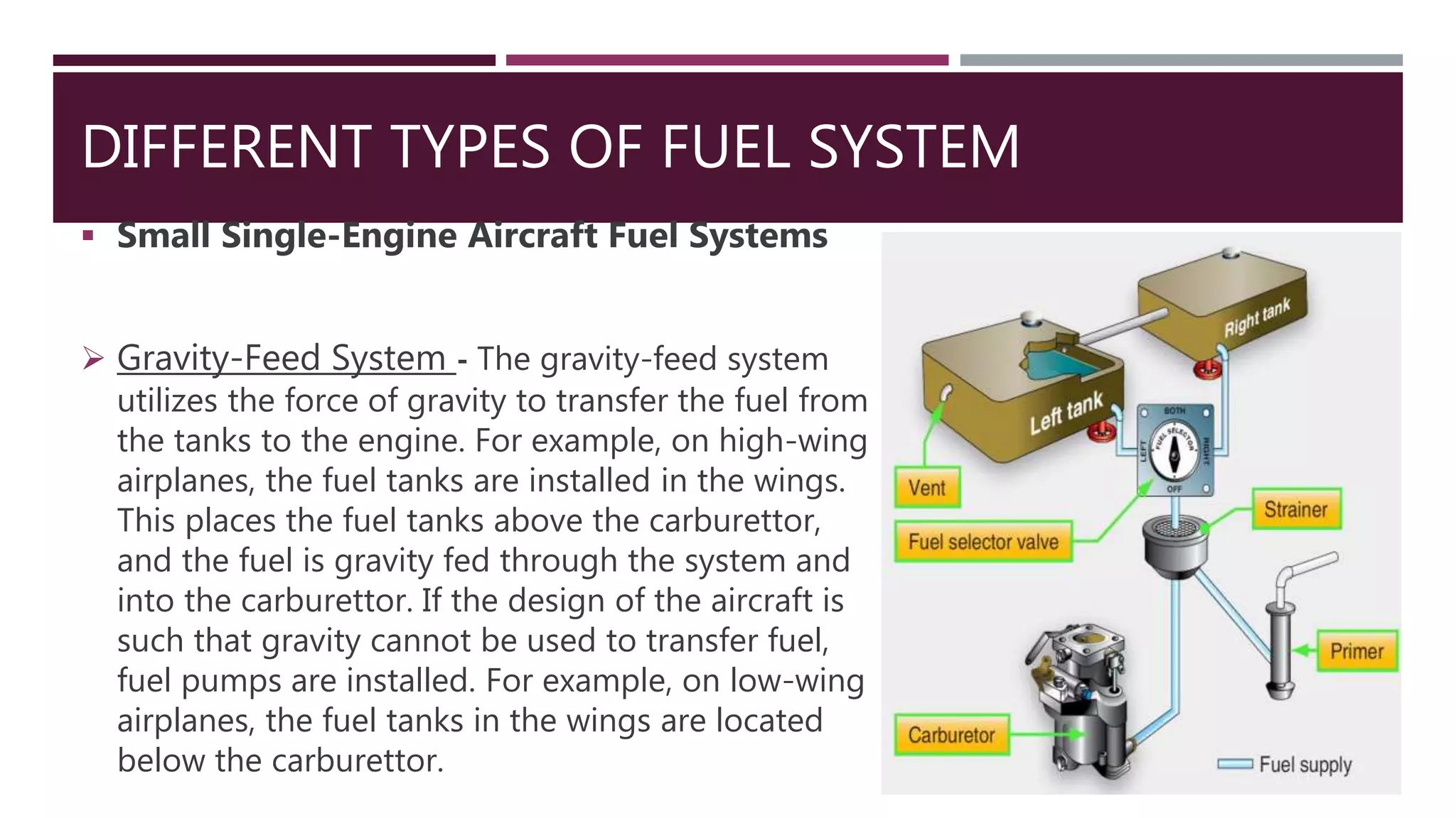
 Gravity-Feed System - The gravity-feed system
utilizes the force of gravity to transfer the fuel from
the tanks to the engine. For example, on high-wing
airplanes, the fuel tanks are installed in the wings.
This places the fuel tanks above the carburettor,
and the fuel is gravity fed through the system and
into the carburettor. If the design of the aircraft is
such that gravity cannot be used to transfer fuel,
fuel pumps are installed. For example, on low-wing
airplanes, the fuel tanks in the wings are located
below the carburettor.
 Fuel-Pump System - Aircraft with fuel-pump
systems have two fuel pumps. The main pump
system is engine driven with an electrically
driven auxiliary pump provided for use in
engine starting and in the event the engine
pump fails. The auxiliary pump, also known as a
boost pump, provides added reliability to the
fuel system. The electrically-driven auxiliary
pump is controlled by a switch in the flight
deck.
 Large Reciprocating-Engine Aircraft Fuel Systems
Large, multiengine transport aircraft powered by reciprocating radial engines are no longer
However, many are still in operation. A selector valve for each engine allows an engine-driven
to pull fuel from the main tank or an auxiliary tank. The fuel passes through a strainer before
the pump where it is delivered to the engine. The outlet of the pump can feed either engine
the use of a crossfeed line with valves controlled in the cockpit. A hand-operated wobble pump
located upstream of the strainer is used to prime the system for starting. Fuel vapor lines run from
pressure carburetor to the vent space in the main and auxiliary tanks. Fuel pressure gauges are
off of the carburetor for power indication.
The hand-operated wobble pumps were replaced by electric pumps on later model aircraft. A fuel
pressure warning light tapped in downstream of the engine-driven fuel pump alerts the crew
fuel pressure decline.
 Small Multiengine (Reciprocating) Aircraft Fuel Systems
 Low-Wing Twin
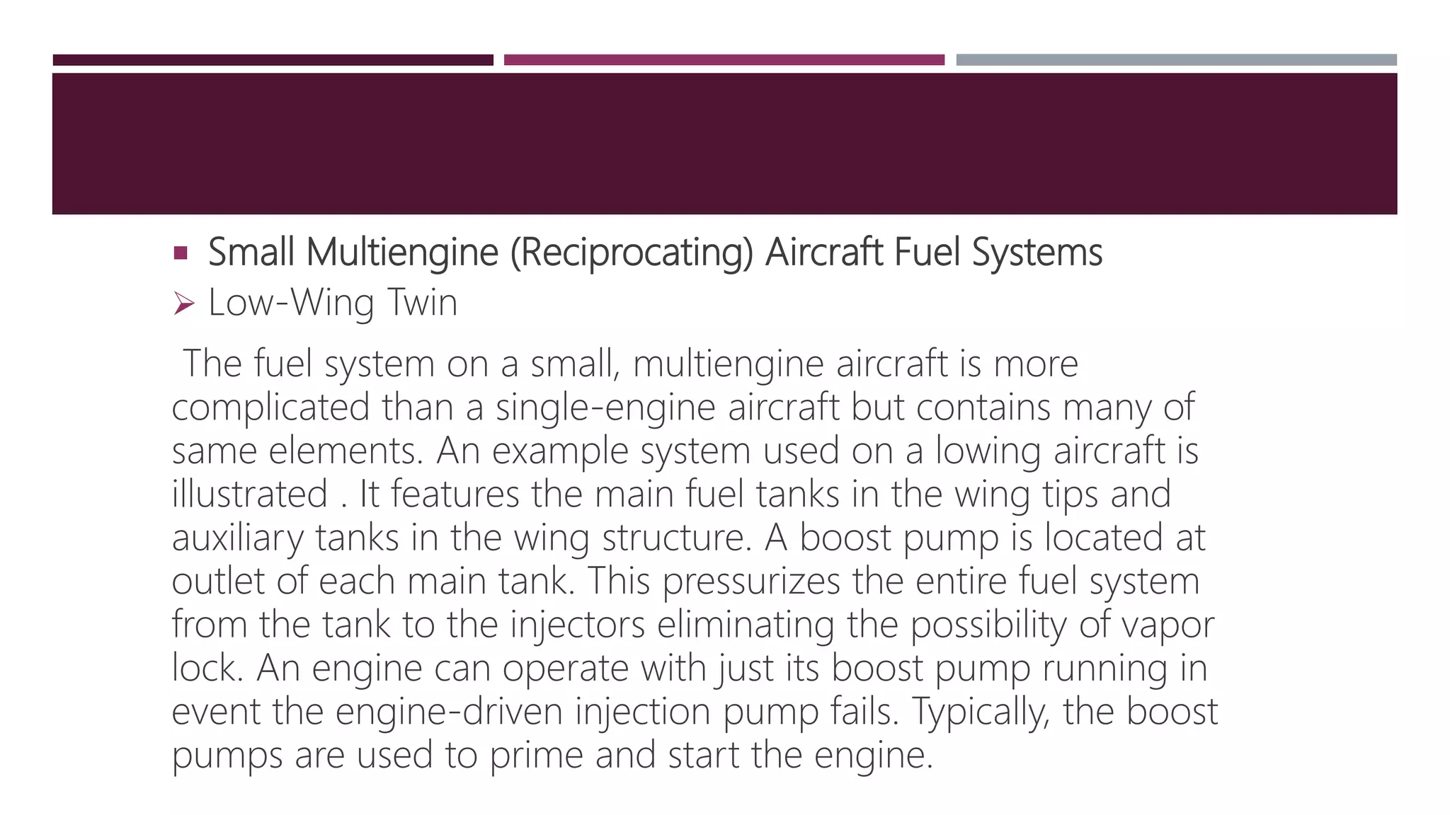
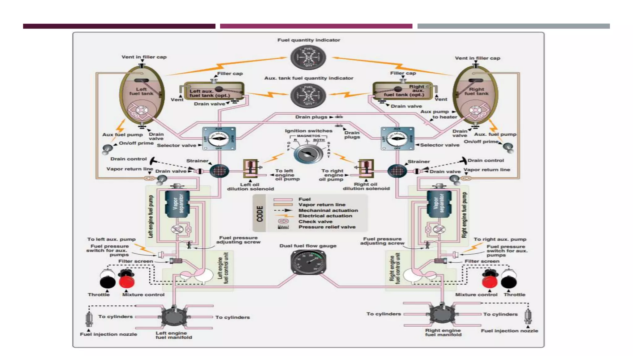
The fuel system on a small, multiengine aircraft is more
complicated than a single-engine aircraft but contains many of
same elements. An example system used on a lowing aircraft is
illustrated . It features the main fuel tanks in the wing tips and
auxiliary tanks in the wing structure. A boost pump is located at
outlet of each main tank. This pressurizes the entire fuel system
from the tank to the injectors eliminating the possibility of vapor
lock. An engine can operate with just its boost pump running in
event the engine-driven injection pump fails. Typically, the boost
pumps are used to prime and start the engine.
 High-Wing Twin
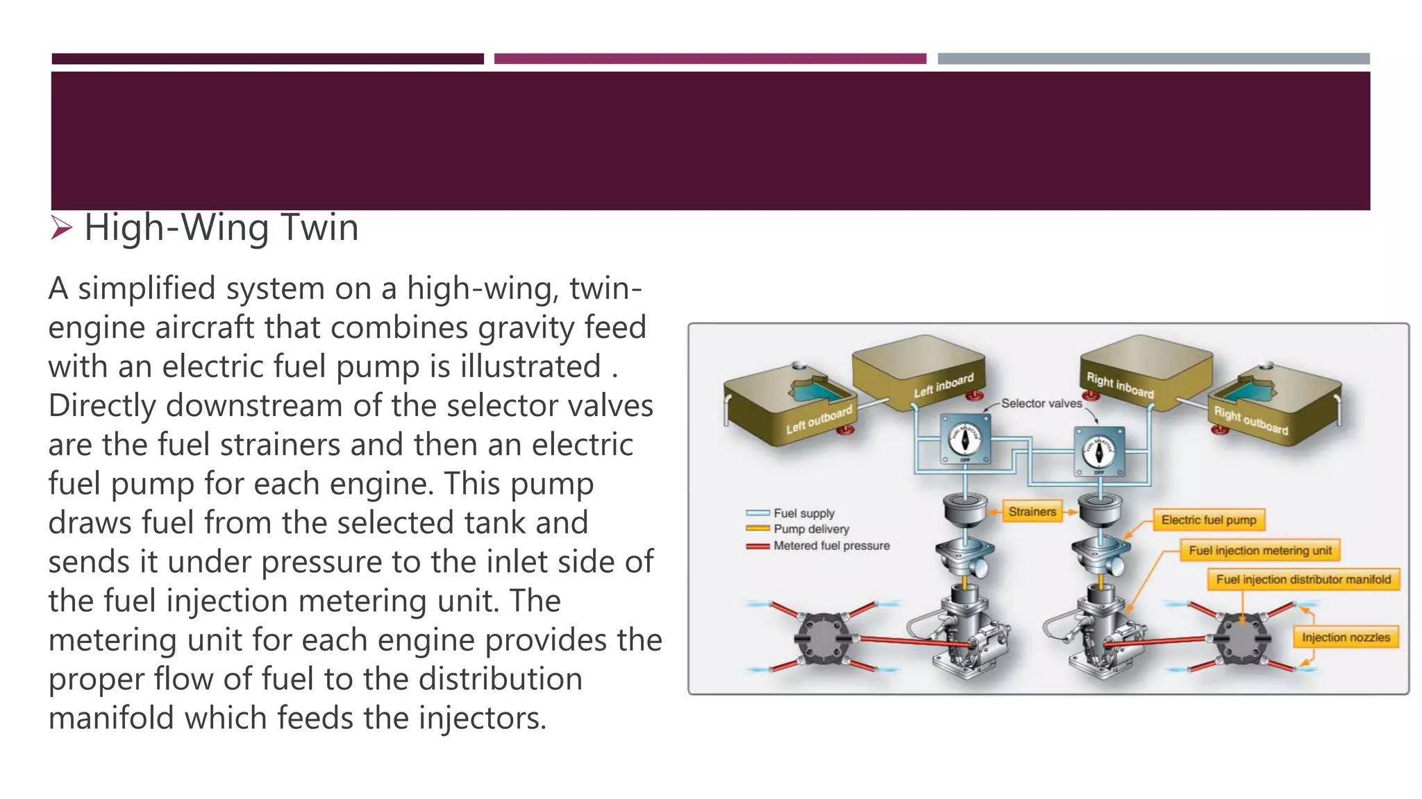
A simplified system on a high-wing, twin-
engine aircraft that combines gravity feed
with an electric fuel pump is illustrated .
Directly downstream of the selector valves
are the fuel strainers and then an electric
fuel pump for each engine. This pump
draws fuel from the selected tank and
sends it under pressure to the inlet side of
the fuel injection metering unit. The
metering unit for each engine provides the
proper flow of fuel to the distribution
manifold which feeds the injectors.
FUEL SYSTEM COMPONENTS
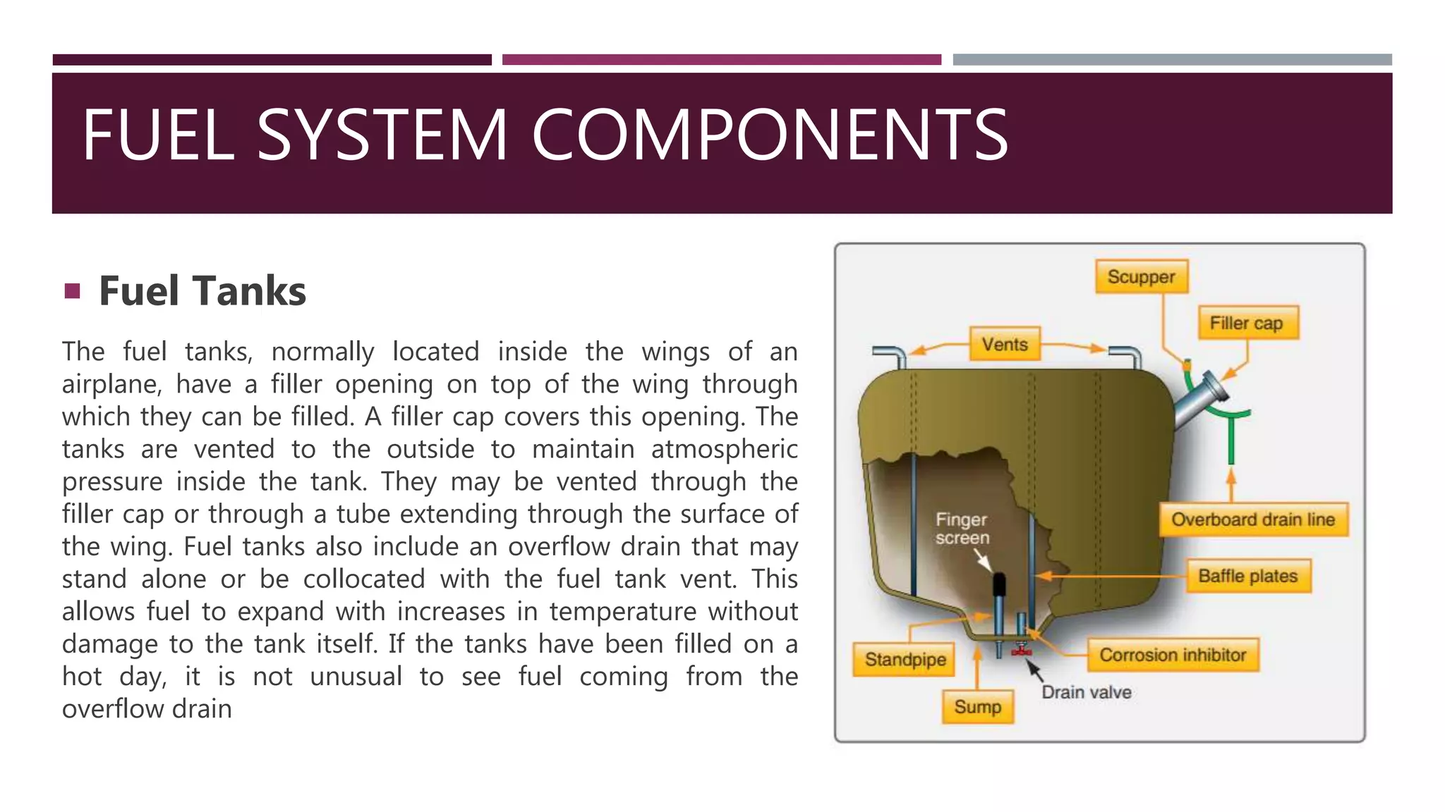
 Fuel Tanks
The fuel tanks, normally located inside the wings of an
airplane, have a filler opening on top of the wing through
which they can be filled. A filler cap covers this opening. The
tanks are vented to the outside to maintain atmospheric
pressure inside the tank. They may be vented through the
filler cap or through a tube extending through the surface of
the wing. Fuel tanks also include an overflow drain that may
stand alone or be collocated with the fuel tank vent. This
allows fuel to expand with increases in temperature without
damage to the tank itself. If the tanks have been filled on a
hot day, it is not unusual to see fuel coming from the
overflow drain
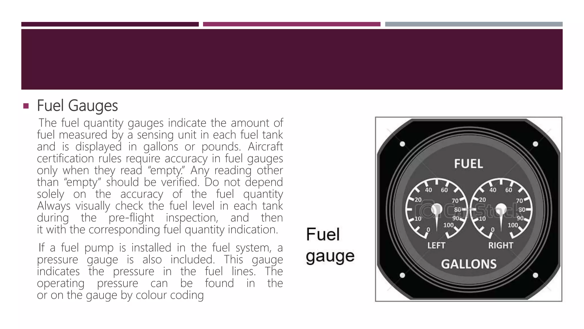
 Fuel Gauges
The fuel quantity gauges indicate the amount of
fuel measured by a sensing unit in each fuel tank
and is displayed in gallons or pounds. Aircraft
certification rules require accuracy in fuel gauges
only when they read “empty.” Any reading other
than “empty” should be verified. Do not depend
solely on the accuracy of the fuel quantity
Always visually check the fuel level in each tank
during the pre-flight inspection, and then
it with the corresponding fuel quantity indication.
If a fuel pump is installed in the fuel system, a
pressure gauge is also included. This gauge
indicates the pressure in the fuel lines. The
operating pressure can be found in the
or on the gauge by colour coding
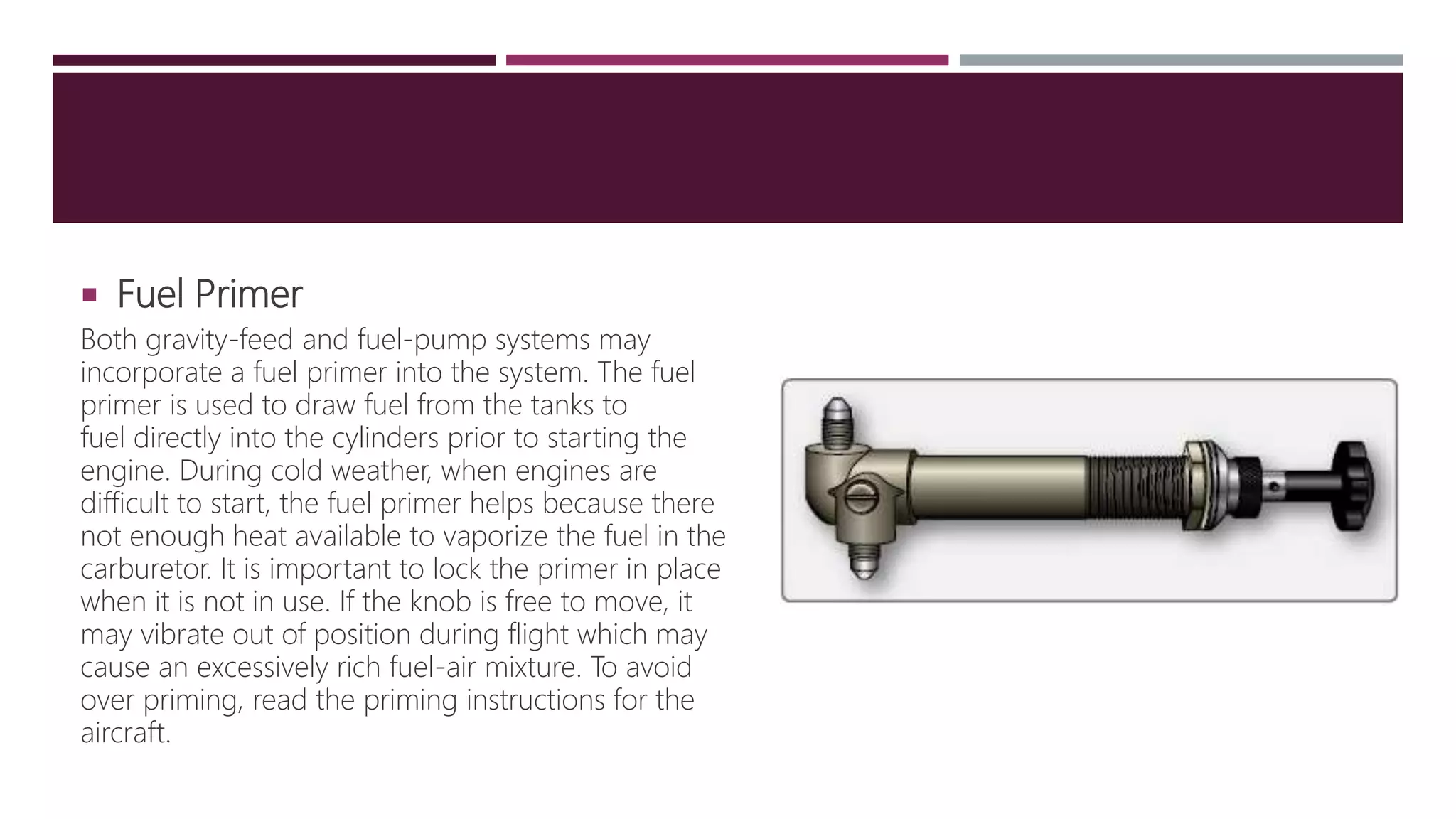
 Fuel Primer
Both gravity-feed and fuel-pump systems may
incorporate a fuel primer into the system. The fuel
primer is used to draw fuel from the tanks to
fuel directly into the cylinders prior to starting the
engine. During cold weather, when engines are
difficult to start, the fuel primer helps because there
not enough heat available to vaporize the fuel in the
carburetor. It is important to lock the primer in place
when it is not in use. If the knob is free to move, it
may vibrate out of position during flight which may
cause an excessively rich fuel-air mixture. To avoid
over priming, read the priming instructions for the
aircraft.
 Fuel Selectors
The fuel selector valve allows selection of fuel from
various tanks. A common type of selector valve
contains four positions: LEFT, RIGHT, BOTH, and OFF.
Selecting the LEFT or RIGHT position allows fuel to
feed only from the respective tank, while selecting
BOTH position feeds fuel from both tanks. The LEFT
or RIGHT position may be used to balance the
amount of fuel remaining in each wing tank.
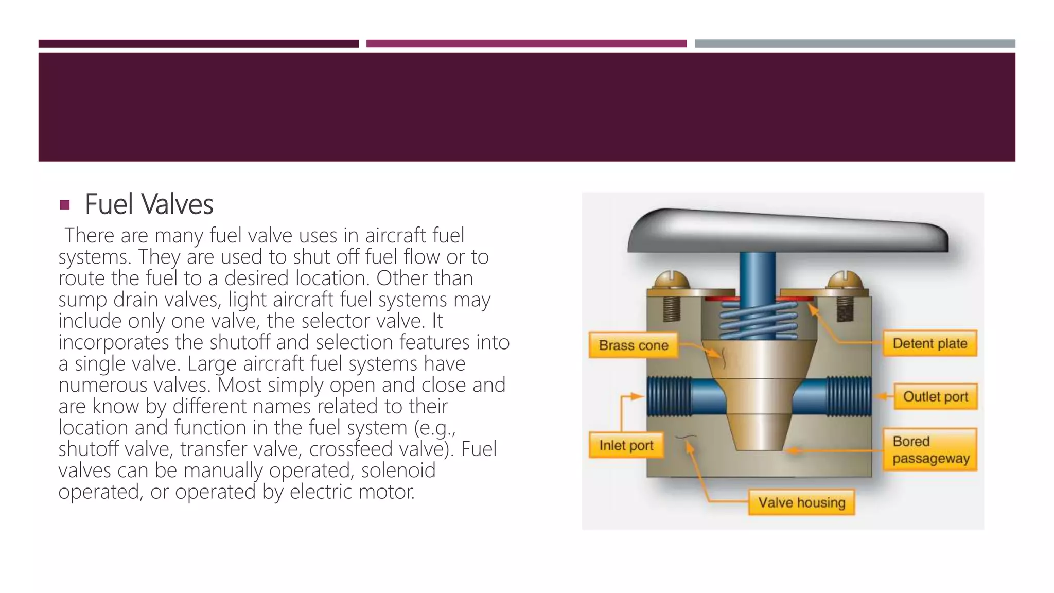
 Fuel Valves
There are many fuel valve uses in aircraft fuel
systems. They are used to shut off fuel flow or to
route the fuel to a desired location. Other than
sump drain valves, light aircraft fuel systems may
include only one valve, the selector valve. It
incorporates the shutoff and selection features into
a single valve. Large aircraft fuel systems have
numerous valves. Most simply open and close and
are know by different names related to their
location and function in the fuel system (e.g.,
shutoff valve, transfer valve, crossfeed valve). Fuel
valves can be manually operated, solenoid
operated, or operated by electric motor.
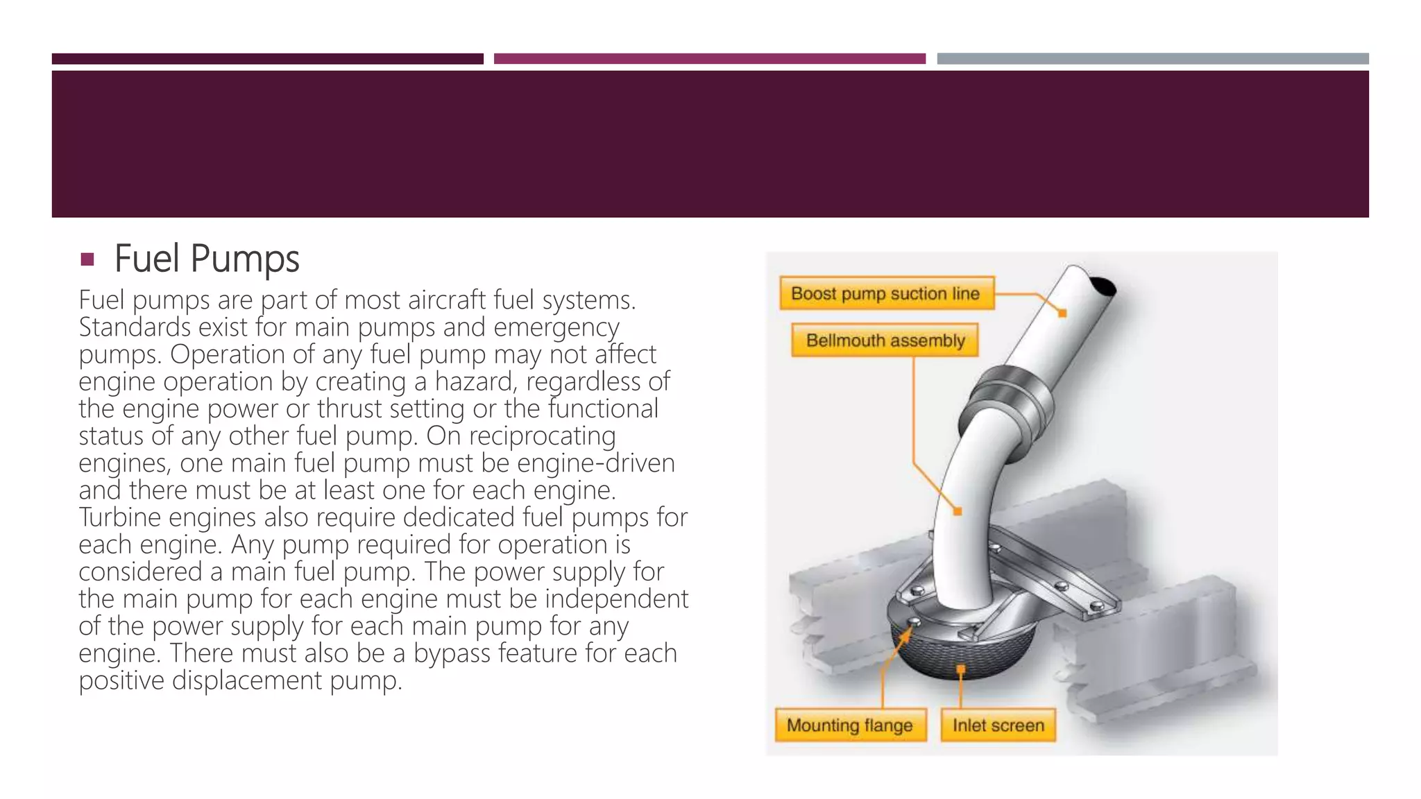
 Fuel Pumps
Fuel pumps are part of most aircraft fuel systems.
Standards exist for main pumps and emergency
pumps. Operation of any fuel pump may not affect
engine operation by creating a hazard, regardless of
the engine power or thrust setting or the functional
status of any other fuel pump. On reciprocating
engines, one main fuel pump must be engine-driven
and there must be at least one for each engine.
Turbine engines also require dedicated fuel pumps for
each engine. Any pump required for operation is
considered a main fuel pump. The power supply for
the main pump for each engine must be independent
of the power supply for each main pump for any
engine. There must also be a bypass feature for each
positive displacement pump.
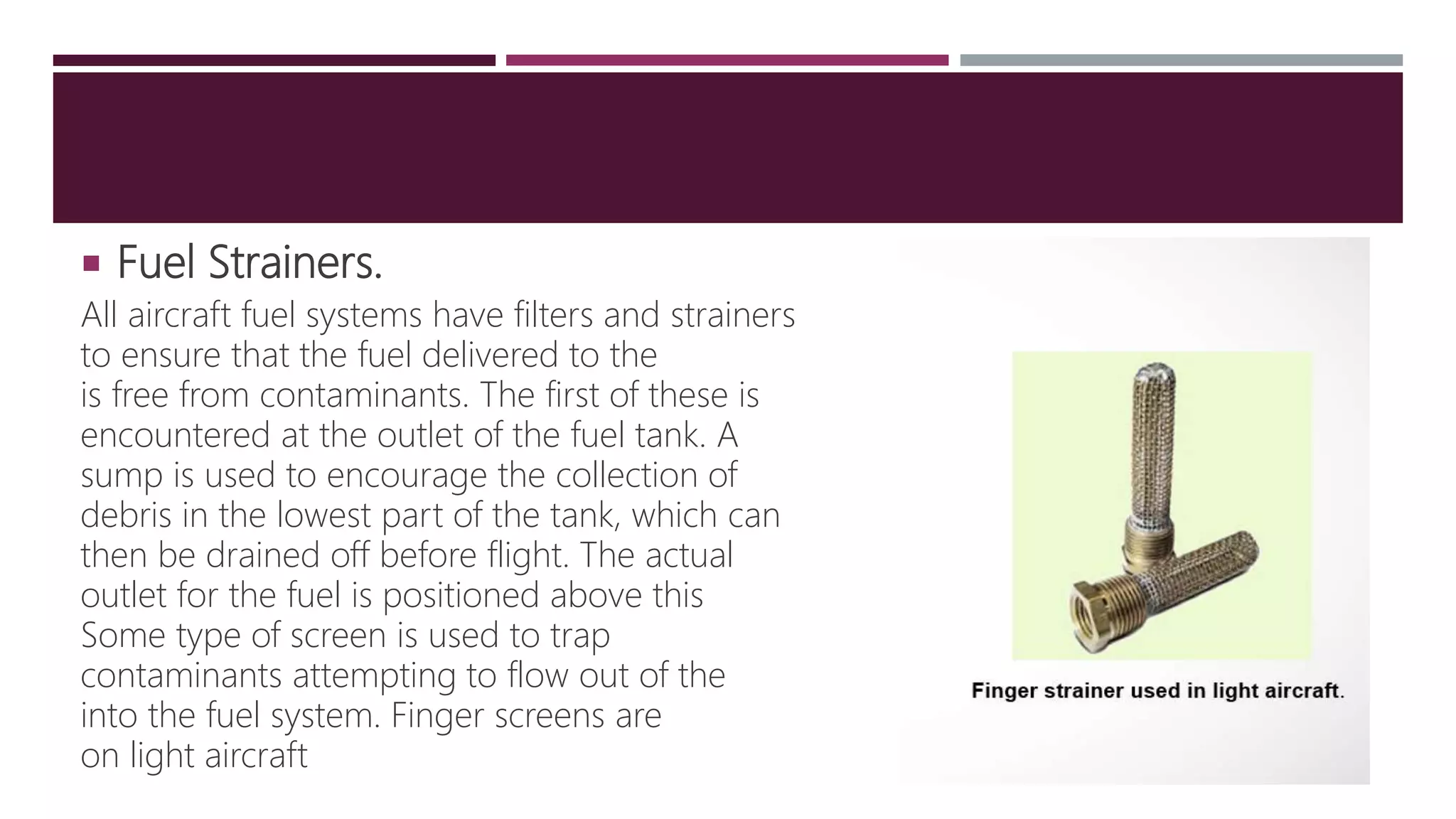
 Fuel Strainers.
All aircraft fuel systems have filters and strainers
to ensure that the fuel delivered to the
is free from contaminants. The first of these is
encountered at the outlet of the fuel tank. A
sump is used to encourage the collection of
debris in the lowest part of the tank, which can
then be drained off before flight. The actual
outlet for the fuel is positioned above this
Some type of screen is used to trap
contaminants attempting to flow out of the
into the fuel system. Finger screens are
on light aircraft
TYPES OF FUEL USED
 Conventional aviation fuels:
1.Jet fuel:is a clear to straw-colored fuel, based on either an unleaded kerosene (Jet A-1), or a
naphtha-kerosene blend (Jet B). Similar to diesel fuel, it can be used in either compression ignition
engines or turbine engines.
2.Avgas (aviation gasoline:is used by small aircraft, light helicopters and vintage piston-engined aircraft.
Its formulation is distinct from the conventional gasoline (petrol U.K.) used in motor vehicles which is
commonly called mogas or autogas in aviation context.
 Emerging aviation fuels:
1. Biofuels :Alternatives to conventional fossil-based aviation fuels, new fuels made via the biomass
to liquid method (like sustainable aviation fuel) and certain straight vegetable oils can also be
used.
2. Compressed natural gas (CNG) :are fuel feedstocks that aircraft may use in the future.
THANK YOU !

More Related Content

What's hot

Devices operated by hydraulic system in aircraft
Devices operated by hydraulic system in aircraft Devices operated by hydraulic system in aircraft
Devices operated by hydraulic system in aircraft
Mal Mai
 
Avionics Systems Instruments
Avionics Systems InstrumentsAvionics Systems Instruments
Avionics Systems InstrumentsMichael Bseliss
 
Piston engine powerplant
Piston engine powerplantPiston engine powerplant
Piston engine powerplantJohan Andhira
 
Aircraft wing
Aircraft wingAircraft wing
Aircraft wing
Thirumal Aero
 
How Gas Turbine Engine Works
How Gas Turbine Engine WorksHow Gas Turbine Engine Works
How Gas Turbine Engine Works
Indra Yudhipratama
 
Aircraft instruments
Aircraft instrumentsAircraft instruments
Aircraft instruments
Kamaraja AS
 
Hydraulic system of landing gear in Aircraft
Hydraulic system of landing gear in Aircraft Hydraulic system of landing gear in Aircraft
Hydraulic system of landing gear in Aircraft
Jordan Tractor and Equipment Co.
 
Aircraft oil systems
Aircraft oil systemsAircraft oil systems
Aircraft oil systems
MalcolmHarnden
 
Anti icingt4
Anti icingt4Anti icingt4
Anti icingt4
Jason Clark Alonto
 
Aircraft propulsion system
Aircraft propulsion systemAircraft propulsion system
Aircraft propulsion system
Deepak Vishwakarma
 
Aircraft Air Conditioning And Pressurisation System
Aircraft Air Conditioning And Pressurisation SystemAircraft Air Conditioning And Pressurisation System
Aircraft Air Conditioning And Pressurisation System
Cahit Kutay Uysal
 
Jet propulsion
Jet propulsionJet propulsion
Jet propulsion
vishal parmar
 
Aircraft Systems and Instruments
Aircraft Systems and InstrumentsAircraft Systems and Instruments
Aircraft Systems and Instruments
Varun Karthikeyan
 
Aircraft mechanical cable control system
Aircraft mechanical cable control systemAircraft mechanical cable control system
Aircraft mechanical cable control system
raj_sevak
 
Multi point fuel injection
Multi point fuel injectionMulti point fuel injection
Multi point fuel injection
RAVI KUMAR
 
Aviation Pneumatic Systems
 Aviation Pneumatic Systems  Aviation Pneumatic Systems
Aviation Pneumatic Systems cloisios
 
EASA PART 66 Module 15.10 : Lubrication Systems
EASA PART 66 Module 15.10 : Lubrication SystemsEASA PART 66 Module 15.10 : Lubrication Systems
EASA PART 66 Module 15.10 : Lubrication Systems
soulstalker
 
Gas turbine engine
Gas turbine engineGas turbine engine
Gas turbine engine
Uday Wankar
 

What's hot (20)

Devices operated by hydraulic system in aircraft
Devices operated by hydraulic system in aircraft Devices operated by hydraulic system in aircraft
Devices operated by hydraulic system in aircraft
 
Avionics Systems Instruments
Avionics Systems InstrumentsAvionics Systems Instruments
Avionics Systems Instruments
 
Piston engine powerplant
Piston engine powerplantPiston engine powerplant
Piston engine powerplant
 
Aircraft wing
Aircraft wingAircraft wing
Aircraft wing
 
How Gas Turbine Engine Works
How Gas Turbine Engine WorksHow Gas Turbine Engine Works
How Gas Turbine Engine Works
 
Aircraft instruments
Aircraft instrumentsAircraft instruments
Aircraft instruments
 
Hydraulic system of landing gear in Aircraft
Hydraulic system of landing gear in Aircraft Hydraulic system of landing gear in Aircraft
Hydraulic system of landing gear in Aircraft
 
Aircraft oil systems
Aircraft oil systemsAircraft oil systems
Aircraft oil systems
 
Anti icingt4
Anti icingt4Anti icingt4
Anti icingt4
 
Aircraft propulsion system
Aircraft propulsion systemAircraft propulsion system
Aircraft propulsion system
 
Aircraft Air Conditioning And Pressurisation System
Aircraft Air Conditioning And Pressurisation SystemAircraft Air Conditioning And Pressurisation System
Aircraft Air Conditioning And Pressurisation System
 
Aircraft fuel system
Aircraft fuel systemAircraft fuel system
Aircraft fuel system
 
Jet propulsion
Jet propulsionJet propulsion
Jet propulsion
 
Aircraft Systems and Instruments
Aircraft Systems and InstrumentsAircraft Systems and Instruments
Aircraft Systems and Instruments
 
Aircraft mechanical cable control system
Aircraft mechanical cable control systemAircraft mechanical cable control system
Aircraft mechanical cable control system
 
Multi point fuel injection
Multi point fuel injectionMulti point fuel injection
Multi point fuel injection
 
Aviation Pneumatic Systems
 Aviation Pneumatic Systems  Aviation Pneumatic Systems
Aviation Pneumatic Systems
 
EASA PART 66 Module 15.10 : Lubrication Systems
EASA PART 66 Module 15.10 : Lubrication SystemsEASA PART 66 Module 15.10 : Lubrication Systems
EASA PART 66 Module 15.10 : Lubrication Systems
 
our project
our projectour project
our project
 
Gas turbine engine
Gas turbine engineGas turbine engine
Gas turbine engine
 

Similar to Aircraft Fuel System

Aero engine systems and instruments AVA 1
Aero engine systems and instruments AVA 1Aero engine systems and instruments AVA 1
Aero engine systems and instruments AVA 1
oldcramo2009
 
Fuel Systems
Fuel SystemsFuel Systems
Fuel Systems
Ramkiran Lepakshi
 
3-191221152949. fuel system presentation
3-191221152949. fuel system presentation3-191221152949. fuel system presentation
3-191221152949. fuel system presentation
manishanageshrai27
 
Fuel feed system for petrol engine
Fuel feed system for petrol engineFuel feed system for petrol engine
Fuel feed system for petrol engine
SwapnilDahake2
 
Unit 2.pdf
Unit 2.pdfUnit 2.pdf
Unit 2.pdf
anilakumara
 
Aero engine accessories
Aero engine accessoriesAero engine accessories
Aero engine accessories
Abhishek Alankar
 
Automobile unit 2 Engine Auxiliary Systems
Automobile unit 2   Engine Auxiliary SystemsAutomobile unit 2   Engine Auxiliary Systems
Automobile unit 2 Engine Auxiliary Systems
RMK College of Engineering and Technology
 
Fuel feed system in petrol engine ppt
Fuel feed system in petrol engine pptFuel feed system in petrol engine ppt
Fuel feed system in petrol engine ppt
jagadeeskumar govindan
 
Review of Aircraft Fuel System
Review of Aircraft Fuel SystemReview of Aircraft Fuel System
Review of Aircraft Fuel System
IJARIIE JOURNAL
 
Fuel Dispensing Technology
Fuel Dispensing TechnologyFuel Dispensing Technology
Fuel Dispensing Technology
Emmanuel Danso
 
SIAUT_Fuel_Injection_Systems-Gasoline.pdf
SIAUT_Fuel_Injection_Systems-Gasoline.pdfSIAUT_Fuel_Injection_Systems-Gasoline.pdf
SIAUT_Fuel_Injection_Systems-Gasoline.pdf
Keerthi914725
 
AIRFRAME SYSTEMS.pptx
AIRFRAME SYSTEMS.pptxAIRFRAME SYSTEMS.pptx
AIRFRAME SYSTEMS.pptx
VickyVignesh409360
 
Multipoint Fuel Injection System (MPFI)
Multipoint Fuel Injection System (MPFI)Multipoint Fuel Injection System (MPFI)
Multipoint Fuel Injection System (MPFI)
Rutwij Patil
 
THIS PPT ON ELECTRONIC FUEL INJECTION SYSTEM
THIS PPT ON ELECTRONIC FUEL INJECTION SYSTEMTHIS PPT ON ELECTRONIC FUEL INJECTION SYSTEM
THIS PPT ON ELECTRONIC FUEL INJECTION SYSTEM
sanjay kumar pediredla
 
Electronic Fuel Injection System
Electronic Fuel Injection SystemElectronic Fuel Injection System
Electronic Fuel Injection System
John Alexis
 
B737 NG Fuel System.
B737 NG Fuel System.B737 NG Fuel System.
B737 NG Fuel System.
theoryce
 
Marine Diesel Engine main Systemss.pptx
Marine Diesel Engine  main Systemss.pptxMarine Diesel Engine  main Systemss.pptx
Marine Diesel Engine main Systemss.pptx
elimunyao
 
Multipointfuelinjectionsystem 150310112043-conversion-gate012-160424070702 (1)
Multipointfuelinjectionsystem 150310112043-conversion-gate012-160424070702 (1)Multipointfuelinjectionsystem 150310112043-conversion-gate012-160424070702 (1)
Multipointfuelinjectionsystem 150310112043-conversion-gate012-160424070702 (1)
udit19968
 
UNIT-II-ENGINE AUXILIARY SYSTEMS &TURBOCHARGER
UNIT-II-ENGINE AUXILIARY SYSTEMS &TURBOCHARGERUNIT-II-ENGINE AUXILIARY SYSTEMS &TURBOCHARGER
UNIT-II-ENGINE AUXILIARY SYSTEMS &TURBOCHARGER
DineshKumar4165
 
AUTOMOBILE ENGINEERING
AUTOMOBILE ENGINEERINGAUTOMOBILE ENGINEERING
AUTOMOBILE ENGINEERING
Dr.S.SURESH
 

Similar to Aircraft Fuel System (20)

Aero engine systems and instruments AVA 1
Aero engine systems and instruments AVA 1Aero engine systems and instruments AVA 1
Aero engine systems and instruments AVA 1
 
Fuel Systems
Fuel SystemsFuel Systems
Fuel Systems
 
3-191221152949. fuel system presentation
3-191221152949. fuel system presentation3-191221152949. fuel system presentation
3-191221152949. fuel system presentation
 
Fuel feed system for petrol engine
Fuel feed system for petrol engineFuel feed system for petrol engine
Fuel feed system for petrol engine
 
Unit 2.pdf
Unit 2.pdfUnit 2.pdf
Unit 2.pdf
 
Aero engine accessories
Aero engine accessoriesAero engine accessories
Aero engine accessories
 
Automobile unit 2 Engine Auxiliary Systems
Automobile unit 2   Engine Auxiliary SystemsAutomobile unit 2   Engine Auxiliary Systems
Automobile unit 2 Engine Auxiliary Systems
 
Fuel feed system in petrol engine ppt
Fuel feed system in petrol engine pptFuel feed system in petrol engine ppt
Fuel feed system in petrol engine ppt
 
Review of Aircraft Fuel System
Review of Aircraft Fuel SystemReview of Aircraft Fuel System
Review of Aircraft Fuel System
 
Fuel Dispensing Technology
Fuel Dispensing TechnologyFuel Dispensing Technology
Fuel Dispensing Technology
 
SIAUT_Fuel_Injection_Systems-Gasoline.pdf
SIAUT_Fuel_Injection_Systems-Gasoline.pdfSIAUT_Fuel_Injection_Systems-Gasoline.pdf
SIAUT_Fuel_Injection_Systems-Gasoline.pdf
 
AIRFRAME SYSTEMS.pptx
AIRFRAME SYSTEMS.pptxAIRFRAME SYSTEMS.pptx
AIRFRAME SYSTEMS.pptx
 
Multipoint Fuel Injection System (MPFI)
Multipoint Fuel Injection System (MPFI)Multipoint Fuel Injection System (MPFI)
Multipoint Fuel Injection System (MPFI)
 
THIS PPT ON ELECTRONIC FUEL INJECTION SYSTEM
THIS PPT ON ELECTRONIC FUEL INJECTION SYSTEMTHIS PPT ON ELECTRONIC FUEL INJECTION SYSTEM
THIS PPT ON ELECTRONIC FUEL INJECTION SYSTEM
 
Electronic Fuel Injection System
Electronic Fuel Injection SystemElectronic Fuel Injection System
Electronic Fuel Injection System
 
B737 NG Fuel System.
B737 NG Fuel System.B737 NG Fuel System.
B737 NG Fuel System.
 
Marine Diesel Engine main Systemss.pptx
Marine Diesel Engine  main Systemss.pptxMarine Diesel Engine  main Systemss.pptx
Marine Diesel Engine main Systemss.pptx
 
Multipointfuelinjectionsystem 150310112043-conversion-gate012-160424070702 (1)
Multipointfuelinjectionsystem 150310112043-conversion-gate012-160424070702 (1)Multipointfuelinjectionsystem 150310112043-conversion-gate012-160424070702 (1)
Multipointfuelinjectionsystem 150310112043-conversion-gate012-160424070702 (1)
 
UNIT-II-ENGINE AUXILIARY SYSTEMS &TURBOCHARGER
UNIT-II-ENGINE AUXILIARY SYSTEMS &TURBOCHARGERUNIT-II-ENGINE AUXILIARY SYSTEMS &TURBOCHARGER
UNIT-II-ENGINE AUXILIARY SYSTEMS &TURBOCHARGER
 
AUTOMOBILE ENGINEERING
AUTOMOBILE ENGINEERINGAUTOMOBILE ENGINEERING
AUTOMOBILE ENGINEERING
 

Recently uploaded

The Role of Electrical and Electronics Engineers in IOT Technology.pdf
The Role of Electrical and Electronics Engineers in IOT Technology.pdfThe Role of Electrical and Electronics Engineers in IOT Technology.pdf
The Role of Electrical and Electronics Engineers in IOT Technology.pdf
Nettur Technical Training Foundation
 
Student information management system project report ii.pdf
Student information management system project report ii.pdfStudent information management system project report ii.pdf
Student information management system project report ii.pdf
Kamal Acharya
 
Cosmetic shop management system project report.pdf
Cosmetic shop management system project report.pdfCosmetic shop management system project report.pdf
Cosmetic shop management system project report.pdf
Kamal Acharya
 
Governing Equations for Fundamental Aerodynamics_Anderson2010.pdf
Governing Equations for Fundamental Aerodynamics_Anderson2010.pdfGoverning Equations for Fundamental Aerodynamics_Anderson2010.pdf
Governing Equations for Fundamental Aerodynamics_Anderson2010.pdf
WENKENLI1
 
Basic Industrial Engineering terms for apparel
Basic Industrial Engineering terms for apparelBasic Industrial Engineering terms for apparel
Basic Industrial Engineering terms for apparel
top1002
 
Heap Sort (SS).ppt FOR ENGINEERING GRADUATES, BCA, MCA, MTECH, BSC STUDENTS
Heap Sort (SS).ppt FOR ENGINEERING GRADUATES, BCA, MCA, MTECH, BSC STUDENTSHeap Sort (SS).ppt FOR ENGINEERING GRADUATES, BCA, MCA, MTECH, BSC STUDENTS
Heap Sort (SS).ppt FOR ENGINEERING GRADUATES, BCA, MCA, MTECH, BSC STUDENTS
Soumen Santra
 
DESIGN AND ANALYSIS OF A CAR SHOWROOM USING E TABS
DESIGN AND ANALYSIS OF A CAR SHOWROOM USING E TABSDESIGN AND ANALYSIS OF A CAR SHOWROOM USING E TABS
DESIGN AND ANALYSIS OF A CAR SHOWROOM USING E TABS
itech2017
 
14 Template Contractual Notice - EOT Application
14 Template Contractual Notice - EOT Application14 Template Contractual Notice - EOT Application
14 Template Contractual Notice - EOT Application
SyedAbiiAzazi1
 
Planning Of Procurement o different goods and services
Planning Of Procurement o different goods and servicesPlanning Of Procurement o different goods and services
Planning Of Procurement o different goods and services
JoytuBarua2
 
Steel & Timber Design according to British Standard
Steel & Timber Design according to British StandardSteel & Timber Design according to British Standard
Steel & Timber Design according to British Standard
AkolbilaEmmanuel1
 
DfMAy 2024 - key insights and contributions
DfMAy 2024 - key insights and contributionsDfMAy 2024 - key insights and contributions
DfMAy 2024 - key insights and contributions
gestioneergodomus
 
一比一原版(IIT毕业证)伊利诺伊理工大学毕业证成绩单专业办理
一比一原版(IIT毕业证)伊利诺伊理工大学毕业证成绩单专业办理一比一原版(IIT毕业证)伊利诺伊理工大学毕业证成绩单专业办理
一比一原版(IIT毕业证)伊利诺伊理工大学毕业证成绩单专业办理
zwunae
 
road safety engineering r s e unit 3.pdf
road safety engineering  r s e unit 3.pdfroad safety engineering  r s e unit 3.pdf
road safety engineering r s e unit 3.pdf
VENKATESHvenky89705
 
Investor-Presentation-Q1FY2024 investor presentation document.pptx
Investor-Presentation-Q1FY2024 investor presentation document.pptxInvestor-Presentation-Q1FY2024 investor presentation document.pptx
Investor-Presentation-Q1FY2024 investor presentation document.pptx
AmarGB2
 
Fundamentals of Electric Drives and its applications.pptx
Fundamentals of Electric Drives and its applications.pptxFundamentals of Electric Drives and its applications.pptx
Fundamentals of Electric Drives and its applications.pptx
manasideore6
 
Gen AI Study Jams _ For the GDSC Leads in India.pdf
Gen AI Study Jams _ For the GDSC Leads in India.pdfGen AI Study Jams _ For the GDSC Leads in India.pdf
Gen AI Study Jams _ For the GDSC Leads in India.pdf
gdsczhcet
 
AKS UNIVERSITY Satna Final Year Project By OM Hardaha.pdf
AKS UNIVERSITY Satna Final Year Project By OM Hardaha.pdfAKS UNIVERSITY Satna Final Year Project By OM Hardaha.pdf
AKS UNIVERSITY Satna Final Year Project By OM Hardaha.pdf
SamSarthak3
 
Harnessing WebAssembly for Real-time Stateless Streaming Pipelines
Harnessing WebAssembly for Real-time Stateless Streaming PipelinesHarnessing WebAssembly for Real-time Stateless Streaming Pipelines
Harnessing WebAssembly for Real-time Stateless Streaming Pipelines
Christina Lin
 
MCQ Soil mechanics questions (Soil shear strength).pdf
MCQ Soil mechanics questions (Soil shear strength).pdfMCQ Soil mechanics questions (Soil shear strength).pdf
MCQ Soil mechanics questions (Soil shear strength).pdf
Osamah Alsalih
 
Forklift Classes Overview by Intella Parts
Forklift Classes Overview by Intella PartsForklift Classes Overview by Intella Parts
Forklift Classes Overview by Intella Parts
Intella Parts
 

Recently uploaded (20)

The Role of Electrical and Electronics Engineers in IOT Technology.pdf
The Role of Electrical and Electronics Engineers in IOT Technology.pdfThe Role of Electrical and Electronics Engineers in IOT Technology.pdf
The Role of Electrical and Electronics Engineers in IOT Technology.pdf
 
Student information management system project report ii.pdf
Student information management system project report ii.pdfStudent information management system project report ii.pdf
Student information management system project report ii.pdf
 
Cosmetic shop management system project report.pdf
Cosmetic shop management system project report.pdfCosmetic shop management system project report.pdf
Cosmetic shop management system project report.pdf
 
Governing Equations for Fundamental Aerodynamics_Anderson2010.pdf
Governing Equations for Fundamental Aerodynamics_Anderson2010.pdfGoverning Equations for Fundamental Aerodynamics_Anderson2010.pdf
Governing Equations for Fundamental Aerodynamics_Anderson2010.pdf
 
Basic Industrial Engineering terms for apparel
Basic Industrial Engineering terms for apparelBasic Industrial Engineering terms for apparel
Basic Industrial Engineering terms for apparel
 
Heap Sort (SS).ppt FOR ENGINEERING GRADUATES, BCA, MCA, MTECH, BSC STUDENTS
Heap Sort (SS).ppt FOR ENGINEERING GRADUATES, BCA, MCA, MTECH, BSC STUDENTSHeap Sort (SS).ppt FOR ENGINEERING GRADUATES, BCA, MCA, MTECH, BSC STUDENTS
Heap Sort (SS).ppt FOR ENGINEERING GRADUATES, BCA, MCA, MTECH, BSC STUDENTS
 
DESIGN AND ANALYSIS OF A CAR SHOWROOM USING E TABS
DESIGN AND ANALYSIS OF A CAR SHOWROOM USING E TABSDESIGN AND ANALYSIS OF A CAR SHOWROOM USING E TABS
DESIGN AND ANALYSIS OF A CAR SHOWROOM USING E TABS
 
14 Template Contractual Notice - EOT Application
14 Template Contractual Notice - EOT Application14 Template Contractual Notice - EOT Application
14 Template Contractual Notice - EOT Application
 
Planning Of Procurement o different goods and services
Planning Of Procurement o different goods and servicesPlanning Of Procurement o different goods and services
Planning Of Procurement o different goods and services
 
Steel & Timber Design according to British Standard
Steel & Timber Design according to British StandardSteel & Timber Design according to British Standard
Steel & Timber Design according to British Standard
 
DfMAy 2024 - key insights and contributions
DfMAy 2024 - key insights and contributionsDfMAy 2024 - key insights and contributions
DfMAy 2024 - key insights and contributions
 
一比一原版(IIT毕业证)伊利诺伊理工大学毕业证成绩单专业办理
一比一原版(IIT毕业证)伊利诺伊理工大学毕业证成绩单专业办理一比一原版(IIT毕业证)伊利诺伊理工大学毕业证成绩单专业办理
一比一原版(IIT毕业证)伊利诺伊理工大学毕业证成绩单专业办理
 
road safety engineering r s e unit 3.pdf
road safety engineering  r s e unit 3.pdfroad safety engineering  r s e unit 3.pdf
road safety engineering r s e unit 3.pdf
 
Investor-Presentation-Q1FY2024 investor presentation document.pptx
Investor-Presentation-Q1FY2024 investor presentation document.pptxInvestor-Presentation-Q1FY2024 investor presentation document.pptx
Investor-Presentation-Q1FY2024 investor presentation document.pptx
 
Fundamentals of Electric Drives and its applications.pptx
Fundamentals of Electric Drives and its applications.pptxFundamentals of Electric Drives and its applications.pptx
Fundamentals of Electric Drives and its applications.pptx
 
Gen AI Study Jams _ For the GDSC Leads in India.pdf
Gen AI Study Jams _ For the GDSC Leads in India.pdfGen AI Study Jams _ For the GDSC Leads in India.pdf
Gen AI Study Jams _ For the GDSC Leads in India.pdf
 
AKS UNIVERSITY Satna Final Year Project By OM Hardaha.pdf
AKS UNIVERSITY Satna Final Year Project By OM Hardaha.pdfAKS UNIVERSITY Satna Final Year Project By OM Hardaha.pdf
AKS UNIVERSITY Satna Final Year Project By OM Hardaha.pdf
 
Harnessing WebAssembly for Real-time Stateless Streaming Pipelines
Harnessing WebAssembly for Real-time Stateless Streaming PipelinesHarnessing WebAssembly for Real-time Stateless Streaming Pipelines
Harnessing WebAssembly for Real-time Stateless Streaming Pipelines
 
MCQ Soil mechanics questions (Soil shear strength).pdf
MCQ Soil mechanics questions (Soil shear strength).pdfMCQ Soil mechanics questions (Soil shear strength).pdf
MCQ Soil mechanics questions (Soil shear strength).pdf
 
Forklift Classes Overview by Intella Parts
Forklift Classes Overview by Intella PartsForklift Classes Overview by Intella Parts
Forklift Classes Overview by Intella Parts
 

Aircraft Fuel System

  • 2. CONTENT  Description of Fuel System  Different types of Fuel System  Fuel System Components  Types of fuel used
  • 3. DESCRIPTION OF FUEL SYSTEM The fuel system is designed to provide an uninterrupted flow of clean fuel from the fuel tanks to the engine. The fuel must be available to the engine under all conditions of engine power, altitude, attitude, and during all approved flight maneuvers . Fuel systems differ greatly from aircraft to aircraft due to the relative size and complexity of the aircraft in which they are installed. In the most basic form. a fuel system will consist of a single, gravity feed fuel tank with the associated fuel line connecting it to the aircraft engine.
  • 4. DIFFERENT TYPES OF FUEL SYSTEM  Small Single-Engine Aircraft Fuel Systems  Gravity-Feed System - The gravity-feed system utilizes the force of gravity to transfer the fuel from the tanks to the engine. For example, on high-wing airplanes, the fuel tanks are installed in the wings. This places the fuel tanks above the carburettor, and the fuel is gravity fed through the system and into the carburettor. If the design of the aircraft is such that gravity cannot be used to transfer fuel, fuel pumps are installed. For example, on low-wing airplanes, the fuel tanks in the wings are located below the carburettor.
  • 5.  Fuel-Pump System - Aircraft with fuel-pump systems have two fuel pumps. The main pump system is engine driven with an electrically driven auxiliary pump provided for use in engine starting and in the event the engine pump fails. The auxiliary pump, also known as a boost pump, provides added reliability to the fuel system. The electrically-driven auxiliary pump is controlled by a switch in the flight deck.
  • 6.  Large Reciprocating-Engine Aircraft Fuel Systems Large, multiengine transport aircraft powered by reciprocating radial engines are no longer However, many are still in operation. A selector valve for each engine allows an engine-driven to pull fuel from the main tank or an auxiliary tank. The fuel passes through a strainer before the pump where it is delivered to the engine. The outlet of the pump can feed either engine the use of a crossfeed line with valves controlled in the cockpit. A hand-operated wobble pump located upstream of the strainer is used to prime the system for starting. Fuel vapor lines run from pressure carburetor to the vent space in the main and auxiliary tanks. Fuel pressure gauges are off of the carburetor for power indication. The hand-operated wobble pumps were replaced by electric pumps on later model aircraft. A fuel pressure warning light tapped in downstream of the engine-driven fuel pump alerts the crew fuel pressure decline.
  • 7.
  • 8.  Small Multiengine (Reciprocating) Aircraft Fuel Systems  Low-Wing Twin The fuel system on a small, multiengine aircraft is more complicated than a single-engine aircraft but contains many of same elements. An example system used on a lowing aircraft is illustrated . It features the main fuel tanks in the wing tips and auxiliary tanks in the wing structure. A boost pump is located at outlet of each main tank. This pressurizes the entire fuel system from the tank to the injectors eliminating the possibility of vapor lock. An engine can operate with just its boost pump running in event the engine-driven injection pump fails. Typically, the boost pumps are used to prime and start the engine.
  • 9.
  • 10.  High-Wing Twin A simplified system on a high-wing, twin- engine aircraft that combines gravity feed with an electric fuel pump is illustrated . Directly downstream of the selector valves are the fuel strainers and then an electric fuel pump for each engine. This pump draws fuel from the selected tank and sends it under pressure to the inlet side of the fuel injection metering unit. The metering unit for each engine provides the proper flow of fuel to the distribution manifold which feeds the injectors.
  • 11. FUEL SYSTEM COMPONENTS  Fuel Tanks The fuel tanks, normally located inside the wings of an airplane, have a filler opening on top of the wing through which they can be filled. A filler cap covers this opening. The tanks are vented to the outside to maintain atmospheric pressure inside the tank. They may be vented through the filler cap or through a tube extending through the surface of the wing. Fuel tanks also include an overflow drain that may stand alone or be collocated with the fuel tank vent. This allows fuel to expand with increases in temperature without damage to the tank itself. If the tanks have been filled on a hot day, it is not unusual to see fuel coming from the overflow drain
  • 12.  Fuel Gauges The fuel quantity gauges indicate the amount of fuel measured by a sensing unit in each fuel tank and is displayed in gallons or pounds. Aircraft certification rules require accuracy in fuel gauges only when they read “empty.” Any reading other than “empty” should be verified. Do not depend solely on the accuracy of the fuel quantity Always visually check the fuel level in each tank during the pre-flight inspection, and then it with the corresponding fuel quantity indication. If a fuel pump is installed in the fuel system, a pressure gauge is also included. This gauge indicates the pressure in the fuel lines. The operating pressure can be found in the or on the gauge by colour coding
  • 13.  Fuel Primer Both gravity-feed and fuel-pump systems may incorporate a fuel primer into the system. The fuel primer is used to draw fuel from the tanks to fuel directly into the cylinders prior to starting the engine. During cold weather, when engines are difficult to start, the fuel primer helps because there not enough heat available to vaporize the fuel in the carburetor. It is important to lock the primer in place when it is not in use. If the knob is free to move, it may vibrate out of position during flight which may cause an excessively rich fuel-air mixture. To avoid over priming, read the priming instructions for the aircraft.
  • 14.  Fuel Selectors The fuel selector valve allows selection of fuel from various tanks. A common type of selector valve contains four positions: LEFT, RIGHT, BOTH, and OFF. Selecting the LEFT or RIGHT position allows fuel to feed only from the respective tank, while selecting BOTH position feeds fuel from both tanks. The LEFT or RIGHT position may be used to balance the amount of fuel remaining in each wing tank.
  • 15.  Fuel Valves There are many fuel valve uses in aircraft fuel systems. They are used to shut off fuel flow or to route the fuel to a desired location. Other than sump drain valves, light aircraft fuel systems may include only one valve, the selector valve. It incorporates the shutoff and selection features into a single valve. Large aircraft fuel systems have numerous valves. Most simply open and close and are know by different names related to their location and function in the fuel system (e.g., shutoff valve, transfer valve, crossfeed valve). Fuel valves can be manually operated, solenoid operated, or operated by electric motor.
  • 16.  Fuel Pumps Fuel pumps are part of most aircraft fuel systems. Standards exist for main pumps and emergency pumps. Operation of any fuel pump may not affect engine operation by creating a hazard, regardless of the engine power or thrust setting or the functional status of any other fuel pump. On reciprocating engines, one main fuel pump must be engine-driven and there must be at least one for each engine. Turbine engines also require dedicated fuel pumps for each engine. Any pump required for operation is considered a main fuel pump. The power supply for the main pump for each engine must be independent of the power supply for each main pump for any engine. There must also be a bypass feature for each positive displacement pump.
  • 17.  Fuel Strainers. All aircraft fuel systems have filters and strainers to ensure that the fuel delivered to the is free from contaminants. The first of these is encountered at the outlet of the fuel tank. A sump is used to encourage the collection of debris in the lowest part of the tank, which can then be drained off before flight. The actual outlet for the fuel is positioned above this Some type of screen is used to trap contaminants attempting to flow out of the into the fuel system. Finger screens are on light aircraft
  • 18. TYPES OF FUEL USED  Conventional aviation fuels: 1.Jet fuel:is a clear to straw-colored fuel, based on either an unleaded kerosene (Jet A-1), or a naphtha-kerosene blend (Jet B). Similar to diesel fuel, it can be used in either compression ignition engines or turbine engines. 2.Avgas (aviation gasoline:is used by small aircraft, light helicopters and vintage piston-engined aircraft. Its formulation is distinct from the conventional gasoline (petrol U.K.) used in motor vehicles which is commonly called mogas or autogas in aviation context.  Emerging aviation fuels: 1. Biofuels :Alternatives to conventional fossil-based aviation fuels, new fuels made via the biomass to liquid method (like sustainable aviation fuel) and certain straight vegetable oils can also be used. 2. Compressed natural gas (CNG) :are fuel feedstocks that aircraft may use in the future.