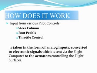
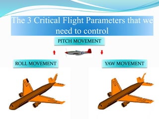
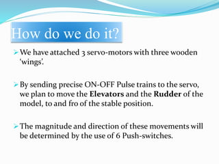
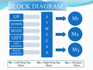
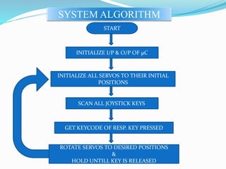
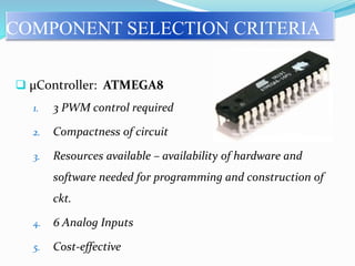
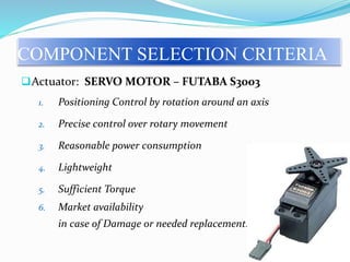
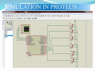
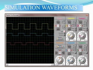
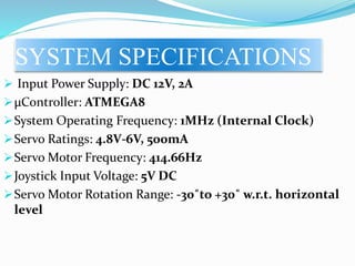
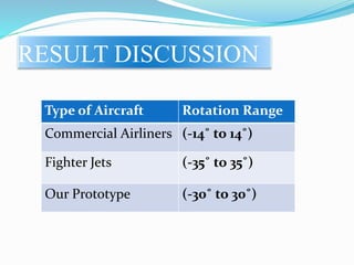
T.E. MINI PROJECT
Design and Fabrication of Fly-by-Wire
System for Flight Control
JUBIN GOEL (T8023065)
ANKIT KARMAKAR (T8023069)
YOGESH SONULE (T8023155)
Internal Guide – Prof. Alwin Anuse
Wire
By
Fly
FLIGHT
USING ELECTRONIC
CONTROL
HOW DOES IT WORK
 Input from various Pilot Controls:
 Steer Column
 Foot Pedals
 Throttle Control
is taken in the form of analog inputs, converted
to electronic signals which is sent via the Flight
Computer to the actuators controlling the Flight
Surfaces.
CURRENT TRENDS
Almost all Military and Civil Aircraft are now using
this technology.
State-of-the-Art military aircraft like the F-22 Raptor
of the USAF and milestone civilian aircraft like the
A380 from Airbus rely on highly advanced FBW
systems.
Power-By Wire
Fly-By Optics
SCOPE
Fly-By Wireless
FBW systems are under test for incorporation with
REMOTE FLIGHT ASSISTANCE SYSTEMS in case of
emergencies.
More sophisticated and ‘SMARTER’ Flight Computers
for increased performance and safety.
The 3 Critical Flight Parameters that we
need to control
YAW MOVEMENT
PITCH MOVEMENT
ROLL MOVEMENT
How do we do it?
We have attached 3 servo-motors with three wooden
‘wings’.
By sending precise ON-OFF Pulse trains to the servo,
we plan to move the Elevators and the Rudder of the
model, to and fro of the stable position.
The magnitude and direction of these movements will
be determined by the use of 6 Push-switches.
BLOCK DIAGRAM
UP
DOWN
RIGHT
LEFT
BANKING
LEFT
RIGHT
BANKING
A
T
M
E
G
A
8
M1 => Left Wing Flap M2=> Right Wing Flap M3 => Tail-plane
Motor Motor Motor
M1
M2
M3
SYSTEM ALGORITHM
START
INITIALIZE I/P & O/P OF µC
INITIALIZE ALL SERVOS TO THEIR INITIAL
POSITIONS
SCAN ALL JOYSTICK KEYS
GET KEYCODE OF RESP. KEY PRESSED
ROTATE SERVOS TO DESIRED POSITIONS
&
HOLD UNTILL KEY IS RELEASED
COMPONENT SELECTION CRITERIA
 µController: ATMEGA8
1. 3 PWM control required
2. Compactness of circuit
3. Resources available – availability of hardware and
software needed for programming and construction of
ckt.
4. 6 Analog Inputs
5. Cost-effective
Actuator: SERVO MOTOR – FUTABA S3003
1. Positioning Control by rotation around an axis
2. Precise control over rotary movement
3. Reasonable power consumption
4. Lightweight
5. Sufficient Torque
6. Market availability
in case of Damage or needed replacement.
COMPONENT SELECTION CRITERIA
SIMULATION IN PROTEUS
SIMULATION WAVEFORMS
SYSTEM SPECIFICATIONS
 Input Power Supply: DC 12V, 2A
µController: ATMEGA8
System Operating Frequency: 1MHz (Internal Clock)
Servo Ratings: 4.8V-6V, 500mA
Servo Motor Frequency: 414.66Hz
Joystick Input Voltage: 5V DC
Servo Motor Rotation Range: -30˚to +30˚ w.r.t. horizontal
level
RESULT DISCUSSION
Type of Aircraft Rotation Range
Commercial Airliners (-14˚ to 14˚)
Fighter Jets (-35˚ to 35˚)
Our Prototype (-30˚ to 30˚)
REFERENCES
Websites:
1. www.electronics-lab.com
2. www.et06.com/atmega_timers
3. www.avrfreaks.net
4. www.extremelectronics.co.in
Books:
The AVR Microcontrollers and Embedded Systems Using
Assembly And C
-By Muhammad Ali Mazidi
Sarmad Naimi
Sepher Naimi
THANK YOU…

Fly By Wire

  • 1.
    T.E. MINI PROJECT Designand Fabrication of Fly-by-Wire System for Flight Control JUBIN GOEL (T8023065) ANKIT KARMAKAR (T8023069) YOGESH SONULE (T8023155) Internal Guide – Prof. Alwin Anuse
  • 2.
  • 3.
    HOW DOES ITWORK  Input from various Pilot Controls:  Steer Column  Foot Pedals  Throttle Control is taken in the form of analog inputs, converted to electronic signals which is sent via the Flight Computer to the actuators controlling the Flight Surfaces.
  • 4.
    CURRENT TRENDS Almost allMilitary and Civil Aircraft are now using this technology. State-of-the-Art military aircraft like the F-22 Raptor of the USAF and milestone civilian aircraft like the A380 from Airbus rely on highly advanced FBW systems. Power-By Wire Fly-By Optics
  • 5.
    SCOPE Fly-By Wireless FBW systemsare under test for incorporation with REMOTE FLIGHT ASSISTANCE SYSTEMS in case of emergencies. More sophisticated and ‘SMARTER’ Flight Computers for increased performance and safety.
  • 6.
    The 3 CriticalFlight Parameters that we need to control YAW MOVEMENT PITCH MOVEMENT ROLL MOVEMENT
  • 7.
    How do wedo it? We have attached 3 servo-motors with three wooden ‘wings’. By sending precise ON-OFF Pulse trains to the servo, we plan to move the Elevators and the Rudder of the model, to and fro of the stable position. The magnitude and direction of these movements will be determined by the use of 6 Push-switches.
  • 8.
    BLOCK DIAGRAM UP DOWN RIGHT LEFT BANKING LEFT RIGHT BANKING A T M E G A 8 M1 =>Left Wing Flap M2=> Right Wing Flap M3 => Tail-plane Motor Motor Motor M1 M2 M3
  • 9.
    SYSTEM ALGORITHM START INITIALIZE I/P& O/P OF µC INITIALIZE ALL SERVOS TO THEIR INITIAL POSITIONS SCAN ALL JOYSTICK KEYS GET KEYCODE OF RESP. KEY PRESSED ROTATE SERVOS TO DESIRED POSITIONS & HOLD UNTILL KEY IS RELEASED
  • 10.
    COMPONENT SELECTION CRITERIA µController: ATMEGA8 1. 3 PWM control required 2. Compactness of circuit 3. Resources available – availability of hardware and software needed for programming and construction of ckt. 4. 6 Analog Inputs 5. Cost-effective
  • 11.
    Actuator: SERVO MOTOR– FUTABA S3003 1. Positioning Control by rotation around an axis 2. Precise control over rotary movement 3. Reasonable power consumption 4. Lightweight 5. Sufficient Torque 6. Market availability in case of Damage or needed replacement. COMPONENT SELECTION CRITERIA
  • 12.
  • 13.
  • 14.
    SYSTEM SPECIFICATIONS  InputPower Supply: DC 12V, 2A µController: ATMEGA8 System Operating Frequency: 1MHz (Internal Clock) Servo Ratings: 4.8V-6V, 500mA Servo Motor Frequency: 414.66Hz Joystick Input Voltage: 5V DC Servo Motor Rotation Range: -30˚to +30˚ w.r.t. horizontal level
  • 15.
    RESULT DISCUSSION Type ofAircraft Rotation Range Commercial Airliners (-14˚ to 14˚) Fighter Jets (-35˚ to 35˚) Our Prototype (-30˚ to 30˚)
  • 16.
    REFERENCES Websites: 1. www.electronics-lab.com 2. www.et06.com/atmega_timers 3.www.avrfreaks.net 4. www.extremelectronics.co.in Books: The AVR Microcontrollers and Embedded Systems Using Assembly And C -By Muhammad Ali Mazidi Sarmad Naimi Sepher Naimi
  • 17.

Editor's Notes

  • #3 Replaces the conventional manual flight controls of an aircraft with an electronic interface WHY FLY-BY-WIRE Flight control is now easier, and physically less strenuous and challenging. Mechanical and Hydraulic Systems are prone to damage in combat. FBW ensures reliability and good functionality despite damage to MILITARY AIRCRAFT. In case of malfunction, easier to repair/replace. Allows AI interference and computer assisted control for better and safer operation of aircraft.
  • #5 2.Power-By Wire: The new flight control subsystems package includes a power-on-demand electrical system and electric actuation (rather than the traditional, large, heavy and difficult-to-maintain hydraulic actuation) of flight control surfaces. The main adavantage of this system is that it can reduce the weight of the plane by almost 700 pounds.These systems are being utilized on military jest such as the F-16 fighter jet.A wireless system also has been developed. 3.Fly-By Optics: Fly-by-optics, also known as fly-by light, is a further development using fiber optic cables. Since fiber optic cables are the new and most advanced communication cables, they can prove to be highly convenient during operation of the control system. The fiber optic cables are highly durable and lightweight. Hence, these cables help in reducing the vehicle’s weight to a considerable extent.
  • #6 1.Fly-By Wireless: Wiring adds a considerable amount of weight to an aircraft; therefore, researchers are exploring implementing fly-by-wireless solutions. Fly-by-wireless systems are very similar to fly-by-wire systems, however, instead of using a wired protocol for the physical layer a wireless protocol is employed. In addition to reducing weight, implementing a wireless solution has the potential to reduce costs throughout an aircraft's life cycle. REMOTE FLIGHT ASSISTANCE SYSTEMS – control aircraft from outside the aircraft.