Download to read offline
![Ahmed Mohammed Int. Journal of Engineering Research and Applications www.ijera.com
ISSN : 2248-9622, Vol. 5, Issue 2, ( Part -2) February 2015, pp.126-129
www.ijera.com 129 | P a g e
… Decrease the stepper motors 1&2. elevator angle
gradually.
Return
Turn right subroutine:
… Display turn right on the LCD.
… Rotate stepper motors 3 clockwise.
Return
Turn left subroutine:
… Display turn left on the LCD.
… Rotate stepper motors 3 anticlockwise.
Return
Ascend subroutine:
… Display ascend on the LCD.
… Rotate stepper motors 1&2 clockwise.
Return
Descend subroutine:
… Display descend on the LCD.
… Rotate stepper motors 1 &2 anticlockwise.
Return
Landing subroutine:
… Display landing on the LCD.
… Activate stepper motors 1&2 for max. air drug
angle.
Return
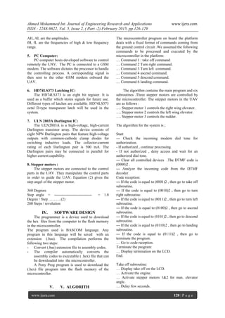
VI. RESULTS
Many commands have been send from the ground
control circuit to the UAV. Table (1) shows the
results while sending the commands from the control
circuit .
Table (1) Results of sending the commands from the
control circuit to the UAV
Ground circuit
command No.
DTMF
output in
Binary
Action performed
by the Drone
1 (0001)2 Take off
2 (0010)2 Turn right
3 (0011)2 Turn left
4 (0100)2 Ascend
5 (0101)2 Descend
6 (0110)2 Landing
The commands are executed and the platform
performed the relative action. During the experiment
some malfunctions occurred. The malfunctions are
expected to happen.
VII. CONCLSION
This paper adopts a concept to design a system that
acts to receive commands to control the platform in
all its operations. Display units are connected to the
platform to help in monitoring the system operation
in the development phase. The control system is
based on implementing the DTMF technology that
effectively allows control from remote area to the
desired location. The system design is dynamic and
further development and modification can be done .
The system is made simple and user friendly.
REFERANCES
[1.] Mazidi Muhammed Ali, The 8051
microcontroller and Embedded system,
Prentic Hall, 2007
[2.] © MSC Electronic, BASCOM – AVR, Help
Reference V1.11.8.3, 2006
[3.] Jan Axelson, Microcontroller idea book,
Copy right 1999.
[4.] Thomas L. Floyd,Electronic Devices 2nd
Ed.,Merill Publishing ompany,2003.
[5.] Daniel P. Raymer, Aircraft Design:
Conceptual Approach (Second Edition
2002).
[6.] Ihan Tuzcu Dynamics and control of flexible
Aircraft (Blacksburg, Virginia 2001).
[7.] http://diydrones.com.
[8.] http://www.nationaldefensemagazine.org](https://image.slidesharecdn.com/u50202126129-150321034019-conversion-gate01/85/U50202126129-4-320.jpg)

This document describes the design of an electronic remote control system for an unguided airborne vehicle (UAV) using dual tone multiple frequency (DTMF) technology. A microcontroller on the UAV analyzes DTMF commands received from a ground control station via GSM to control motors that manipulate the wings, elevators, and rudders. The microcontroller displays the UAV's operations on an LCD. Commands were successfully sent to control takeoff, turning, ascending, descending, and landing of the UAV. The simple, low-cost system allows remote control of the UAV from a distance via an existing GSM network.