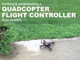
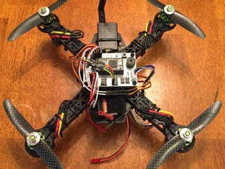
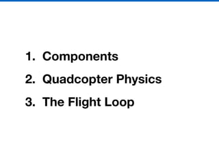
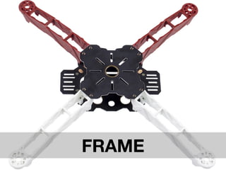
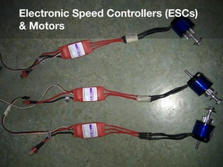
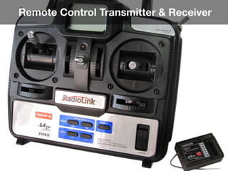
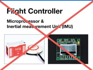
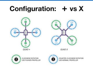
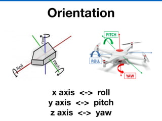
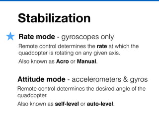
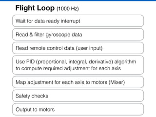
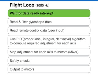
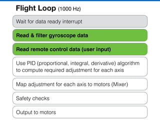
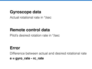
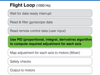
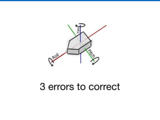
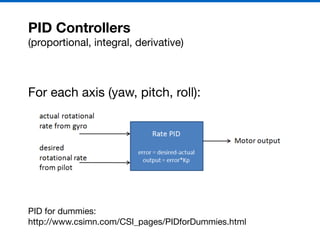
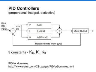
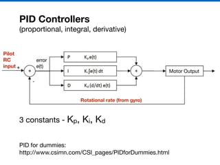
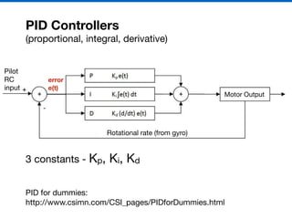
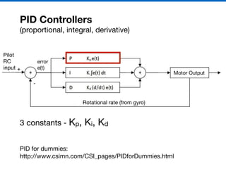
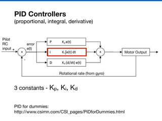
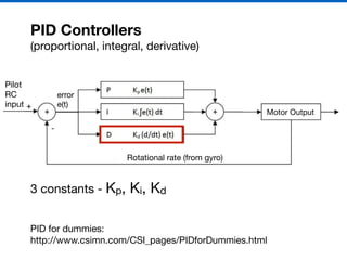
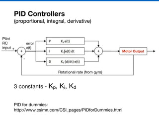
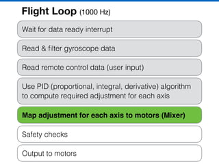
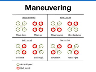
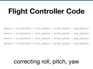
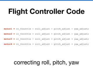
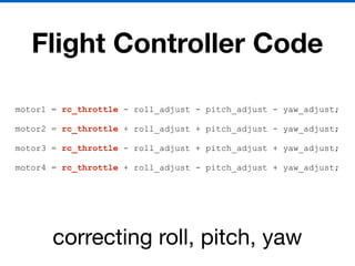
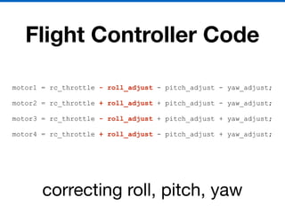
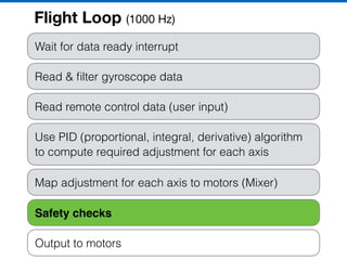
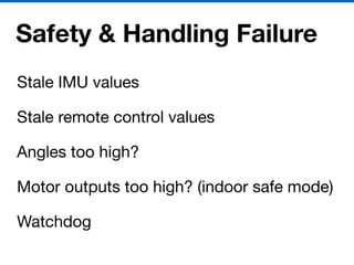
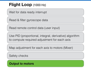
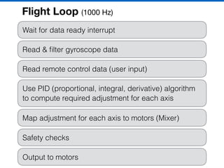
QUADCOPTER
FLIGHT CONTROLLER
building & programming a
from scratch
I’m Ryan Boland

Web Developer

@ Tanooki Labs
@bolandrm (github, twitter)
1. Components
2. Quadcopter Physics
3. The Flight Loop
FRAME
Electronic Speed Controllers (ESCs)
& Motors
Lithium Polymer (LiPo) Battery
Remote Control Transmitter & Receiver
Flight Controller
Microprocessor &
Inertial measurement Unit (IMU)
My Project - Custom Flight Controller
Arduino Mega 2560
& Prototyping Shield
8-bit AVR
16 MHz clock
256K Flash
8K Ram
Arduino Nano Clone
8-bit AVR
16 MHz clock
32K Flash
2K Ram
Teensy 3.1
32-bit ARM
96 MHz clock
256K Flash
64K Ram
$5$55 $20
Custom
PCB
Inertial Measurement Unit
MPU6050 - 3 axis gyroscope, 3 axis accelerometer
HMC5883L - 3 axis magnetometer
BMP180 - Barometer
GY-87
$8
Flight
Configuration: + vs X
Orientation
x axis <-> roll
y axis <-> pitch
z axis <-> yaw
Maneuvering
Stabilization
Rate mode - gyroscopes only
Remote control determines the rate at which the
quadcopter is rotating on any given axis.
Also known as Acro or Manual.
Attitude mode - accelerometers & gyros
Remote control determines the desired angle of the
quadcopter.
Also known as self-level or auto-level.
Wait for data ready interrupt
Read & filter gyroscope data
Read remote control data (user input)
Use PID (proportional, integral, derivative) algorithm
to compute required adjustment for each axis
Map adjustment for each axis to motors (Mixer)
Safety checks
Output to motors
Flight Loop (1000 Hz)
Wait for data ready interrupt
Read & filter gyroscope data
Read remote control data (user input)
Use PID (proportional, integral, derivative) algorithm
to compute required adjustment for each axis
Map adjustment for each axis to motors (Mixer)
Safety checks
Output to motors
Flight Loop (1000 Hz)
Wait for data ready interrupt
Read & filter gyroscope data
Read remote control data (user input)
Use PID (proportional, integral, derivative) algorithm
to compute required adjustment for each axis
Map adjustment for each axis to motors (Mixer)
Safety checks
Output to motors
Flight Loop (1000 Hz)
Gyroscope data
Actual rotational rate in °/sec
Remote control data
Pilot’s desired rotation rate in °/sec
Error
Difference between actual and desired rotational rate
e = gyro_rate - rc_rate
Wait for data ready interrupt
Read & filter gyroscope data
Read remote control data (user input)
Use PID (proportional, integral, derivative) algorithm
to compute required adjustment for each axis
Map adjustment for each axis to motors (Mixer)
Safety checks
Output to motors
Flight Loop (1000 Hz)
3 errors to correct
PID Controllers
(proportional, integral, derivative)
For each axis (yaw, pitch, roll):
PID for dummies:

http://www.csimn.com/CSI_pages/PIDforDummies.html
PID Controllers
(proportional, integral, derivative)
PID for dummies:

http://www.csimn.com/CSI_pages/PIDforDummies.html
Motor Output
Rotational rate (from gyro)
error

e(t)
Pilot

RC

input
3 constants - Kp, Ki, Kd
PID Controllers
(proportional, integral, derivative)
PID for dummies:

http://www.csimn.com/CSI_pages/PIDforDummies.html
Motor Output
Rotational rate (from gyro)
error

e(t)
Pilot
RC
input
3 constants - Kp, Ki, Kd
PID Controllers
(proportional, integral, derivative)
PID for dummies:

http://www.csimn.com/CSI_pages/PIDforDummies.html
Motor Output
Rotational rate (from gyro)
error
e(t)
Pilot

RC

input
3 constants - Kp, Ki, Kd
PID Controllers
(proportional, integral, derivative)
PID for dummies:

http://www.csimn.com/CSI_pages/PIDforDummies.html
Motor Output
Rotational rate (from gyro)
error

e(t)
Pilot

RC

input
3 constants - Kp, Ki, Kd
PID Controllers
(proportional, integral, derivative)
PID for dummies:

http://www.csimn.com/CSI_pages/PIDforDummies.html
Motor Output
Rotational rate (from gyro)
error

e(t)
Pilot

RC

input
3 constants - Kp, Ki, Kd
PID Controllers
(proportional, integral, derivative)
PID for dummies:

http://www.csimn.com/CSI_pages/PIDforDummies.html
Motor Output
Rotational rate (from gyro)
error

e(t)
Pilot

RC

input
3 constants - Kp, Ki, Kd
PID Controllers
(proportional, integral, derivative)
PID for dummies:

http://www.csimn.com/CSI_pages/PIDforDummies.html
Motor Output
Rotational rate (from gyro)
error

e(t)
Pilot

RC

input
3 constants - Kp, Ki, Kd
Wait for data ready interrupt
Read & filter gyroscope data
Read remote control data (user input)
Use PID (proportional, integral, derivative) algorithm
to compute required adjustment for each axis
Map adjustment for each axis to motors (Mixer)
Safety checks
Output to motors
Flight Loop (1000 Hz)
Maneuvering
Flight Controller Code
motor1 = rc_throttle - roll_adjust - pitch_adjust - yaw_adjust;
motor2 = rc_throttle + roll_adjust + pitch_adjust - yaw_adjust;
motor3 = rc_throttle - roll_adjust + pitch_adjust + yaw_adjust;
motor4 = rc_throttle + roll_adjust - pitch_adjust + yaw_adjust;
correcting roll, pitch, yaw
Wait for data ready interrupt
Read & filter gyroscope data
Read remote control data (user input)
Use PID (proportional, integral, derivative) algorithm
to compute required adjustment for each axis
Map adjustment for each axis to motors (Mixer)
Safety checks
Output to motors
Flight Loop (1000 Hz)
Safety & Handling Failure
Stale IMU values

Stale remote control values

Angles too high?

Motor outputs too high? (indoor safe mode)

Watchdog
Wait for data ready interrupt
Read & filter gyroscope data
Read remote control data (user input)
Use PID (proportional, integral, derivative) algorithm
to compute required adjustment for each axis
Map adjustment for each axis to motors (Mixer)
Safety checks
Output to motors
Flight Loop (1000 Hz)
Wait for data ready interrupt
Read & filter gyroscope data
Read remote control data (user input)
Use PID (proportional, integral, derivative) algorithm
to compute required adjustment for each axis
Map adjustment for each axis to motors (Mixer)
Safety checks
Output to motors
Flight Loop (1000 Hz)
Some Takeaways
Be Safe

Start small (mini quad
or balancing robot?)

Break things down
into subcomponents
Thanks!
@bolandrm

Quadcopter Talk (Abstractions)

  • 1.
    QUADCOPTER FLIGHT CONTROLLER building &programming a from scratch
  • 2.
    I’m Ryan Boland WebDeveloper @ Tanooki Labs @bolandrm (github, twitter)
  • 4.
    1. Components 2. QuadcopterPhysics 3. The Flight Loop
  • 5.
  • 6.
  • 7.
  • 8.
  • 9.
  • 10.
    My Project -Custom Flight Controller Arduino Mega 2560 & Prototyping Shield 8-bit AVR 16 MHz clock 256K Flash 8K Ram Arduino Nano Clone 8-bit AVR 16 MHz clock 32K Flash 2K Ram Teensy 3.1 32-bit ARM 96 MHz clock 256K Flash 64K Ram $5$55 $20
  • 11.
  • 12.
    Inertial Measurement Unit MPU6050- 3 axis gyroscope, 3 axis accelerometer HMC5883L - 3 axis magnetometer BMP180 - Barometer GY-87 $8
  • 13.
  • 14.
  • 15.
    Orientation x axis <->roll y axis <-> pitch z axis <-> yaw
  • 16.
  • 17.
    Stabilization Rate mode -gyroscopes only Remote control determines the rate at which the quadcopter is rotating on any given axis. Also known as Acro or Manual. Attitude mode - accelerometers & gyros Remote control determines the desired angle of the quadcopter. Also known as self-level or auto-level.
  • 18.
    Wait for dataready interrupt Read & filter gyroscope data Read remote control data (user input) Use PID (proportional, integral, derivative) algorithm to compute required adjustment for each axis Map adjustment for each axis to motors (Mixer) Safety checks Output to motors Flight Loop (1000 Hz)
  • 19.
    Wait for dataready interrupt Read & filter gyroscope data Read remote control data (user input) Use PID (proportional, integral, derivative) algorithm to compute required adjustment for each axis Map adjustment for each axis to motors (Mixer) Safety checks Output to motors Flight Loop (1000 Hz)
  • 20.
    Wait for dataready interrupt Read & filter gyroscope data Read remote control data (user input) Use PID (proportional, integral, derivative) algorithm to compute required adjustment for each axis Map adjustment for each axis to motors (Mixer) Safety checks Output to motors Flight Loop (1000 Hz)
  • 21.
    Gyroscope data Actual rotationalrate in °/sec Remote control data Pilot’s desired rotation rate in °/sec Error Difference between actual and desired rotational rate e = gyro_rate - rc_rate
  • 22.
    Wait for dataready interrupt Read & filter gyroscope data Read remote control data (user input) Use PID (proportional, integral, derivative) algorithm to compute required adjustment for each axis Map adjustment for each axis to motors (Mixer) Safety checks Output to motors Flight Loop (1000 Hz)
  • 23.
    3 errors tocorrect
  • 24.
    PID Controllers (proportional, integral,derivative) For each axis (yaw, pitch, roll): PID for dummies: http://www.csimn.com/CSI_pages/PIDforDummies.html
  • 25.
    PID Controllers (proportional, integral,derivative) PID for dummies: http://www.csimn.com/CSI_pages/PIDforDummies.html Motor Output Rotational rate (from gyro) error e(t) Pilot RC input 3 constants - Kp, Ki, Kd
  • 26.
    PID Controllers (proportional, integral,derivative) PID for dummies: http://www.csimn.com/CSI_pages/PIDforDummies.html Motor Output Rotational rate (from gyro) error e(t) Pilot RC input 3 constants - Kp, Ki, Kd
  • 27.
    PID Controllers (proportional, integral,derivative) PID for dummies: http://www.csimn.com/CSI_pages/PIDforDummies.html Motor Output Rotational rate (from gyro) error e(t) Pilot RC input 3 constants - Kp, Ki, Kd
  • 28.
    PID Controllers (proportional, integral,derivative) PID for dummies: http://www.csimn.com/CSI_pages/PIDforDummies.html Motor Output Rotational rate (from gyro) error e(t) Pilot RC input 3 constants - Kp, Ki, Kd
  • 29.
    PID Controllers (proportional, integral,derivative) PID for dummies: http://www.csimn.com/CSI_pages/PIDforDummies.html Motor Output Rotational rate (from gyro) error e(t) Pilot RC input 3 constants - Kp, Ki, Kd
  • 30.
    PID Controllers (proportional, integral,derivative) PID for dummies: http://www.csimn.com/CSI_pages/PIDforDummies.html Motor Output Rotational rate (from gyro) error e(t) Pilot RC input 3 constants - Kp, Ki, Kd
  • 31.
    PID Controllers (proportional, integral,derivative) PID for dummies: http://www.csimn.com/CSI_pages/PIDforDummies.html Motor Output Rotational rate (from gyro) error e(t) Pilot RC input 3 constants - Kp, Ki, Kd
  • 32.
    Wait for dataready interrupt Read & filter gyroscope data Read remote control data (user input) Use PID (proportional, integral, derivative) algorithm to compute required adjustment for each axis Map adjustment for each axis to motors (Mixer) Safety checks Output to motors Flight Loop (1000 Hz)
  • 33.
  • 34.
    Flight Controller Code motor1= rc_throttle - roll_adjust - pitch_adjust - yaw_adjust; motor2 = rc_throttle + roll_adjust + pitch_adjust - yaw_adjust; motor3 = rc_throttle - roll_adjust + pitch_adjust + yaw_adjust; motor4 = rc_throttle + roll_adjust - pitch_adjust + yaw_adjust; correcting roll, pitch, yaw
  • 35.
    Flight Controller Code motor1= rc_throttle - roll_adjust - pitch_adjust - yaw_adjust; motor2 = rc_throttle + roll_adjust + pitch_adjust - yaw_adjust; motor3 = rc_throttle - roll_adjust + pitch_adjust + yaw_adjust; motor4 = rc_throttle + roll_adjust - pitch_adjust + yaw_adjust; correcting roll, pitch, yaw
  • 36.
    Flight Controller Code motor1= rc_throttle - roll_adjust - pitch_adjust - yaw_adjust; motor2 = rc_throttle + roll_adjust + pitch_adjust - yaw_adjust; motor3 = rc_throttle - roll_adjust + pitch_adjust + yaw_adjust; motor4 = rc_throttle + roll_adjust - pitch_adjust + yaw_adjust; correcting roll, pitch, yaw
  • 37.
    Flight Controller Code motor1= rc_throttle - roll_adjust - pitch_adjust - yaw_adjust; motor2 = rc_throttle + roll_adjust + pitch_adjust - yaw_adjust; motor3 = rc_throttle - roll_adjust + pitch_adjust + yaw_adjust; motor4 = rc_throttle + roll_adjust - pitch_adjust + yaw_adjust; correcting roll, pitch, yaw
  • 38.
    Wait for dataready interrupt Read & filter gyroscope data Read remote control data (user input) Use PID (proportional, integral, derivative) algorithm to compute required adjustment for each axis Map adjustment for each axis to motors (Mixer) Safety checks Output to motors Flight Loop (1000 Hz)
  • 39.
    Safety & HandlingFailure Stale IMU values Stale remote control values Angles too high? Motor outputs too high? (indoor safe mode) Watchdog
  • 40.
    Wait for dataready interrupt Read & filter gyroscope data Read remote control data (user input) Use PID (proportional, integral, derivative) algorithm to compute required adjustment for each axis Map adjustment for each axis to motors (Mixer) Safety checks Output to motors Flight Loop (1000 Hz)
  • 41.
    Wait for dataready interrupt Read & filter gyroscope data Read remote control data (user input) Use PID (proportional, integral, derivative) algorithm to compute required adjustment for each axis Map adjustment for each axis to motors (Mixer) Safety checks Output to motors Flight Loop (1000 Hz)
  • 42.
    Some Takeaways Be Safe Startsmall (mini quad or balancing robot?) Break things down into subcomponents
  • 43.