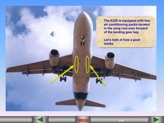
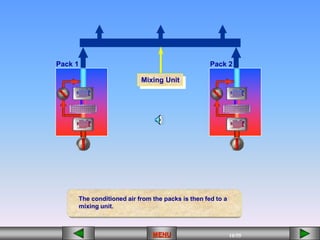
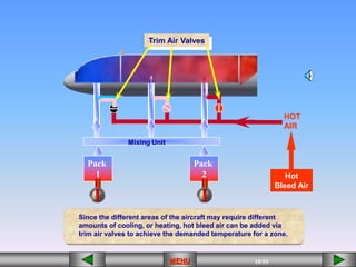
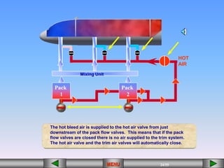
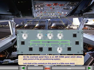
The document describes the air conditioning system on an Airbus A320, which uses two air conditioning packs to cool bleed air and distribute it to different zones of the aircraft. Hot air can be added to the zones via trim air valves to adjust the temperature. The cargo area also has a heating system that operates on similar principles to the main air conditioning system.

![14/55
MENU
[][][][][][] [][]
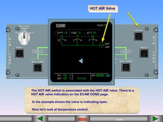
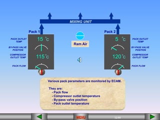
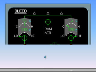
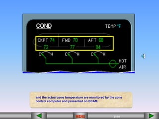
These parameters, along with the valve positions, are
displayed on the upper part of the ECAM BLEED page.](https://image.slidesharecdn.com/21-a-220601020625-2de9c863/85/21-A-PPT-14-320.jpg)


![29/55
MENU
[][][][][][] [][]
ECAM CRUISE Page
The ECAM CRUISE page also contains zone
temperature indications.](https://image.slidesharecdn.com/21-a-220601020625-2de9c863/85/21-A-PPT-29-320.jpg)

![32/55
MENU
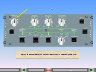
The PACK FLOW switches control their
associated pack flow control valves.
OFF
[][][][][][] [][]
OFF](https://image.slidesharecdn.com/21-a-220601020625-2de9c863/85/21-A-PPT-32-320.jpg)
![33/55
MENU
[][][][][][] [][]
OFF
In the example shown PACK 1 is selected off and is indicating
closed, while PACK 2 is selected on and is indicating open.
OFF](https://image.slidesharecdn.com/21-a-220601020625-2de9c863/85/21-A-PPT-33-320.jpg)
![35/55
MENU
[][][][][][] [][]
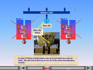
The guarded RAM AIR switch controls the RAM AIR valve.
In the example shown the RAM AIR valve is indicating closed.
Use of the RAM AIR switch is restricted to abnormal
conditions that will be discussed later.](https://image.slidesharecdn.com/21-a-220601020625-2de9c863/85/21-A-PPT-35-320.jpg)