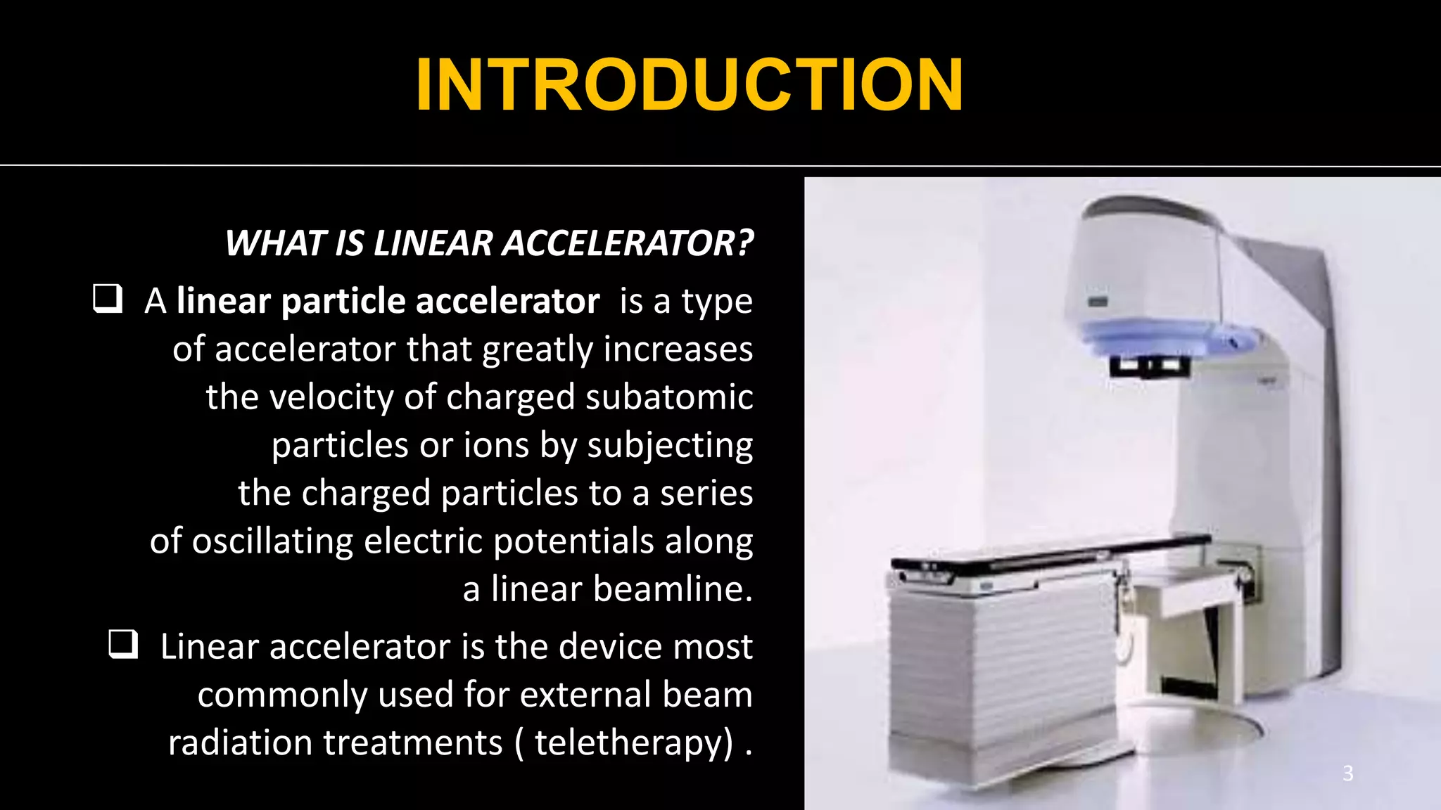
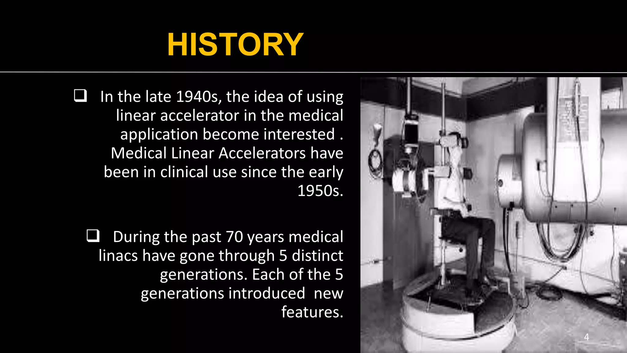
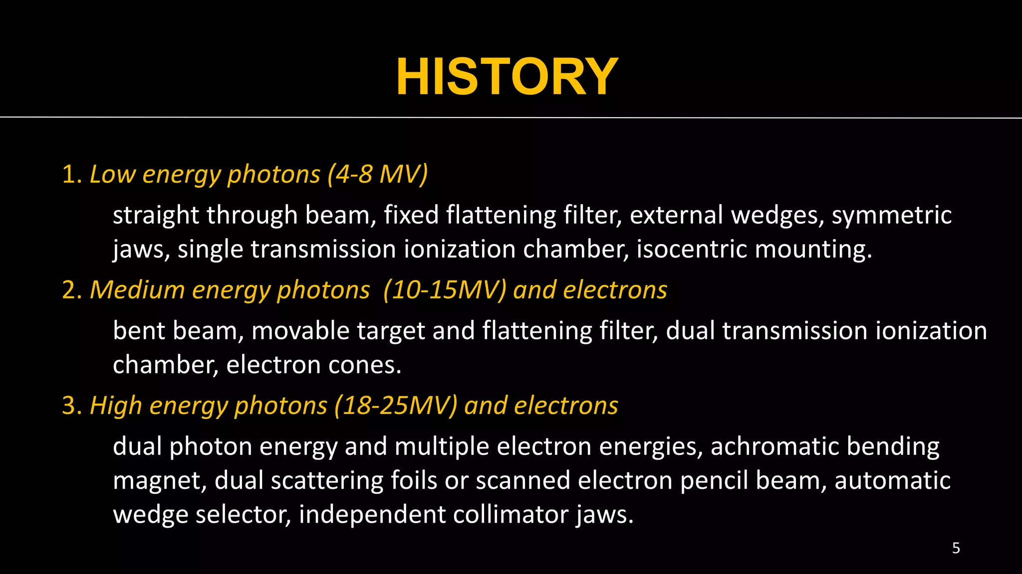
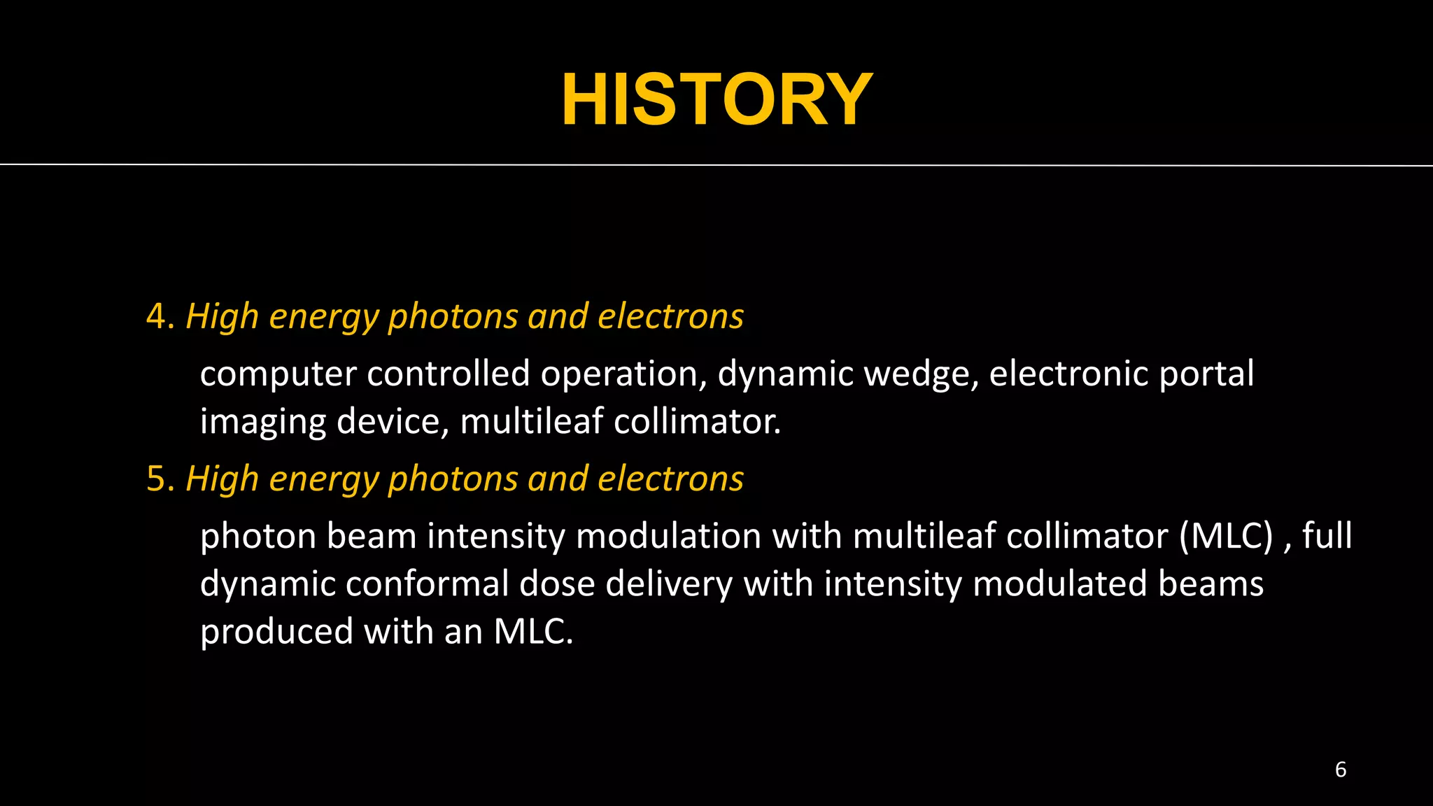
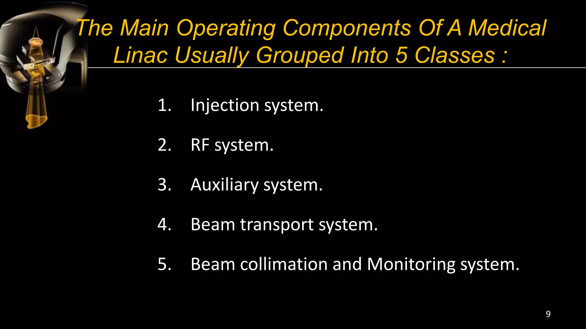
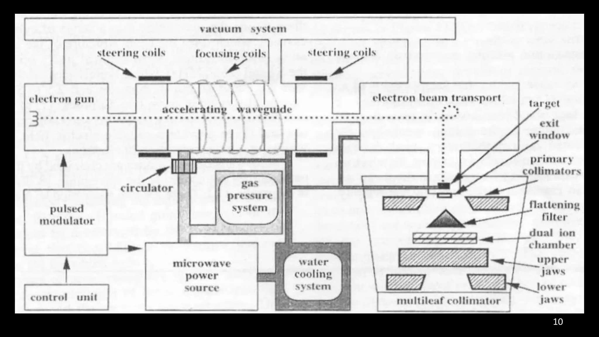
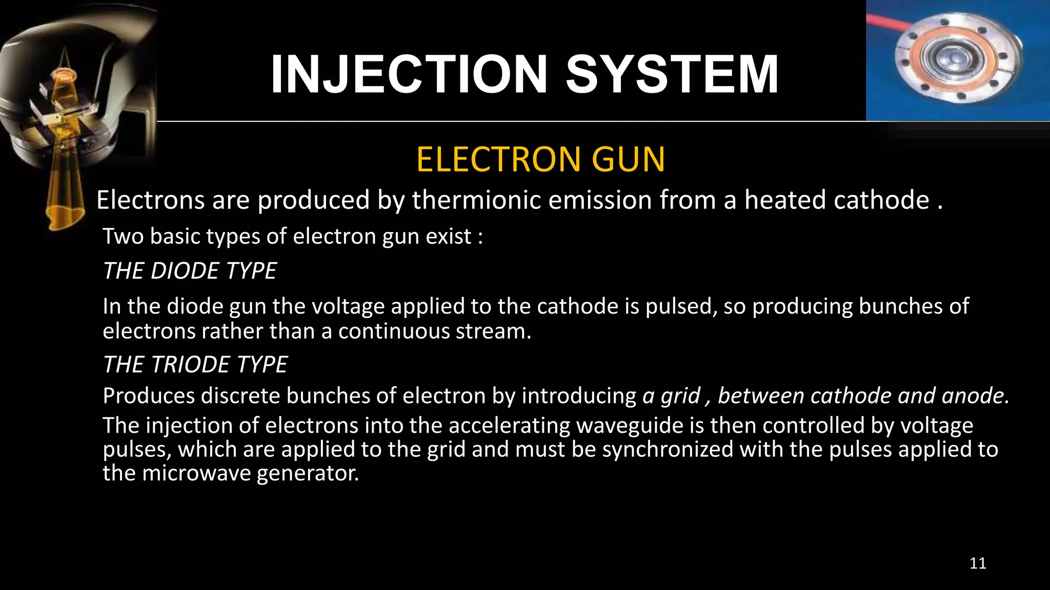
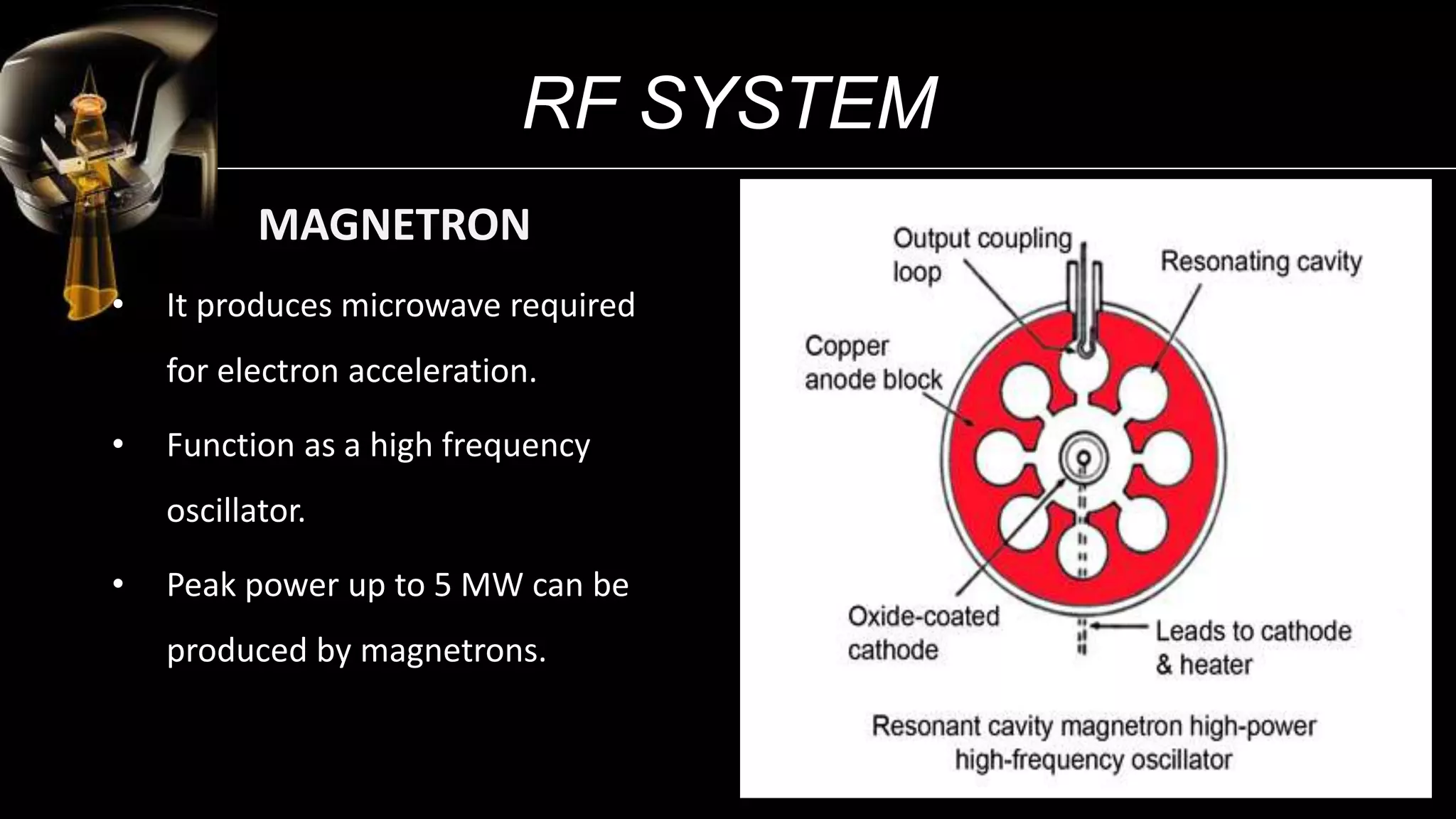
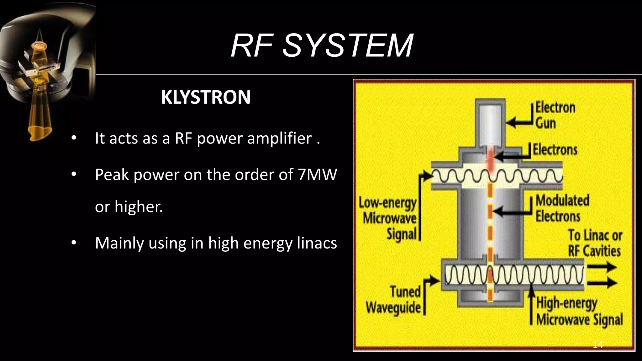
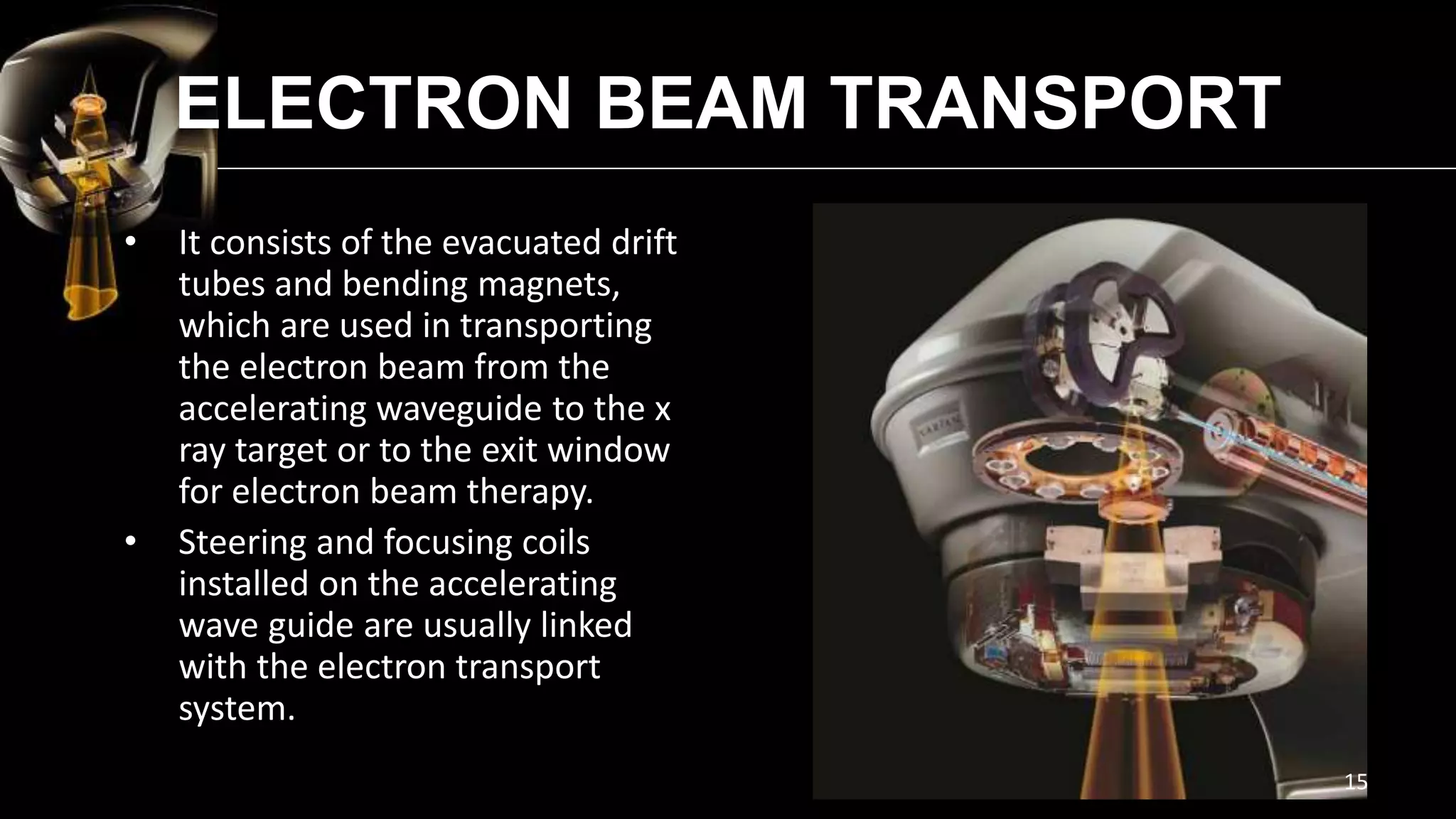
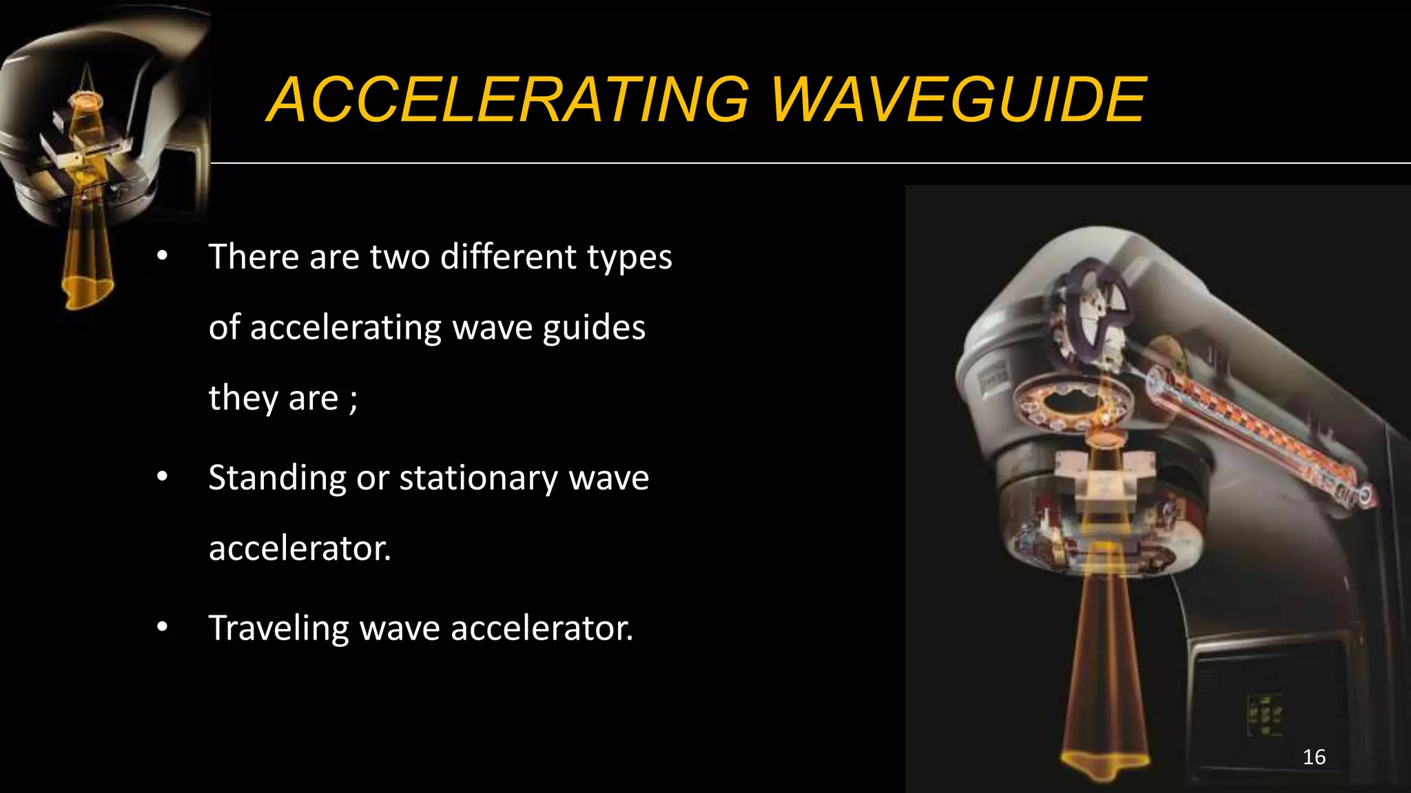
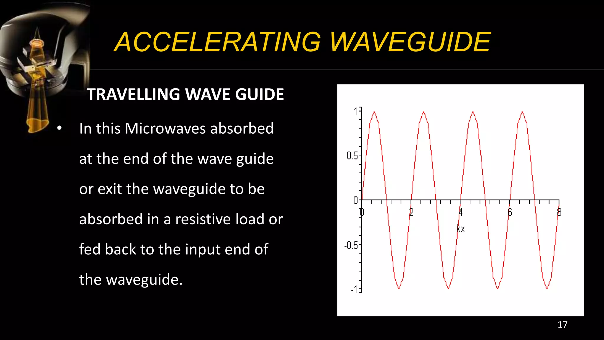
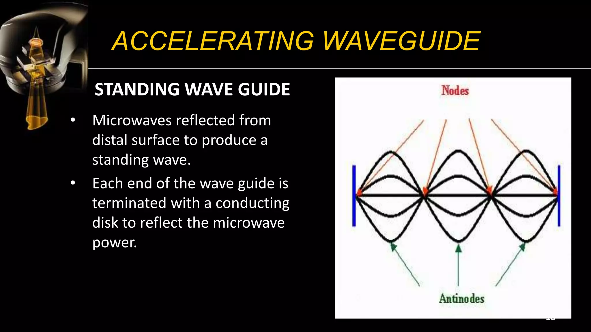
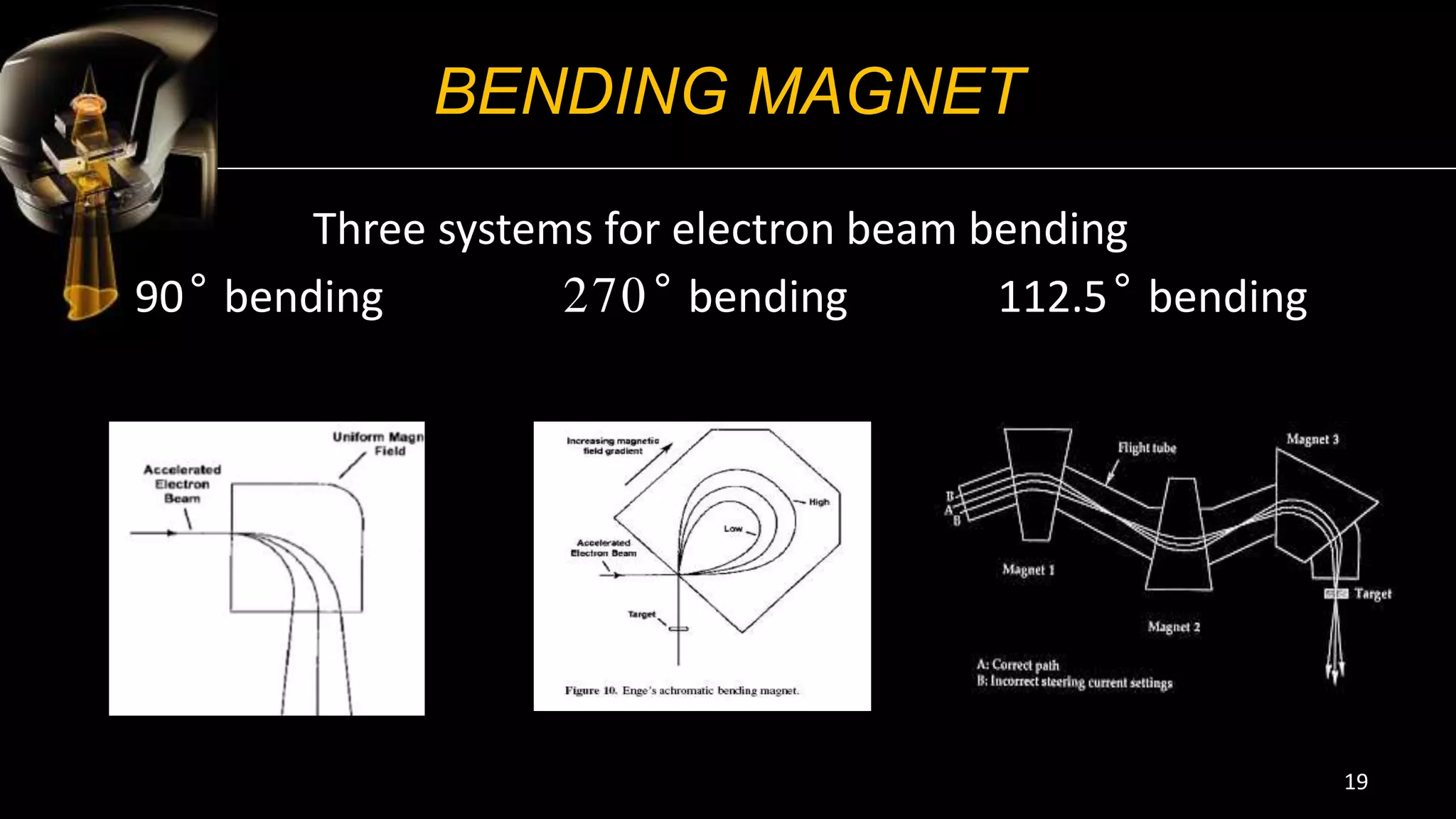
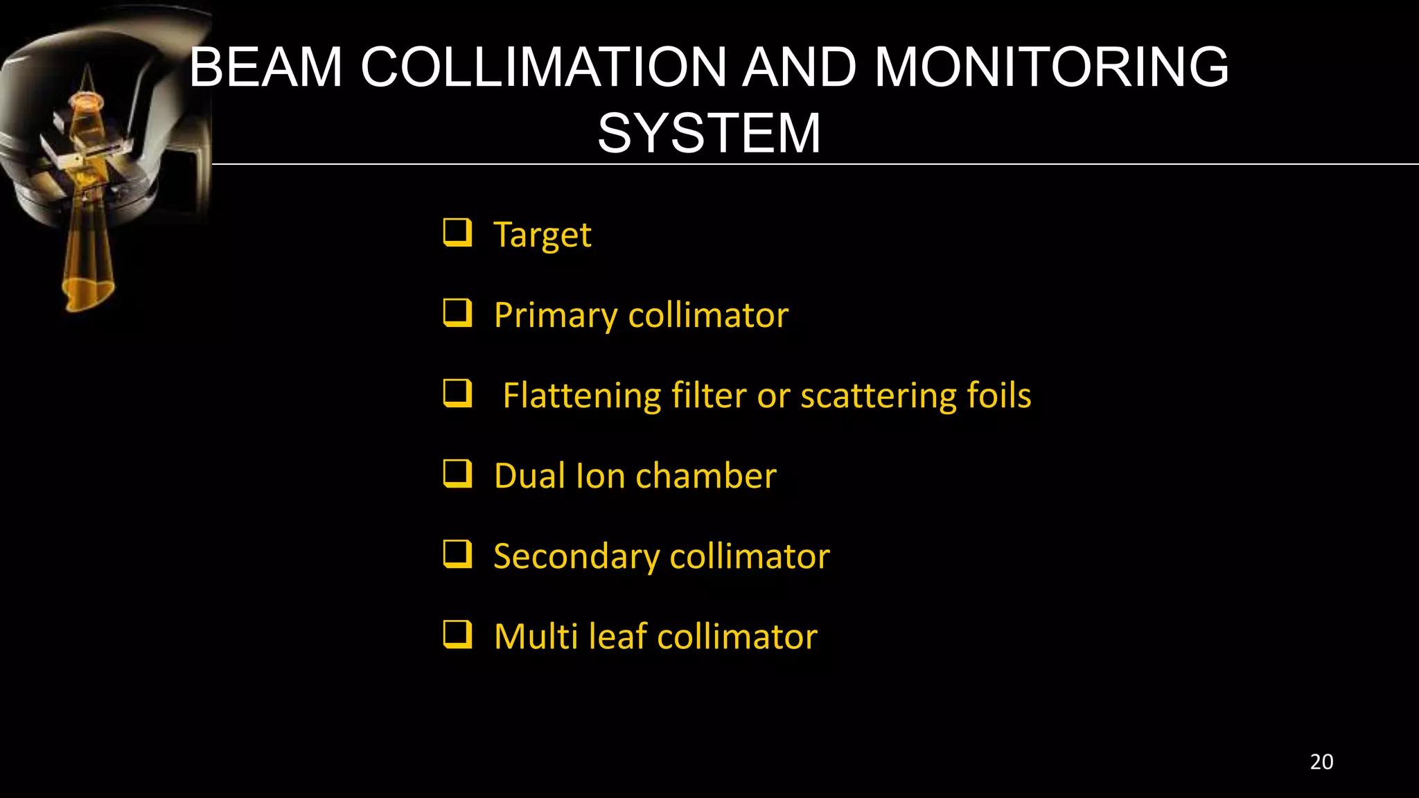
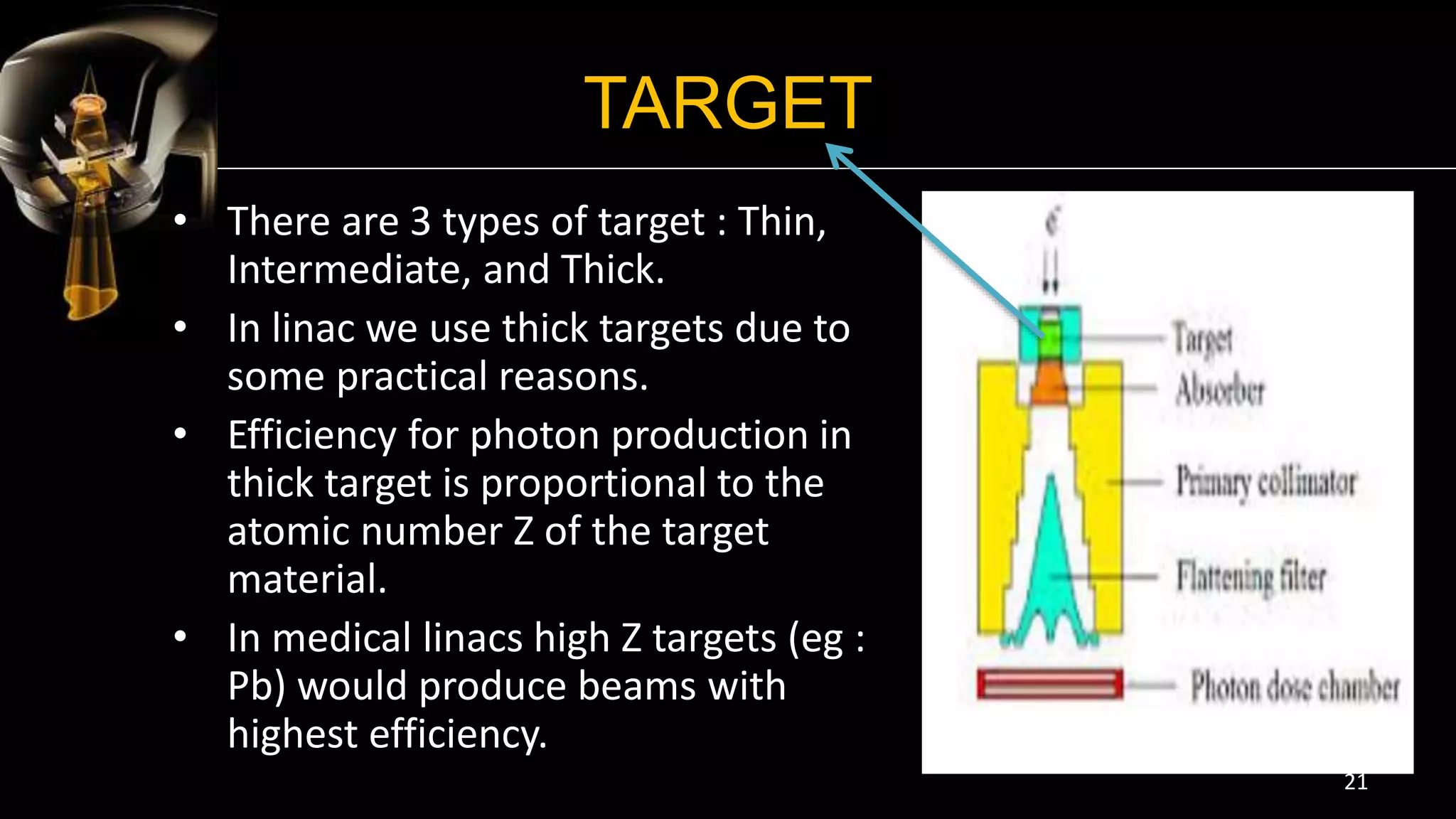
LINEAR ACCELERATOR
1
SAILAKSHMI . P
MSc. Radiation Physics
University of Calicut
I N S L I D E S
 Introduction
 History
 Components
1. Injection system.
2. RF system.
3. Auxiliary system.
4. Beam transport system.
5. Beam collimation and Monitoring system.
 Treatment couch
2
INTRODUCTION
WHAT IS LINEAR ACCELERATOR?
 A linear particle accelerator is a type
of accelerator that greatly increases
the velocity of charged subatomic
particles or ions by subjecting
the charged particles to a series
of oscillating electric potentials along
a linear beamline.
 Linear accelerator is the device most
commonly used for external beam
radiation treatments ( teletherapy) .
3
HISTORY
 In the late 1940s, the idea of using
linear accelerator in the medical
application become interested .
Medical Linear Accelerators have
been in clinical use since the early
1950s.
 During the past 70 years medical
linacs have gone through 5 distinct
generations. Each of the 5
generations introduced new
features.
4
HISTORY
1. Low energy photons (4-8 MV)
straight through beam, fixed flattening filter, external wedges, symmetric
jaws, single transmission ionization chamber, isocentric mounting.
2. Medium energy photons (10-15MV) and electrons
bent beam, movable target and flattening filter, dual transmission ionization
chamber, electron cones.
3. High energy photons (18-25MV) and electrons
dual photon energy and multiple electron energies, achromatic bending
magnet, dual scattering foils or scanned electron pencil beam, automatic
wedge selector, independent collimator jaws.
5
HISTORY
4. High energy photons and electrons
computer controlled operation, dynamic wedge, electronic portal
imaging device, multileaf collimator.
5. High energy photons and electrons
photon beam intensity modulation with multileaf collimator (MLC) , full
dynamic conformal dose delivery with intensity modulated beams
produced with an MLC.
6
HOW DOES IT WORK ?
• The linear accelerator uses microwave technology to accelerate electrons
in a part of the accelerator called the "wave guide", then allows these
electrons to collide with a heavy metal target. As a result of the collisions,
high-energy photons are produced from the target.
• The high energy x-rays will be directed to the patient’s tumor and shaped
as they exit the machine to conform to the shape of the patient’s tumor.
Radiation can be delivered to the tumor from any angle by rotating the
gantry and moving the treatment couch.
7
8
The Main Operating Components Of A Medical
Linac Usually Grouped Into 5 Classes :
1. Injection system.
2. RF system.
3. Auxiliary system.
4. Beam transport system.
5. Beam collimation and Monitoring system.
9
10
INJECTION SYSTEM
ELECTRON GUN
Electrons are produced by thermionic emission from a heated
cathode .
Two basic types of electron gun exist :
THE DIODE TYPE
In the diode gun the voltage applied to the cathode is pulsed, so producing
bunches of electrons rather than a continuous stream.
THE TRIODE TYPE
Produces discrete bunches of electron by introducing a grid , between cathode
and anode.
The injection of electrons into the accelerating waveguide is then controlled by
voltage pulses, which are applied to the grid and must be synchronized with the
pulses applied to the microwave generator.
11
RF SYSTEM
• The electrons are accelerated in the accelerating wave guide using
high power RF fields. Which are set up in the accelerating wave guide
by microwave radiation.
• This radiation is produced by microwave generators that are either
magnetrons or klystrons.
12
RF SYSTEM
• It produces microwave required
for electron acceleration.
• Function as a high frequency
oscillator.
• Peak power up to 5 MW can be
produced by magnetrons.
MAGNETRON
13
RF SYSTEM
KLYSTRON
• It acts as a RF power amplifier .
• Peak power on the order of 7MW
or higher.
• Mainly using in high energy linacs
14
ELECTRON BEAM TRANSPORT
• It consists of the evacuated drift
tubes and bending magnets,
which are used in transporting
the electron beam from the
accelerating waveguide to the x
ray target or to the exit window
for electron beam therapy.
• Steering and focusing coils
installed on the accelerating
wave guide are usually linked
with the electron transport
system.
15
ACCELERATING WAVEGUIDE
• There are two different types
of accelerating wave guides
they are ;
• Standing or stationary wave
accelerator.
• Traveling wave accelerator.
16
ACCELERATING WAVEGUIDE
TRAVELLING WAVE GUIDE
• In this Microwaves absorbed
at the end of the wave guide
or exit the waveguide to be
absorbed in a resistive load or
fed back to the input end of
the waveguide.
17
ACCELERATING WAVEGUIDE
STANDING WAVE GUIDE
• Microwaves reflected from
distal surface to produce a
standing wave.
• Each end of the wave guide is
terminated with a conducting
disk to reflect the microwave
power.
18
BENDING MAGNET
Three systems for electron beam bending
90° bending 270° bending 112.5° bending
19
BEAM COLLIMATION AND MONITORING
SYSTEM
 Target
 Primary collimator
 Flattening filter or scattering foils
 Dual Ion chamber
 Secondary collimator
 Multi leaf collimator
20
TARGET
• There are 3 types of target : Thin,
Intermediate, and Thick.
• In linac we use thick targets due to
some practical reasons.
• Efficiency for photon production in
thick target is proportional to the
atomic number Z of the target
material.
• In medical linacs high Z targets (eg :
Pb) would produce beams with
highest efficiency.
21
PRIMARY COLLIMATOR
• It defines the largest available
circular field size and is
essentially a conical opening
projecting into a tungsten
shielding block.
• One end of the conical opening
of the collimator projecting onto
edges of the target and the
other to the flattening filter.
22
FLATTENING FILTER
• The photon dose distribution
produced by a linac is strongly
forward peaked.
• To make the beam intensity
uniform across the field, a
flattening filter is inserted in
the beam.
• The filter is usually made of
Pb, although tungsten,
uranium, steel , aluminum or a
combination has also
suggested.
23
DUAL IONIZATION CHAMBER
• The flattened beam is incident on the dose
monitoring chambers.
• The monitoring system consist of several
ion chambers or a single chamber with
multiple plates.
• The chambers are usually transmission
type, i.e., flat parallel plate or cylindrical
thimble chamber is used in some linacs.
24
SCATTERING FOILS
• In the electron mode of linac
operation , the beam instead of
striking the target , is made to
strike an electron scattering foil
to spread the beam as well as get
a uniform electron fluence across
the treatment field.
• It consist of a thin metallic foil,
usually of lead.
25
SECONDARY COLLIMATOR
• It consist of four blocks, two forming
the upper and two forming the lower
jaws.
• Provide rectangular or square field at
the linac isocenter.
• Usually made of lead or tungsten.
26
MULTILEAF COLLIMATOR
• Using MLC’s we can conform the
treatment fields to the tumor
volume.
• The number of leaves in the
commercial MLC’s are steadily
increasing.
• leaves: 82, 120,160 & width: 1cm
and 1.5 to 6mm is currently
available.
• Each leaves is controlled by
computer controlled motors.
27
28
TREATMENT COUCH
 The treatment couch is the area on which
patient’s are positioned to receive their
radiation treatment, and it has the ability
to move
• up/ down
• Right /left
• In/out
• Hexapod (currently 6 degrees of motions
are available)
 The linac couch 6D displacements
are vertical, longitudinal, lateral, yaw, roll
and pitch
29
30

Linear Accelerator

  • 1.
    LINEAR ACCELERATOR 1 SAILAKSHMI .P MSc. Radiation Physics University of Calicut
  • 2.
    I N SL I D E S  Introduction  History  Components 1. Injection system. 2. RF system. 3. Auxiliary system. 4. Beam transport system. 5. Beam collimation and Monitoring system.  Treatment couch 2
  • 3.
    INTRODUCTION WHAT IS LINEARACCELERATOR?  A linear particle accelerator is a type of accelerator that greatly increases the velocity of charged subatomic particles or ions by subjecting the charged particles to a series of oscillating electric potentials along a linear beamline.  Linear accelerator is the device most commonly used for external beam radiation treatments ( teletherapy) . 3
  • 4.
    HISTORY  In thelate 1940s, the idea of using linear accelerator in the medical application become interested . Medical Linear Accelerators have been in clinical use since the early 1950s.  During the past 70 years medical linacs have gone through 5 distinct generations. Each of the 5 generations introduced new features. 4
  • 5.
    HISTORY 1. Low energyphotons (4-8 MV) straight through beam, fixed flattening filter, external wedges, symmetric jaws, single transmission ionization chamber, isocentric mounting. 2. Medium energy photons (10-15MV) and electrons bent beam, movable target and flattening filter, dual transmission ionization chamber, electron cones. 3. High energy photons (18-25MV) and electrons dual photon energy and multiple electron energies, achromatic bending magnet, dual scattering foils or scanned electron pencil beam, automatic wedge selector, independent collimator jaws. 5
  • 6.
    HISTORY 4. High energyphotons and electrons computer controlled operation, dynamic wedge, electronic portal imaging device, multileaf collimator. 5. High energy photons and electrons photon beam intensity modulation with multileaf collimator (MLC) , full dynamic conformal dose delivery with intensity modulated beams produced with an MLC. 6
  • 7.
    HOW DOES ITWORK ? • The linear accelerator uses microwave technology to accelerate electrons in a part of the accelerator called the "wave guide", then allows these electrons to collide with a heavy metal target. As a result of the collisions, high-energy photons are produced from the target. • The high energy x-rays will be directed to the patient’s tumor and shaped as they exit the machine to conform to the shape of the patient’s tumor. Radiation can be delivered to the tumor from any angle by rotating the gantry and moving the treatment couch. 7
  • 8.
  • 9.
    The Main OperatingComponents Of A Medical Linac Usually Grouped Into 5 Classes : 1. Injection system. 2. RF system. 3. Auxiliary system. 4. Beam transport system. 5. Beam collimation and Monitoring system. 9
  • 10.
  • 11.
    INJECTION SYSTEM ELECTRON GUN Electronsare produced by thermionic emission from a heated cathode . Two basic types of electron gun exist : THE DIODE TYPE In the diode gun the voltage applied to the cathode is pulsed, so producing bunches of electrons rather than a continuous stream. THE TRIODE TYPE Produces discrete bunches of electron by introducing a grid , between cathode and anode. The injection of electrons into the accelerating waveguide is then controlled by voltage pulses, which are applied to the grid and must be synchronized with the pulses applied to the microwave generator. 11
  • 12.
    RF SYSTEM • Theelectrons are accelerated in the accelerating wave guide using high power RF fields. Which are set up in the accelerating wave guide by microwave radiation. • This radiation is produced by microwave generators that are either magnetrons or klystrons. 12
  • 13.
    RF SYSTEM • Itproduces microwave required for electron acceleration. • Function as a high frequency oscillator. • Peak power up to 5 MW can be produced by magnetrons. MAGNETRON 13
  • 14.
    RF SYSTEM KLYSTRON • Itacts as a RF power amplifier . • Peak power on the order of 7MW or higher. • Mainly using in high energy linacs 14
  • 15.
    ELECTRON BEAM TRANSPORT •It consists of the evacuated drift tubes and bending magnets, which are used in transporting the electron beam from the accelerating waveguide to the x ray target or to the exit window for electron beam therapy. • Steering and focusing coils installed on the accelerating wave guide are usually linked with the electron transport system. 15
  • 16.
    ACCELERATING WAVEGUIDE • Thereare two different types of accelerating wave guides they are ; • Standing or stationary wave accelerator. • Traveling wave accelerator. 16
  • 17.
    ACCELERATING WAVEGUIDE TRAVELLING WAVEGUIDE • In this Microwaves absorbed at the end of the wave guide or exit the waveguide to be absorbed in a resistive load or fed back to the input end of the waveguide. 17
  • 18.
    ACCELERATING WAVEGUIDE STANDING WAVEGUIDE • Microwaves reflected from distal surface to produce a standing wave. • Each end of the wave guide is terminated with a conducting disk to reflect the microwave power. 18
  • 19.
    BENDING MAGNET Three systemsfor electron beam bending 90° bending 270° bending 112.5° bending 19
  • 20.
    BEAM COLLIMATION ANDMONITORING SYSTEM  Target  Primary collimator  Flattening filter or scattering foils  Dual Ion chamber  Secondary collimator  Multi leaf collimator 20
  • 21.
    TARGET • There are3 types of target : Thin, Intermediate, and Thick. • In linac we use thick targets due to some practical reasons. • Efficiency for photon production in thick target is proportional to the atomic number Z of the target material. • In medical linacs high Z targets (eg : Pb) would produce beams with highest efficiency. 21
  • 22.
    PRIMARY COLLIMATOR • Itdefines the largest available circular field size and is essentially a conical opening projecting into a tungsten shielding block. • One end of the conical opening of the collimator projecting onto edges of the target and the other to the flattening filter. 22
  • 23.
    FLATTENING FILTER • Thephoton dose distribution produced by a linac is strongly forward peaked. • To make the beam intensity uniform across the field, a flattening filter is inserted in the beam. • The filter is usually made of Pb, although tungsten, uranium, steel , aluminum or a combination has also suggested. 23
  • 24.
    DUAL IONIZATION CHAMBER •The flattened beam is incident on the dose monitoring chambers. • The monitoring system consist of several ion chambers or a single chamber with multiple plates. • The chambers are usually transmission type, i.e., flat parallel plate or cylindrical thimble chamber is used in some linacs. 24
  • 25.
    SCATTERING FOILS • Inthe electron mode of linac operation , the beam instead of striking the target , is made to strike an electron scattering foil to spread the beam as well as get a uniform electron fluence across the treatment field. • It consist of a thin metallic foil, usually of lead. 25
  • 26.
    SECONDARY COLLIMATOR • Itconsist of four blocks, two forming the upper and two forming the lower jaws. • Provide rectangular or square field at the linac isocenter. • Usually made of lead or tungsten. 26
  • 27.
    MULTILEAF COLLIMATOR • UsingMLC’s we can conform the treatment fields to the tumor volume. • The number of leaves in the commercial MLC’s are steadily increasing. • leaves: 82, 120,160 & width: 1cm and 1.5 to 6mm is currently available. • Each leaves is controlled by computer controlled motors. 27
  • 28.
  • 29.
    TREATMENT COUCH  Thetreatment couch is the area on which patient’s are positioned to receive their radiation treatment, and it has the ability to move • up/ down • Right /left • In/out • Hexapod (currently 6 degrees of motions are available)  The linac couch 6D displacements are vertical, longitudinal, lateral, yaw, roll and pitch 29
  • 30.