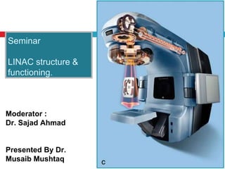
The seminar provided an overview of the LINAC structure and functioning. It began with an introduction by Dr. Sajad Ahmad and was presented by Dr. Musaib Mushtaq. The presentation covered the basic components and functioning of a LINAC including the electron gun, accelerator structure, and treatment head. It discussed the magnetron/klystron and how they generate microwave power used to accelerate electrons. It also explained the traveling wave and standing wave accelerator structures. The presentation provided details on auxiliary systems needed to operate the LINAC as well as advantages over cobalt-60 machines.
TISSUE PHANTOM RATIO - THE PHOTON BEAM QUALITY INDEXVictor Ekpo
TPR(20,10) is the recommended photon beam quality index by IAEA TRS-398 for megavoltage clinical photons generated by linear accelerators. This presentation goes through the basics of Tissue Phantom Ratio (TPR).
Radioisotopes and dose rates used for brachytherapySubhash Thakur
Radioisotopes and dose rates used for brachytherapy
This is the seminar about different radioisotopes used in brachytherapy beginning from radium to iradium and different dose rates, low dose rate, high dose rate used in brachytherapy. The significance of different dose rates and its radiobiology along with the clinical results.
brief but informative knowledge about what basically LINAC is and what is the phenomenon behind this machine ... easy to understand as well as presenting during lectures and in classes . share it
1.Stereotactic Radiosurgery (SRS)
SRS is a precise and focused delivery of a single, high dose of irradiation to a small and critically located intracranial volume while sparing normal structure
2.Stereotactic Body Radiation Therapy (SBRT)
SBRT is a treatment procedure similar to SRS, except that it deals extra-cranial radiosurgery
3.Flattening Filter Free (FFF) mode
FFF beam is produced without the use of flattening Filter
In the 1990s, several groups studied about FFF high-energy photon beams. The main interest for that, is to increase the dose rate for radiosurgery or the "physics interest”.
Need of increase in dose rate from traditional 300-600 to 1400-2400MU/min to overcome time-inefficiency and to improve patients comfort specially in SRS/SBRT
Flattening Filter Free (FFF) mode
FFF beam is produced without the use of flattening Filter
In the 1990s, several groups studied about FFF high-energy photon beams. The main interest for that, is to increase the dose rate for radiosurgery or the "physics interest”.
Need of increase in dose rate from traditional 300-600 to 1400-2400MU/min to overcome time-inefficiency and to improve patients comfort specially in SRS/SBRT
this power-point slide presentation includes lots of information like how MRI coil works. what is shimming, magnet, fringe, and design of mri coil and also magnet. this will help a lot for radiologist and technician radiographers.. thanks.
Flu Vaccine Alert in Bangalore Karnatakaaddon Scans
As flu season approaches, health officials in Bangalore, Karnataka, are urging residents to get their flu vaccinations. The seasonal flu, while common, can lead to severe health complications, particularly for vulnerable populations such as young children, the elderly, and those with underlying health conditions.
Dr. Vidisha Kumari, a leading epidemiologist in Bangalore, emphasizes the importance of getting vaccinated. "The flu vaccine is our best defense against the influenza virus. It not only protects individuals but also helps prevent the spread of the virus in our communities," he says.
This year, the flu season is expected to coincide with a potential increase in other respiratory illnesses. The Karnataka Health Department has launched an awareness campaign highlighting the significance of flu vaccinations. They have set up multiple vaccination centers across Bangalore, making it convenient for residents to receive their shots.
To encourage widespread vaccination, the government is also collaborating with local schools, workplaces, and community centers to facilitate vaccination drives. Special attention is being given to ensuring that the vaccine is accessible to all, including marginalized communities who may have limited access to healthcare.
Residents are reminded that the flu vaccine is safe and effective. Common side effects are mild and may include soreness at the injection site, mild fever, or muscle aches. These side effects are generally short-lived and far less severe than the flu itself.
Healthcare providers are also stressing the importance of continuing COVID-19 precautions. Wearing masks, practicing good hand hygiene, and maintaining social distancing are still crucial, especially in crowded places.
Protect yourself and your loved ones by getting vaccinated. Together, we can help keep Bangalore healthy and safe this flu season. For more information on vaccination centers and schedules, residents can visit the Karnataka Health Department’s official website or follow their social media pages.
Stay informed, stay safe, and get your flu shot today!
Explore natural remedies for syphilis treatment in Singapore. Discover alternative therapies, herbal remedies, and lifestyle changes that may complement conventional treatments. Learn about holistic approaches to managing syphilis symptoms and supporting overall health.
Recomendações da OMS sobre cuidados maternos e neonatais para uma experiência pós-natal positiva.
Em consonância com os ODS – Objetivos do Desenvolvimento Sustentável e a Estratégia Global para a Saúde das Mulheres, Crianças e Adolescentes, e aplicando uma abordagem baseada nos direitos humanos, os esforços de cuidados pós-natais devem expandir-se para além da cobertura e da simples sobrevivência, de modo a incluir cuidados de qualidade.
Estas diretrizes visam melhorar a qualidade dos cuidados pós-natais essenciais e de rotina prestados às mulheres e aos recém-nascidos, com o objetivo final de melhorar a saúde e o bem-estar materno e neonatal.
Uma “experiência pós-natal positiva” é um resultado importante para todas as mulheres que dão à luz e para os seus recém-nascidos, estabelecendo as bases para a melhoria da saúde e do bem-estar a curto e longo prazo. Uma experiência pós-natal positiva é definida como aquela em que as mulheres, pessoas que gestam, os recém-nascidos, os casais, os pais, os cuidadores e as famílias recebem informação consistente, garantia e apoio de profissionais de saúde motivados; e onde um sistema de saúde flexível e com recursos reconheça as necessidades das mulheres e dos bebês e respeite o seu contexto cultural.
Estas diretrizes consolidadas apresentam algumas recomendações novas e já bem fundamentadas sobre cuidados pós-natais de rotina para mulheres e neonatos que recebem cuidados no pós-parto em unidades de saúde ou na comunidade, independentemente dos recursos disponíveis.
É fornecido um conjunto abrangente de recomendações para cuidados durante o período puerperal, com ênfase nos cuidados essenciais que todas as mulheres e recém-nascidos devem receber, e com a devida atenção à qualidade dos cuidados; isto é, a entrega e a experiência do cuidado recebido. Estas diretrizes atualizam e ampliam as recomendações da OMS de 2014 sobre cuidados pós-natais da mãe e do recém-nascido e complementam as atuais diretrizes da OMS sobre a gestão de complicações pós-natais.
O estabelecimento da amamentação e o manejo das principais intercorrências é contemplada.
Recomendamos muito.
Vamos discutir essas recomendações no nosso curso de pós-graduação em Aleitamento no Instituto Ciclos.
Esta publicação só está disponível em inglês até o momento.
Prof. Marcus Renato de Carvalho
www.agostodourado.com
micro teaching on communication m.sc nursing.pdfAnurag Sharma
Microteaching is a unique model of practice teaching. It is a viable instrument for the. desired change in the teaching behavior or the behavior potential which, in specified types of real. classroom situations, tends to facilitate the achievement of specified types of objectives.
These lecture slides, by Dr Sidra Arshad, offer a quick overview of physiological basis of a normal electrocardiogram.
Learning objectives:
1. Define an electrocardiogram (ECG) and electrocardiography
2. Describe how dipoles generated by the heart produce the waveforms of the ECG
3. Describe the components of a normal electrocardiogram of a typical bipolar leads (limb II)
4. Differentiate between intervals and segments
5. Enlist some common indications for obtaining an ECG
Study Resources:
1. Chapter 11, Guyton and Hall Textbook of Medical Physiology, 14th edition
2. Chapter 9, Human Physiology - From Cells to Systems, Lauralee Sherwood, 9th edition
3. Chapter 29, Ganong’s Review of Medical Physiology, 26th edition
4. Electrocardiogram, StatPearls - https://www.ncbi.nlm.nih.gov/books/NBK549803/
5. ECG in Medical Practice by ABM Abdullah, 4th edition
6. ECG Basics, http://www.nataliescasebook.com/tag/e-c-g-basics
New Drug Discovery and Development .....NEHA GUPTA
The "New Drug Discovery and Development" process involves the identification, design, testing, and manufacturing of novel pharmaceutical compounds with the aim of introducing new and improved treatments for various medical conditions. This comprehensive endeavor encompasses various stages, including target identification, preclinical studies, clinical trials, regulatory approval, and post-market surveillance. It involves multidisciplinary collaboration among scientists, researchers, clinicians, regulatory experts, and pharmaceutical companies to bring innovative therapies to market and address unmet medical needs.
Ethanol (CH3CH2OH), or beverage alcohol, is a two-carbon alcohol
that is rapidly distributed in the body and brain. Ethanol alters many
neurochemical systems and has rewarding and addictive properties. It
is the oldest recreational drug and likely contributes to more morbidity,
mortality, and public health costs than all illicit drugs combined. The
5th edition of the Diagnostic and Statistical Manual of Mental Disorders
(DSM-5) integrates alcohol abuse and alcohol dependence into a single
disorder called alcohol use disorder (AUD), with mild, moderate,
and severe subclassifications (American Psychiatric Association, 2013).
In the DSM-5, all types of substance abuse and dependence have been
combined into a single substance use disorder (SUD) on a continuum
from mild to severe. A diagnosis of AUD requires that at least two of
the 11 DSM-5 behaviors be present within a 12-month period (mild
AUD: 2–3 criteria; moderate AUD: 4–5 criteria; severe AUD: 6–11 criteria).
The four main behavioral effects of AUD are impaired control over
drinking, negative social consequences, risky use, and altered physiological
effects (tolerance, withdrawal). This chapter presents an overview
of the prevalence and harmful consequences of AUD in the U.S.,
the systemic nature of the disease, neurocircuitry and stages of AUD,
comorbidities, fetal alcohol spectrum disorders, genetic risk factors, and
pharmacotherapies for AUD.
Title: Sense of Smell
Presenter: Dr. Faiza, Assistant Professor of Physiology
Qualifications:
MBBS (Best Graduate, AIMC Lahore)
FCPS Physiology
ICMT, CHPE, DHPE (STMU)
MPH (GC University, Faisalabad)
MBA (Virtual University of Pakistan)
Learning Objectives:
Describe the primary categories of smells and the concept of odor blindness.
Explain the structure and location of the olfactory membrane and mucosa, including the types and roles of cells involved in olfaction.
Describe the pathway and mechanisms of olfactory signal transmission from the olfactory receptors to the brain.
Illustrate the biochemical cascade triggered by odorant binding to olfactory receptors, including the role of G-proteins and second messengers in generating an action potential.
Identify different types of olfactory disorders such as anosmia, hyposmia, hyperosmia, and dysosmia, including their potential causes.
Key Topics:
Olfactory Genes:
3% of the human genome accounts for olfactory genes.
400 genes for odorant receptors.
Olfactory Membrane:
Located in the superior part of the nasal cavity.
Medially: Folds downward along the superior septum.
Laterally: Folds over the superior turbinate and upper surface of the middle turbinate.
Total surface area: 5-10 square centimeters.
Olfactory Mucosa:
Olfactory Cells: Bipolar nerve cells derived from the CNS (100 million), with 4-25 olfactory cilia per cell.
Sustentacular Cells: Produce mucus and maintain ionic and molecular environment.
Basal Cells: Replace worn-out olfactory cells with an average lifespan of 1-2 months.
Bowman’s Gland: Secretes mucus.
Stimulation of Olfactory Cells:
Odorant dissolves in mucus and attaches to receptors on olfactory cilia.
Involves a cascade effect through G-proteins and second messengers, leading to depolarization and action potential generation in the olfactory nerve.
Quality of a Good Odorant:
Small (3-20 Carbon atoms), volatile, water-soluble, and lipid-soluble.
Facilitated by odorant-binding proteins in mucus.
Membrane Potential and Action Potential:
Resting membrane potential: -55mV.
Action potential frequency in the olfactory nerve increases with odorant strength.
Adaptation Towards the Sense of Smell:
Rapid adaptation within the first second, with further slow adaptation.
Psychological adaptation greater than receptor adaptation, involving feedback inhibition from the central nervous system.
Primary Sensations of Smell:
Camphoraceous, Musky, Floral, Pepperminty, Ethereal, Pungent, Putrid.
Odor Detection Threshold:
Examples: Hydrogen sulfide (0.0005 ppm), Methyl-mercaptan (0.002 ppm).
Some toxic substances are odorless at lethal concentrations.
Characteristics of Smell:
Odor blindness for single substances due to lack of appropriate receptor protein.
Behavioral and emotional influences of smell.
Transmission of Olfactory Signals:
From olfactory cells to glomeruli in the olfactory bulb, involving lateral inhibition.
Primitive, less old, and new olfactory systems with different path
Pulmonary Thromboembolism - etilogy, types, medical- Surgical and nursing man...VarunMahajani
Disruption of blood supply to lung alveoli due to blockage of one or more pulmonary blood vessels is called as Pulmonary thromboembolism. In this presentation we will discuss its causes, types and its management in depth.
TEST BANK for Operations Management, 14th Edition by William J. Stevenson, Ve...kevinkariuki227
TEST BANK for Operations Management, 14th Edition by William J. Stevenson, Verified Chapters 1 - 19, Complete Newest Version.pdf
TEST BANK for Operations Management, 14th Edition by William J. Stevenson, Verified Chapters 1 - 19, Complete Newest Version.pdf
These simplified slides by Dr. Sidra Arshad present an overview of the non-respiratory functions of the respiratory tract.
Learning objectives:
1. Enlist the non-respiratory functions of the respiratory tract
2. Briefly explain how these functions are carried out
3. Discuss the significance of dead space
4. Differentiate between minute ventilation and alveolar ventilation
5. Describe the cough and sneeze reflexes
Study Resources:
1. Chapter 39, Guyton and Hall Textbook of Medical Physiology, 14th edition
2. Chapter 34, Ganong’s Review of Medical Physiology, 26th edition
3. Chapter 17, Human Physiology by Lauralee Sherwood, 9th edition
4. Non-respiratory functions of the lungs https://academic.oup.com/bjaed/article/13/3/98/278874
3. Remember Bremsstrahlung Production ?
Electrons are released from cathode and travel to
the anode, accelerated in route and attain K.E. as
they drop through the potential difference.
As the e- passes in the vicinity of positively charged
target all or part of the electron’s energy is dissociated
from it and propagates in space as EM radiation
X-ray Energy ranges from 0-KvP (max accelerating potential)
4. Why do we need a LINAC?
• Range of X-ray Energy 0-KvP (max accelerating
potential).
If you want higher energy X-rays…You need to hit the
target with “faster” electrons This is the purpose of the
accelerator
5. Resonance
• Resonance causes an object to move back and forth or
up and down. This motion is generally called oscillation.
• When the force application frequency matches the natural
frequency of an object it will begin to resonate.
• The forcing function adds energy at just the right moment
during the oscillation cycle so that the oscillation is
reinforced.
This makes the oscillation's amplitude grow larger and larger.
It’s like pushing a swing… lots of little pushes at the right time…
6. Resonance
• In Radiation therapy microwave devices make
extensive use of resonant microwave cavities:
Magnetrons
Klystrons
Accelerator Structure
• The resonance Phenomenon occurs at 3000MHz
(corresponding to a 10cm wavelength), which is
determined by the dimensions of the cavity.
Cavities are formed of copper for high electrical and
thermal conductivity.
8. Basic LINAC Components
1. Modulator – Simultaneously provides high voltage DC pulses to
the magnetron or klystron and e- gun.
2. Magnetron/Klystron–provides high frequency microwaves.
3. Electron Gun – cathode that provides source of electrons injected
into accelerator structure.
4. Wave Guide – Carries microwave power from magnetronor
klystron through the accelerator structure.
5. Accelerator Structure – Accelerates e-s from an electrongun
using microwave power from magnetron or klystron.
6. Treatment Head– Directs, collimates, shapes, and monitors the
treatment beam
9. The Magnetron
• Device that
PRODUCES
microwaves
• Cylindrical
construction w/central
cathode and outer
anode w/resonant
cavities
10. Magnetron
The Steps to Generate Microwaves
1. Cathode heated by inner
filament.
e- released by thermionic
emission.
2. Static magnetic field
applied perpendicular to the
plane of cavities cross-
section.
3. Pulsed DC electric field
applied between anode and
cathode.
accelerating power
11.
12. Magnetron
The Results
The e-s released from cathode are accelerated
toward the anode by the action of pulsed DC
electric field.
e-s move in complex spirals toward the resonant
cavities (due to influence of magnetic field), radiating
energy in the form of microwaves.
Microwaves are lead to accelerator structure via
“waveguide”.
Resonant Frequency 3000MHz
13. Klystron
• Klystron = Microwave Amplifier driven by low power
microwave oscillator.
• Different from magnetron, does NOT generate
microwaves.
14. Klystron
The stepsof MicrowaveAmplification
1. Cathode heated by hot wire e-s released via
thermionic emission.
2. Low level microwaves injected into buncher cavity.
Setup alternating electric field across the gap
between left and right cavity walls
3. Velocity Modulation Let’s talk about this step in
detail!!
15. Klystron-The steps of microwave amplification
a
b
c
• Fast electrons that arrive in buncher cavity early, between points a
and b, encounter a retarding Electric Field Slowed
• Electrons that arrive at time b, when Electric Field=0 velocity
unaffected
• Slower e-s that arrive at buncher cavity later, between b and c
encounter accelerating Electric Field Accelerated
Net Effect
e- stream forms into bunches groups of e-s traveling at same velocity.
- Electric Field Accelerates e-s
+ Electric Field Decelerates e-s
16. Klystron
The Rest of the Steps for Microwave Amplification
4. Drift tube - Distance along which electrons moving at
different velocities merge into discrete bunches.
5. Catcher Cavity - As e-s leave drift tube and traverse
catcher cavity gap, they generate a retarding electric
field (like charges repel) at the ends of the cavity,
initiating energy conversion process.
the e-s kinetic energy is converted to EM
radiation…microwaves.
17. Klystron
The Rest of the Steps for Microwave Amplification
6. Microwaves are lead to accelerator structure via
wave guide.
7. Collector: Residual beam energy that is not
converted to microwave power is dissipated as
heat in collector cavity (there are also some x-
rays, thus encased in shielding structure).
18. Magnetron verses Klystron
Magnetron
1. Used in Elekta
2. Circular Geometry
3. Typical Peak power 2MW
(5MW in newer references)
4. Produces high frequency
microwaves
5. Sends high frequency
microwaves to accelerator
tube via wave guide
Klystron
1. Used in Varian and Siemens
2. Linear Geometry
3. Higher Peak Power 5MW
(7MW in newer references)
4. Amplifies Low frequency
microwaves, resulting in high
frequency microwaves
5. Sends high frequency
microwaves to accelerator
tube via wave guide
Same Result High Frequency microwaves to Accelerator Tube
19. Accelerator Tube
Once we have microwave accelerating power
(from either magnatron or klystron), we need a
place to accelerate electrons:
Accelerator Tube (Two Types)
Traveling Wave
Standing Wave
Don’t lose site of the goal:
Accelerator Structure
Accelerates electrons from an electron gun using
microwave power from magnetron or klystron
20. Traveling Wave-The Basics
High frequency microwaves are transmitted
down evacuated tube through accelerating
cavities (≈ 3000 MHz).
A pre-buncher is used to reduce the velocity of
EM wave to correspond to speed of injected e-s.
e-s travel at crest of wave and undergo acceleration.
EM waves are absorbed at end of accelerator to
prevent backward reflected wave (which would
interact with incoming waves).
21. Traveling Wave Surfer Analogy
Traveling Wave Principle
a. A boy surfing on water wave,
accelerates to the right.
b. e-s occupying a similar
position on an advancing
negative “E” field.
c. Associated charge distribution
that pushes (- charge) and
pulls (+ charge) the e-
bunches along the cylinder
4 cavities per l
22. Standing Wave -The Basics
1. Microwave power is fed into the structure via input wave guide
at proximal end (e- gun end).
2. Incident wave reflected backward.
3. Now we have 2 waves:
Incident wave
Reflected wave
4. The 2 waves are reflected back and forth from one end of
the accelerator tube to the other many times.
5. The effective electric field is the sum of the forward and
backward waves.
Magnitude of E fields is additive when the forward and
backward waves are in same direction.
Magnitude of E field cancels out when forward and backward
waves are in opposing directions.
23. Bimodal (Side-Coupled) Accelerator
Optimize cavities along the
beam axis for acceleration
Optimize off-axis cavities for
microwave power transport
Every other cavity “zero” electric
fieldessential in transporting
microwave power, but do not
contribute to e- acceleration
Role=transfer and couple power
bet cavities
Can be moved off axis to
shorten length of cavity
Result shorterAccelerator
Structure, less space
required in Rx room.
24. Traveling Wave vs Standing Wave
Standing Wave
More stable
More expensive
Shorter accelerator structure
Due to bimodal configuration
Manufacturers
Varian
Siemens
Usually used with Klystron
Note: Single Energy (6X)
standing wave accelerators
often use Magnetrons
Traveling Wave
Less stable
Less expensive
Longer accelerator structure
Manufacturers
Elekta
Usually used with Magnetron
26. AUXILIARY SYSTEM
These systems are essential for operation , control & monitoring of linac treatment unit &
consist of following systems :-
Vacuum system :- provides vacuum for operation of electron gun, accelerator waveguide &
bending magnet system.
Without vacuum e- gun would burn out just like a light bulb filament exposed to air.
Accelerated electrons would collide with air molecule deflecting them & reducing their energy ,
pencil like e- beam would be diffused & broken up.
The vacuum is maintained by electronic ion pump. use of this pump transformed linac from a
laboratory instrument to a practical clinical tool.
Pressure system:- pressurizes waveguide with dielectric Freon & sf6 sulphur hexafluoride to
prevent electrical breakdown from high power mw e fields.
Cooling system :- provides temperature controlled water.
Establishes operating temp. of sensitive components & operates primarily to remove residual
heat dissipated in other components.
Temp. control is particularly critical for acc. Waveguide. Otherwise cavities will change
dimension slightly resulting in impairment of their acceleration capabilities.
27. Changing the beam energy will be different
for traveling-wave and standing-wave
accelerators.
What about LINACs with more than one
beam energy?
28. First things first
Where is the beam aimed
Low energy, ≤ 6MV (standing wave) LINACs
Relatively short accelerator tube is vertically mounted,
electrons proceed straight from accelerator tube to
target.
High energy ≥ 6 MV (standing Wave) LINACs
Accelerator tube too long to vertically mount, so
horizontally mount the accelerator tube.
But now we have a problem we have horizontal
beam, BUT we want “vertical” beam!!
The solution = Bending Magnets
29. Bending Magnet – 270 degrees
Deflects beam in 270o loop.
Lower energy e-s are deflected
through smaller radius loop.
Higher energy e-s are deflected
through larger radius loop.
All components brought back together at same position, angle, andbeam
cross section as when they left accelerator structure
31. What are we going to hit with it?
Do we want to treat with photons or electrons?
Now that we have that high energy e- Beam,
How do we make it useful for Rx?
32. LINAC in X-Ray Mode
X-Ray Mode
• Target
• 1st collimation fixed,
non-variable
• Flattening Filter
• Monitor ionization
chambers
• Field defining Light
• 2nd Collimator System
• Multi Leaf collimators
34. e-
T
arget
Flattening filter
• thick at center
• thin at edges
• Latest LINAC:
Flattening
Filter Free
Attenuates more photons from
center less from edges:
Flatter beam, covers more
area Flattened X-Ray Beam
Forward
peaked x-
ray beam
Flattening Filter
• High energy x-rays are forward
peaked, max intensity located
centrally with decreased
intensity at periphery.
36. Monitor Ionization Chamber
• Dose Rate of accelerator beam may very unpredictable.
• Therefore, cannot to rely on elapsed time to control dose
delivered to patient.
• Radiation leaving target or scattering foil passes through
monitor ionization chamber.
Radiation produces ionization current proportional to beam
Intensity.
Current is converted to “monitor units” or MU
Purpose of monitor ionization chamber:
Dose to patient controlled by programming accelerator to
deliver prescribed # MU.
Monitor field symmetry.
37. LINAC Light Field
To help see the “projected” field on our patients
Mirror slides into place for visual verification,
moves out of beam path when in use
40. LINAC in e- Mode
Electron Mode
• Scattering Foil
• Monitor ionization chambers
• Field defining Light
• Collimator System
2nd e- collimation = cone,
downstream of photon
collimators placed close to
skin to dec. e- scatter in air
3rd e- collimation = cutout
downstream of cone custom
shape field to match Rx site
Note: Beam flatness depends
on design of cone or applicator.
e- mode NO TARGET!!
41. LINAC: e- Mode Scattering Foils
Electron beam exits as narrow
pencil beam with a small diameter.
Need to spread it outto be clinically useful.
Effect of a single foil Gaussian
distribution
Unusablebeam
Dual Foil System
2 High Z Foils separated by air gap
2nd foil thicker at center to even distribution that results
after beam passes through 1st foil
Note: thin foil, causes electrons to scatter i.e. spread out,
thicker foils would result Brems. x-rays.
42. Electron Applicators or “Cones”
Electrons are more
likely to scatter in air
and require additional,
“closer” collimation
Final field shaping of
electron field by
applicator and special
insert
Lead insertcustom
shaped to specific
treatment field size
Cerrobend: 50% Bi, 27% Pb, 13% Sn , 10% Cd
43. ADVANTAGE OF LINAC OVER CO-60
High dose
rate.
Sharp beam
with less
penumbra as
focal spot size
is small
For co-60
source size is
1.5cm & for
linac focal
spot size 2.5-
3mm.
Small field size
for precision
therapy
possible.
Large fields
can be treated
as max. Fs on
linac is
40x40cm2
while on co-60
max. Fs is
35x35cm2.
Linacs are
safer than co-
60 from
radiation
protection
point of view.
No chances of
accidental
exposure. E.G.
Sometimes
source struck
i.e. It does not
move back to
safe position.
44. Build-up depth
is more for
linac as
compared to
co-60.
Electron
therapy
possible with
linac.
Linac with mlcs
can be used for
conformal
therapy i.e.
Leaves of mlc
can be
confirmed to
shape of tumor
electronically.
Imrt can be
delivered with
dynamic
movement of
leaves.
Linac are
available with
dual energy
photon beam
so energy can
be selected as
per
requirement.
Since dose rate
is high more pt.
Can be treated
in less time
No need to
change source.
ADVANTAGE OF LINAC OVER CO-60
45. DISADVANTAGE
Output may vary due to voltage fluctuations.
Requires more electrical backup.
More liable to breakdown because of complicated electronic circuits.
Complex to operate.
Costly.
Requires proper maintenance.
Requires daily dosimetric checks e.g. Output constancy is checked daily before treating patients.
46. CONCLUSION
Linac uses microwave technology to accelerate electrons in a linear tube.
Linac is highly sophisticated machine used for radiotherapy.
Using of mlc’s can conform the treatment fields to the tumor volume.
No chances of accidental exposure.
IMRT is possible by linac.
Q.A. Of linac is very essential as it may expose pt. To danger if it fails to deliver the required
dose to the pt., Or if does not satisfy standards of mechanical & electrical safety.
The equipment may also cause danger to persons in the vicinity if it fails to contain radiation
adequately.
Therefore needs a proper maintenance.