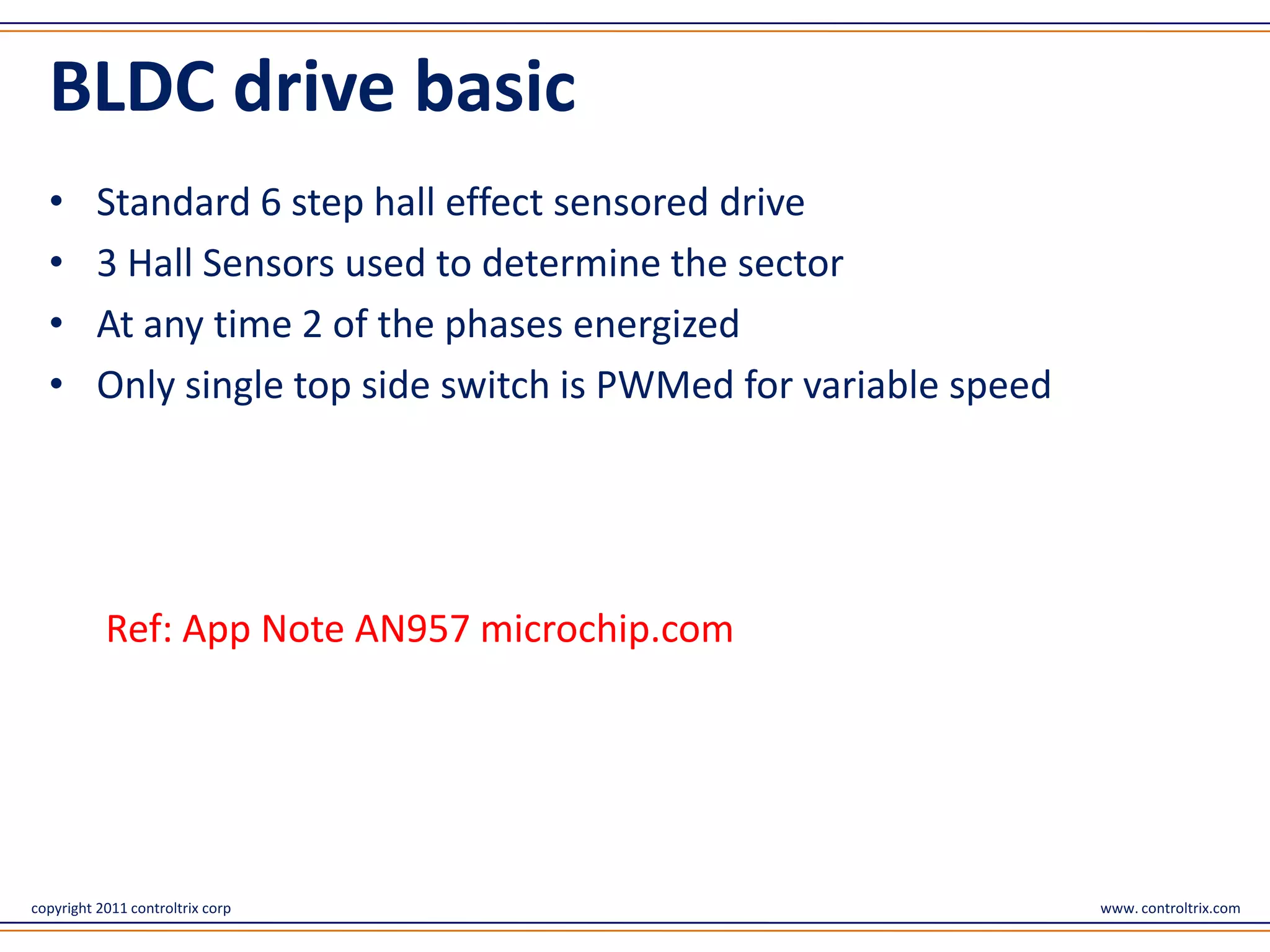
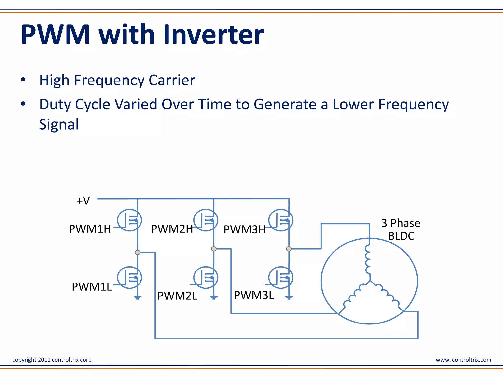
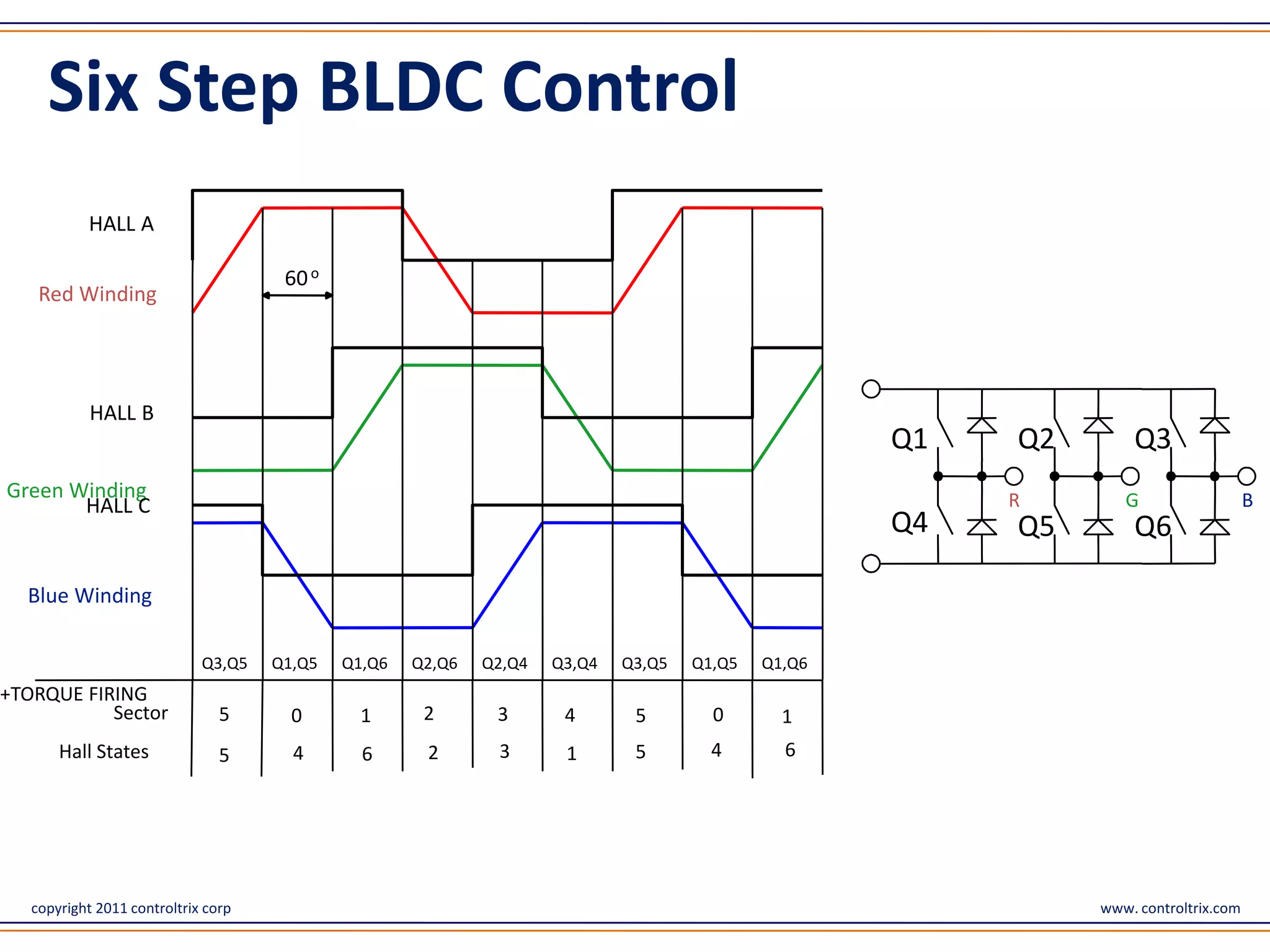
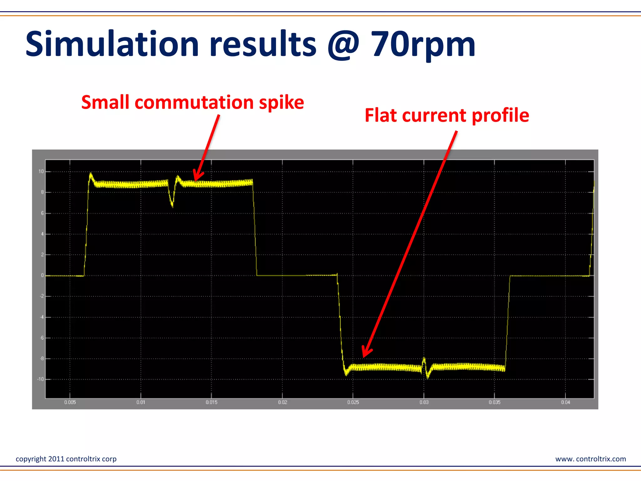
BLDC motor drive system
Improving efficiency a perspective on electric vehicles


                                        www.controltrix.com


copyright 2011 controltrix corp                               www. controltrix.com
BLDC drive basic
  •       Standard 6 step hall effect sensored drive
  •       3 Hall Sensors used to determine the sector
  •       At any time 2 of the phases energized
  •       Only single top side switch is PWMed for variable speed


           Ref: App Note AN957 microchip.com


copyright 2011 controltrix corp                                     www. controltrix.com
PWM with Inverter
   • High Frequency Carrier
   • Duty Cycle Varied Over Time to Generate a Lower Frequency
     Signal


                         +V

                      PWM1H       PWM2H             3 Phase
                                          PWM3H
                                                     BLDC


                       PWM1L
                                  PWM2L    PWM3L


copyright 2011 controltrix corp                               www. controltrix.com
Six Step BLDC Control
           HALL A

                                      60 o
    Red Winding


            HALL B
                                                                                                     Q1   Q2       Q3
Green Winding                                                                                             R       G                   B
       HALL C
                                                                                                     Q4   Q5       Q6

  Blue Winding

                             Q3,Q5   Q1,Q5   Q1,Q6   Q2,Q6   Q2,Q4   Q3,Q4   Q3,Q5   Q1,Q5   Q1,Q6
+TORQUE FIRING
           Sector               5      0       1      2       3       4       5        0       1
       Hall States              5      4       6      2       3       1       5        4       6


   copyright 2011 controltrix corp                                                                             www. controltrix.com
Electric Vehicle Specific
  •      250 W , 24 V, 12 A direct drive system
  •      350 rpm @
  •      80% drive +motor efficiency(baseline) @ 10A ,300 rpm
  •      Regenerative efficiency (3 bottom PWM) 0.70
  •      Regenerative braking by PWMing the 3 bottom switches
  •      Target use - Stop and go city traffic
  •      Limited Range ~50-70 km/charge
  •      Average Indian urban vehicle speed < 25 Km/hr
  •      Battery round trip efficiency 0.90


copyright 2011 controltrix corp                                 www. controltrix.com
Automobile standard
  •       Energy wasted in braking : Energy used in rolling = 3:2
  •       Indian urban braking losses much more (ratio = 2:1)
  •       Aerodynamic losses negligible at low urban speeds
  •       Rapid accelerating phase (hi torque / hi current)
  •       Large i2R losses and low output power (low speed)
  •         is even lower ~ 50 %
  •       e.g. Stop and go traffic conditions

  Ref: http://en.wikipedia.org/wiki/Fuel_economy_in_automobiles


copyright 2011 controltrix corp                                     www. controltrix.com
Example
  • 100 units from battery
  • 80 units converted to kinetic (
  • 26 lost in rolling
  • 54 remaining in vehicle KE
  • 54*0.7 = 37.8 returned back to battery
  • For next cycle 37.8*0.9 = 34 reusable
  • total usable energy over lifetime =
    100 + 34 + 34*0.34 + 34*0.34^2+….. = 100/(1-0.34) = 151
  • Figure of merit (FOM) = 151/100 = 1.51 (base line case)
  • FOM directly co relates to range and time between charging


copyright 2011 controltrix corp                             www. controltrix.com
Automobile standard..
  •           = 85% => FOM = 1.77=> +18% range
  •           = 90% => FOM = 1.95=> +29% range
  •           = 95% => FOM = 2.19=> +45% range

  Summary :
  • Small change in  large range change
  • Imperative to explore ways to improve


copyright 2011 controltrix corp                  www. controltrix.com
Losses
  •       Most type of losses are related to current
  •       (Motor + inverter )Resistive losses
  •       Inverter Switching losses
  •       Motor magnetic losses
  •       To reduce losses reduce current !!


copyright 2011 controltrix corp                        www. controltrix.com
Other sources
  Non trapezoidal current shape

            •       Spikes, kinks on commutation instants
            •       Motor dynamics
            •       Increases RMS current
            •       More losses

            • Commutation pattern and duty control addresses this problem


copyright 2011 controltrix corp                                  www. controltrix.com
Other sources.
  Motor inductance

            •       Current lags voltage
            •       Derates motor constant @ higher speed
            •       Increase in current for given torque
            •       Increase in losses for given torque ~ 12%
            •       Proper dynamic phase advance removes this problem


copyright 2011 controltrix corp                                         www. controltrix.com
Other sources.
  Asynchronous vs. synchronous switching

  Asynchronous
     • Bottom diode conducts during off time
     • Diode conduction losses are higher

  Synchronous
     • Complementary mode PWM
     • Bottom MOSFET conducts during off time
            • Loss reduction ~ 10 W


copyright 2011 controltrix corp                 www. controltrix.com
Commutation kickback current
  Commutation kink due to finite inductance in current waveform…
  leads to increase in RMS current and thus losses


                                                                 Commutaion kickback
                                                                 current
                                  Rising gradual slopes   Kink
copyright 2011 controltrix corp                                               www. controltrix.com
Other sources..
  Regeneration strategy

  • 3 bottom switches are PWMed
     • Large Diode conduction losses ~24W
     • Non ideal current waveshape (with peaks)

  • 2 leg switching
     • Low losses ~ 10% efficiency gain
     • Slightly more logic/math computation
     • Proper implementation else noise, current spikes

            Not to be confused with phase reversal (causes enormous
            jerk, potentially destructive)

copyright 2011 controltrix corp                                   www. controltrix.com
Energy budget
  •       100 units supplied by battery
  •       80 converted to kinetic energy
  •       20 lost due to current flow
  •       10% reduction in current reduces losses(I2R) by 20 %
  •       Only 16 are now lost
  •         becomes 84%


copyright 2011 controltrix corp                                  www. controltrix.com
Strategies and efficiency
   Motoring + Regeneration               gain

   Synchronous switching                 +1%
   Torque mode or current mode control   +2%

   Proper calculated phase advance       +2%
   Reduce commutation kinks and spikes   +1%

   Only Regeneration

   Proper 2 leg regenerative braking     +10%


copyright 2011 controltrix corp                 www. controltrix.com
Energy budget
   Motoring + Regeneration        gain

   Motoring efficiency            86

   Regenerating efficiency        86

   FOM                            1.79
   Range gain on baseline         +18.9%


copyright 2011 controltrix corp            www. controltrix.com
Simulation results @ 300 rpm
  Motoring / Regeneration current wave   Rapid rise and fall of
  shape                                  current


copyright 2011 controltrix corp                             www. controltrix.com
Simulation results @ 70rpm
                    Small commutation spike
                                              Flat current profile


copyright 2011 controltrix corp                                      www. controltrix.com
Reliability issues
  • Hall Sensor State change use change notification Interrupt (CNI)

  • Improper Hall state determination leads to improper commutation

  • Cause of possible accidents

  • Controller failure/ reliability problems

  • PWM switching causes noise causes spurious CNI  failure


copyright 2011 controltrix corp                                www. controltrix.com
Improving Reliability
  • Do not use CNI poll Hall IO lines

  • Polling triggered using ADC variable trigger

  • Trigger away from PWM switching instants

  • Improves reliability many fold

  • Cycle by cycle current limiting


copyright 2011 controltrix corp                    www. controltrix.com
Thank You
                                  consulting@controltrix.com


copyright 2011 controltrix corp                                www. controltrix.com

Bldc motor drive system

  • 1.
    BLDC motor drivesystem Improving efficiency a perspective on electric vehicles www.controltrix.com copyright 2011 controltrix corp www. controltrix.com
  • 2.
    BLDC drive basic • Standard 6 step hall effect sensored drive • 3 Hall Sensors used to determine the sector • At any time 2 of the phases energized • Only single top side switch is PWMed for variable speed Ref: App Note AN957 microchip.com copyright 2011 controltrix corp www. controltrix.com
  • 3.
    PWM with Inverter • High Frequency Carrier • Duty Cycle Varied Over Time to Generate a Lower Frequency Signal +V PWM1H PWM2H 3 Phase PWM3H BLDC PWM1L PWM2L PWM3L copyright 2011 controltrix corp www. controltrix.com
  • 4.
    Six Step BLDCControl HALL A 60 o Red Winding HALL B Q1 Q2 Q3 Green Winding R G B HALL C Q4 Q5 Q6 Blue Winding Q3,Q5 Q1,Q5 Q1,Q6 Q2,Q6 Q2,Q4 Q3,Q4 Q3,Q5 Q1,Q5 Q1,Q6 +TORQUE FIRING Sector 5 0 1 2 3 4 5 0 1 Hall States 5 4 6 2 3 1 5 4 6 copyright 2011 controltrix corp www. controltrix.com
  • 5.
    Electric Vehicle Specific • 250 W , 24 V, 12 A direct drive system • 350 rpm @ • 80% drive +motor efficiency(baseline) @ 10A ,300 rpm • Regenerative efficiency (3 bottom PWM) 0.70 • Regenerative braking by PWMing the 3 bottom switches • Target use - Stop and go city traffic • Limited Range ~50-70 km/charge • Average Indian urban vehicle speed < 25 Km/hr • Battery round trip efficiency 0.90 copyright 2011 controltrix corp www. controltrix.com
  • 6.
    Automobile standard • Energy wasted in braking : Energy used in rolling = 3:2 • Indian urban braking losses much more (ratio = 2:1) • Aerodynamic losses negligible at low urban speeds • Rapid accelerating phase (hi torque / hi current) • Large i2R losses and low output power (low speed) • is even lower ~ 50 % • e.g. Stop and go traffic conditions Ref: http://en.wikipedia.org/wiki/Fuel_economy_in_automobiles copyright 2011 controltrix corp www. controltrix.com
  • 7.
    Example •100 units from battery • 80 units converted to kinetic ( • 26 lost in rolling • 54 remaining in vehicle KE • 54*0.7 = 37.8 returned back to battery • For next cycle 37.8*0.9 = 34 reusable • total usable energy over lifetime = 100 + 34 + 34*0.34 + 34*0.34^2+….. = 100/(1-0.34) = 151 • Figure of merit (FOM) = 151/100 = 1.51 (base line case) • FOM directly co relates to range and time between charging copyright 2011 controltrix corp www. controltrix.com
  • 8.
    Automobile standard.. • = 85% => FOM = 1.77=> +18% range • = 90% => FOM = 1.95=> +29% range • = 95% => FOM = 2.19=> +45% range Summary : • Small change in  large range change • Imperative to explore ways to improve copyright 2011 controltrix corp www. controltrix.com
  • 9.
    Losses • Most type of losses are related to current • (Motor + inverter )Resistive losses • Inverter Switching losses • Motor magnetic losses • To reduce losses reduce current !! copyright 2011 controltrix corp www. controltrix.com
  • 10.
    Other sources Non trapezoidal current shape • Spikes, kinks on commutation instants • Motor dynamics • Increases RMS current • More losses • Commutation pattern and duty control addresses this problem copyright 2011 controltrix corp www. controltrix.com
  • 11.
    Other sources. Motor inductance • Current lags voltage • Derates motor constant @ higher speed • Increase in current for given torque • Increase in losses for given torque ~ 12% • Proper dynamic phase advance removes this problem copyright 2011 controltrix corp www. controltrix.com
  • 12.
    Other sources. Asynchronous vs. synchronous switching Asynchronous • Bottom diode conducts during off time • Diode conduction losses are higher Synchronous • Complementary mode PWM • Bottom MOSFET conducts during off time • Loss reduction ~ 10 W copyright 2011 controltrix corp www. controltrix.com
  • 13.
    Commutation kickback current Commutation kink due to finite inductance in current waveform… leads to increase in RMS current and thus losses Commutaion kickback current Rising gradual slopes Kink copyright 2011 controltrix corp www. controltrix.com
  • 14.
    Other sources.. Regeneration strategy • 3 bottom switches are PWMed • Large Diode conduction losses ~24W • Non ideal current waveshape (with peaks) • 2 leg switching • Low losses ~ 10% efficiency gain • Slightly more logic/math computation • Proper implementation else noise, current spikes Not to be confused with phase reversal (causes enormous jerk, potentially destructive) copyright 2011 controltrix corp www. controltrix.com
  • 15.
    Energy budget • 100 units supplied by battery • 80 converted to kinetic energy • 20 lost due to current flow • 10% reduction in current reduces losses(I2R) by 20 % • Only 16 are now lost • becomes 84% copyright 2011 controltrix corp www. controltrix.com
  • 16.
    Strategies and efficiency Motoring + Regeneration gain Synchronous switching +1% Torque mode or current mode control +2% Proper calculated phase advance +2% Reduce commutation kinks and spikes +1% Only Regeneration Proper 2 leg regenerative braking +10% copyright 2011 controltrix corp www. controltrix.com
  • 17.
    Energy budget Motoring + Regeneration gain Motoring efficiency 86 Regenerating efficiency 86 FOM 1.79 Range gain on baseline +18.9% copyright 2011 controltrix corp www. controltrix.com
  • 18.
    Simulation results @300 rpm Motoring / Regeneration current wave Rapid rise and fall of shape current copyright 2011 controltrix corp www. controltrix.com
  • 19.
    Simulation results @70rpm Small commutation spike Flat current profile copyright 2011 controltrix corp www. controltrix.com
  • 20.
    Reliability issues • Hall Sensor State change use change notification Interrupt (CNI) • Improper Hall state determination leads to improper commutation • Cause of possible accidents • Controller failure/ reliability problems • PWM switching causes noise causes spurious CNI  failure copyright 2011 controltrix corp www. controltrix.com
  • 21.
    Improving Reliability • Do not use CNI poll Hall IO lines • Polling triggered using ADC variable trigger • Trigger away from PWM switching instants • Improves reliability many fold • Cycle by cycle current limiting copyright 2011 controltrix corp www. controltrix.com
  • 22.
    Thank You consulting@controltrix.com copyright 2011 controltrix corp www. controltrix.com