This document describes a thesis submitted by five students for their Bachelor of Engineering degree. The thesis is about designing and testing a zero voltage transition synchronous buck converter. Key points:
- The students designed a high frequency synchronous buck converter that operates at 200 kHz with an efficiency over 95% for low output voltages.
- It uses soft switching techniques like zero voltage switching and zero current switching to reduce switching losses in the power devices and improve efficiency.
- An auxiliary circuit with an inductor and capacitor allows the main switch to turn on under zero voltage switching. The auxiliary switch turns off under zero current switching.
- MOSFETs are used as the power switches and a TL494 PWM IC generates the 200
This document discusses principles and methods for sizing photovoltaic (PV) systems. It describes how utility-interactive PV systems are sized based on inverter requirements, with the PV array sized to the inverter's maximum power rating. Stand-alone PV systems must balance energy supply and demand, with the battery and PV array sized to meet the average daily load during the critical design month with lowest sunlight. Proper load analysis and system sizing are important to achieve high system availability from a stand-alone PV system.
This chapter examines the economic impact of transmission networks on their users. It discusses how transmission networks can affect system operation costs through losses and constraints. Losses occur as some power is lost as heat during transmission, requiring more generation. Constraints may require more costly generation if cheaper options violate transmission limits. The chapter also notes the importance of location - both in determining the impact of individual users on losses and constraints, and in allocating network costs to users based on their contributing locations.
The document is a project report submitted by four students for their B.Tech degree in Electrical Engineering. It discusses the design of an Arduino-based power inverter using MATLAB. The objective is to design a low-cost inverter compared to commercially available options. The report includes chapters on the history of inverters, components used including Arduino, MOSFETs, transformers and batteries. It also discusses simulations of inverter circuits and the design of the Arduino-based inverter circuit.
A digital storage oscilloscope is a common laboratory instrument that provides accurate time and amplitude measurements of voltage signals over a wide frequency range. It uses a cathode-ray tube to display signal waveforms and stores the waveforms digitally, allowing repeated playback and analysis. The digital storage oscilloscope provides reliable, stable measurements and is easy to operate, making it a versatile general purpose tool in electronics laboratories.
The document discusses power bipolar junction transistors (BJTs). It notes that power BJTs have a vertically oriented four-layer structure to increase their cross-sectional area and allow for high voltage blocking and current carrying capacity. Key layers include a heavily doped emitter, moderately doped base, lightly doped collector drift region, and highly doped collector. The drift region increases the breakdown voltage but also increases resistance. Power BJTs are used in applications like switched mode power supplies, inverters, motor controllers due to their high power handling capability.
The document discusses the properties of an ideal transformer. It states that an ideal transformer is a lossless device with an input and output winding. It has infinite magnetic permeability and electrical resistivity, with flux confined to the core and negligible winding resistances. The relationships between the voltages and currents in the input and output windings are given by equations relating the turns ratio. An ideal transformer is used to couple a load to a power source by "reflecting" the load impedance to the primary winding.
A power quality monitoring system gathers and analyzes electricity measurement data to provide useful information. It allows plants to perform energy management, preventive maintenance, quality control, and save money. Power quality monitoring equipment includes digital fault recorders, smart relays, voltage recorders, in-plant power monitors, and special-purpose power quality equipment. These devices monitor voltage, current, and other measurements to detect issues like harmonics, sags, disturbances and optimize power quality and performance.
Index
Applications of Control System
Definition of Control System
Open Loop Control System
Applications of Open Loop Control System
Close Loop Control System
Applications of Close Loop Control System
IDEAL AND PRACTICAL TRANSFORMER, EQUIVALENT CIRCUIT OF TRANSFORMER|DAY5|BASIC...Prasant Kumar
#IDEAL_PRACTICAL_TRANSFORMER
#EQUIVALENT_CIRCUIT OF TRANSFORMER
#BASIC ELECTRICAL ENGINEERING
#IDEAL TRANSFORMER ON NO LOAD
#PRACTICAL TRANSFORMER ON LOAD
#ELECTRCL TRANSFORMER
#SINGLE PHASE TRANSFORMER
Link of all sessions are.
DAY 1 (Need/Definition)
https://youtu.be/BvaykFJ_NoE
DAY 2 (Working principle and Construction)
https://youtu.be/06rgxocihaM
DAY 3 (EMF equation and Turns Ratio)
https://youtu.be/g7e5xBPmv3Y
DAY 4 (Classification of Transformer)
https://youtu.be/6NP5L4MlvY4
DAY 5 ( Ideal and practical transformer on no load)
(Equivalent Transformer)
https://youtu.be/6LCLQC1p3lg
Three-phase systems have multiple voltages or currents that are displaced in time by 120 degrees. They provide advantages over single-phase systems like higher power capacity, self-starting motors, and more constant power output.
A 3-phase generator produces 3 voltages displaced by 120 degrees through its winding configuration. The voltages can be connected in either a star or delta configuration. In a star connection, the winding ends meet at a central neutral point. In a delta connection, the windings are connected in a closed loop.
Power in a 3-phase circuit can be measured using either 3 wattmeters connected to each phase, or 2 wattmeters connected across different phase combinations to calculate total power.
Power System Stability
Power system stability is the ability of an electric power
system, for a given initial operating condition, to regain a
state of operating equilibrium after being subjected to a
physical disturbance, with most system variables bounded
so that practically the entire system remains intact.
This document presents an overview of reactive power compensation. It defines reactive power compensation as managing reactive power to improve AC system performance. There are two main aspects: load compensation to increase power factor and voltage regulation, and voltage support to decrease voltage fluctuations. Several methods of reactive power compensation are discussed, including shunt compensation using capacitors and reactors, series compensation, static VAR compensators (SVCs), static compensators (STATCOMs), and synchronous condensers. SVC and STATCOM technologies are compared, with STATCOMs having advantages of smaller components, better control, and transient response.
Feedback amplifiers, Power Amplifiers, OscillatorsSwamy T N
This document provides an overview of analog circuits including feedback amplifiers, power amplifiers, and oscillators. It discusses the different types of feedback amplifiers including voltage, current, transconductance, and transresistance amplifiers. It also describes various classes of power amplifiers such as Class A, B, AB, and C and how their operating points, efficiencies, distortions, and applications differ. Additionally, it covers the basics of feedback including its properties and topologies as well as oscillators like phase shift and LC oscillators.
Thyristor is a four-layered semiconductor device that can conduct current in one direction when a gate signal is applied. It has the property of latching where it stays in the forward conducting state even after the removal of the gate signal. The document discusses the structure of a thyristor including the doped layers, its operating characteristics like turn on, turn off and static characteristics. It describes the transient behaviors during turn on and turn off and limitations during these processes. The document also covers parameters mentioned in thyristor datasheets and different types of thyristors like SCR, DIAC and TRIAC.
The document discusses unit commitment in power systems. Unit commitment involves determining which generating units to operate and when to operate them in order to meet the changing electricity demand at the lowest possible production cost while satisfying operational constraints. It describes the unit commitment problem and various constraints like minimum up/down times, ramp rates, reserve requirements, and start-up costs that make it more complex than economic dispatch. It provides a simple example to illustrate the concepts.
Speed control of dc motor conventional methods and solid state controlDr SOUNDIRARAJ N
This document discusses various methods for controlling the speed of DC motors, including both conventional and solid state methods. Conventional methods include flux control, armature voltage control, and the Ward-Leonard system for shunt and series motors. Solid state speed control uses power semiconductor switches like SCRs, MOSFETs, and IGBTs. Phase-controlled rectifier drives and chopper drives are described as two types of solid state DC motor drives. Specific circuit configurations are provided for single and three-phase half and fully controlled rectifier drives. Applications and advantages/disadvantages of the different speed control methods are also summarized.
The document discusses different types of sensors and transducers used to measure important process parameters such as flow, temperature, pressure, and level. It describes transducers as devices that convert one form of energy into another. It then provides details on various sensors used to measure temperature, including thermocouples, thermistors, RTDs, and pyrometers. It also discusses common pressure measurement techniques like manometric and elastic pressure transducers using devices like Bourdon tubes, bellows, and diaphragms.
The document discusses the working of a cycloconverter circuit. It contains 3 SCRs per phase arranged in groups of 3 that are responsible for the positive and negative alterations in the output voltage. There are a total of 18 SCRs required for the whole circuit, with the firing sequences of the SCRs in each phase group lagging the previous group by 120 degrees and 240 degrees. The average output voltage and frequency can be controlled by varying the firing angles of the SCRs and the sequence of SCR firing, respectively.
The document discusses the components and structure of an electric power system. It describes how power is generated at power stations and stepped up in voltage for transmission over long distances before being stepped down for distribution to consumers. The key components are generators, transformers, transmission lines, control equipment, and distribution systems. Power flows from generation through transmission and distribution before reaching ultimate consumers.
Vector control is a more advanced and precise method of controlling AC induction motors compared to scalar control. It involves transforming the motor currents and voltages into a rotating reference frame to obtain decoupled control similar to a DC motor. This allows for independent control of flux and torque for faster dynamic response and better performance than scalar control. The basic implementation of vector control uses Clarke and Park transformations to convert between stationary and rotating reference frames in the controller. It provides DC motor-like precision in speed and torque control of induction motors.
The Heffron-Phillips model is commonly used for small signal stability analysis of synchronous machines. It represents synchronous generators as having electrical and mechanical components. The model parameters are calculated using generator parameters and steady-state operating conditions. The Heffron-Phillips model has been extensively used to investigate low frequency oscillations in power systems and design power system stabilizers.
The document discusses measurement of resistance (R), inductance (L), and capacitance (C) parameters. It provides technical data on R, L, and C as well as information on industries that manufacture components related to R, L, and C including resistors, capacitors, and inductors. It also describes potential training programs on R, L, and C measurement and a mobile application for measuring R, L, and C wirelessly using a Bluetooth-enabled LCR meter.
POWER SYSTEM PLANNING AND DESIGN. DESIGN OF EHV TRANSMISSION LINES & BUNDLED ...Jobin Abraham
This document discusses the design of extra high voltage transmission lines and bundled conductors in EHV lines. It outlines the advantages of EHV lines such as reduced transmission losses and material requirements. However, it also notes disadvantages like increased corona losses and insulation needs. Key design considerations for EHV lines include the choice of operating voltage, grounding method, conductor selection, and insulator selection. For lines above 400kV, bundled conductors are used and the document discusses formulas for calculating the inductance, capacitance, surge impedance, and surge impedance loading to determine bundling requirements.
Transducers,Active Transducers and Passive TransducersAL- AMIN
Transducers are devices that convert one form of energy into another. They are used in a variety of applications like detecting muscle movement, measuring engine loads and knocks, converting temperature, pressure, and sound into electrical signals. Transducers are also used in antennas to convert electromagnetic waves to electrical signals. There are two main types: active transducers like thermocouples and photovoltaic cells convert non-electrical energy into electrical energy themselves, while passive transducers like strain gauges and differential transformers require an external force and convert non-electrical energy into electrical energy with help.
(1) The document describes an infrared plastic solar cell that uses nanotechnology to absorb invisible infrared rays from sunlight for power generation. (2) It consists of cadmium selenide nano rods bound with a polymer that allow it to detect infrared light and generate electrons and electron holes to produce a current. (3) The plastic solar cell is more efficient than traditional silicon solar cells, flexible, lightweight, and can generate power even on cloudy days by absorbing infrared rays.
This document provides an introduction to programmable logic controllers (PLCs). It covers PLC hardware inputs and outputs, the IEC 61131-3 programming languages, and ladder diagram programming. The full tutorial explains types and sizes of PLCs, discrete and analog I/O, and network I/O. It also discusses the IEC 61131-3 languages, and provides details on ladder diagram programming including contacts, coils, counters, timers, comparison instructions, arithmetic instructions, and sequencer instructions. The document concludes with sections on human-machine interfaces, derivations, technical references, questions, projects and experiments.
Naturally clamped zero current commutated soft-switching current-fed push–pul...LeMeniz Infotech
Naturally clamped zero current commutated soft-switching current-fed push–pull dcdc converter analysis, design, and experimental results
To Get this projects Call : 9566355386 / 99625 88976
Visit : www.lemenizinfotech.com / www.ieeemaster.com
Mail : projects@lemenizinfotech.com
JPEEE1440 Cascaded Two-Level Inverter-Based Multilevel STATCOM for High-Pow...chennaijp
We offer different types of eee projects at affordable price in Chennai. You can easily choose titles with abstract and also full base paper for your reference.
For more details:
http://jpinfotech.org/final-year-ieee-projects/2014-ieee-projects/eee-projects/
Este documento presenta la asignatura de Filosofía de la Ciencia. Explica que el 35% de la calificación proviene de trabajos en clase, el 30% de tareas, y el 35% de un examen. También define filosofía, ciencia, y filosofía de la ciencia. Finalmente, asigna a los estudiantes la tarea de escribir biografías resumidas de Sócrates, Platón, Aristóteles, Descartes, Galileo, Bill Gates y Steve Jobs.
This document discusses obesity in minority populations. It defines obesity as having a BMI of 30 or higher. Obesity is caused by decreased physical activity and increased consumption of high-fat, energy-dense foods. Obesity is associated with health issues like diabetes, cardiovascular disease, and cancer. Minority groups have higher obesity rates due to socioeconomic factors and face greater health risks. The document provides guidelines for exercise prescriptions to help reduce weight, including 30 minutes per day of moderate activity and strength training 2-3 days per week.
This document summarizes how a media production conformed to and challenged genre conventions of slasher horror films. It emulated the suave characteristics of Patrick Bateman but used a young black male protagonist instead of the usual white male. Gory murder scenes were simulated using costume makeup instead of real blood. Isolated killing locations from films like Halloween and Insidious 2 were also recreated to convey the victim's confinement and helplessness.
This document is a resume for M. Lee Walters, who has 27 years of experience in senior-level military and project management positions. Some of the key experiences listed include serving as Chief of Staff at the US Army Joint Readiness Training Center, directing operations and support at US Southern Command headquarters, and leading a humanitarian assistance team in Haiti. The resume emphasizes Walters' leadership abilities and experience managing large organizations, budgets, and training operations. Core competencies include leadership, operations management, strategic development, and communication skills.
Consumabili compatibili per Epson expression home xp-235 disponibili nel nostro magazzino. Trova prezzi toner Epson expression home xp-235 o cartucce Epson expression home xp-235. Dal 1996 importiamo, scegliamo e testiamo per Te i migliori consumabili compatibili per Epson expression home xp-235 presenti oggi nel mercato per qualita' e durata. Scegli quindi il tuo consumabile per Epson expression home xp-235 e stampa i tuoi documenti in alta qualita'.
This document is a record of achievement for Aijaz Shaikh completing an openSAP course on Rapid Deployment of SAP Solutions. It details that he scored the maximum 120 points, completing weekly assignments, and was in the top 5% of participants. It lists the course topics covered from January to March 2015 and is verified online.
This document is a business dissertation submitted by Enas Ali investigating the impact of the Body Shop's corporate social responsibility on consumer decision making and behavior. It includes an introduction outlining the research question and aims, a literature review on CSR and the Body Shop's CSR activities, a methodology section, findings from focus groups, and an analysis and conclusions section. The dissertation examines how the Body Shop's emphasis on CSR through initiatives like banning animal testing, fair trade, and environmental protection influences customers' purchasing decisions and loyalty to the brand.
A hybrid cascaded multilevel converter for battery 2Ki Tu
This document describes a hybrid cascaded multilevel converter proposed for use in electric vehicle battery energy management systems. The converter consists of half-bridge converters connected to each individual battery cell that can control whether the cell is connected to or bypassed from the circuit. All the half-bridges are cascaded to output a multi-level staircase voltage. An H-bridge converter then changes the direction of the DC bus voltages to generate AC voltages for driving the motor. The converter allows for independent control and balancing of each battery cell's state of charge while generating cleaner multilevel output voltages suitable for motor drives.
choreography and performers: Marta Bevilacqua and Leonardo Diana
music: Alva Noto, Laurie Anderson, Crookers, Helen Merrill, Pharrell Williams
light design: Fausto Bonvini
costumes: Lucia Castellana
production: Versiliadanza, Compagnia Arearea
in collaboration with: Amat and Civitanova Danza per Civitanova Casa della Danza, Armunia Castello
Pasquini/Festival Inequilibrio – Castiglioncello, Lo Studio – Udine, Teatro Cantiere Florida/FLOW-residenze creative - Florence
This document provides a list of 57 technical papers published between 2010-2013 related to electrical engineering topics like power electronics, renewable energy, and control systems. It includes the paper titles and their respective years of publication. Contact information is also provided to inquire about further details.
Review of Step down Converter with Efficient ZVS OperationIJRST Journal
This paper presents the review of step down converter with efficient ZVS operation. The designed buck converter uses ZCS technique and the function is realized so that the power form is converted from 12V DC 5V DC (1A). A detailed analysis of zero current switching buck converters is performed and a mathematical analysis of the mode of operation is also presented. In order to reduce the switching losses in associated with conventional converters; resonant inductor and resonant capacitor (LC resonant circuit) is applied which helps to turn on-off the switch at zero current. The dc-dc buck converter receives the energy from the input source, when the switch is turned-on. The buck–buck converters have characteristics that warrant a more detailed study. The buck converters under discontinuous conduction mode /continuous conduction mode boundary.
A plan for new sales leaders. What to do in their first 75 days in their new position? An easy step by step guide. The first 25 days is to understand the current state of the sales team, next 25 days is about developing a GTM strategy followed by the next 25 days of implementation.
This document discusses the performance analysis of a three-phase four-wire shunt active power filter (SAPF). It first introduces power quality issues caused by nonlinear loads and defines active power filters as emerging devices that can effectively diminish harmonic pollution. It then presents the mathematical model of a SAPF using instantaneous reactive power theory. The performance of a three-phase four-wire SAPF is analyzed using proportional-integral (PI) and proportional-integral-derivative (PID) controllers. Simulation results in MATLAB verify the SAPF can compensate for harmonics and reactive power when controlled by PI and PID controllers.
Científicos europeos observaron por primera vez un puente entre dos estrellas masivas en la Nebulosa de la Tarántula que comparten el 30% de su materia y están apenas separadas por un día luz, lo que indica que eventualmente se fusionarán en una sola estrella gigante e incluso podrían explotar formando un agujero negro.
Las bacterias se comunican entre sí mediante impulsos eléctricos de forma similar a las neuronas. Un estudio descubrió que las bacterias Bacillus subtilis transmiten señales de estrés a través de cambios en el potencial de la membrana celular para coordinar los niveles de crecimiento en la colonia. Esta comunicación bacteriana lenta pero efectiva podría explicar el origen del sistema nervioso y proporcionar información sobre trastornos cerebrales.
A novel single switch resonant power converterSameer Kasba
This deals with the novel single-switch resonant power converter for renewable energy generation applications. This circuit topology integrates a novel single switch resonant inverter with zero-voltage-switching (ZVS) with an energyblocking diode with zero-current-switching (ZCS).
1) HVDC transmission was first developed in the late 19th century by Rene Thury. Early systems used DC series generators and mechanical converters.
2) HVDC became more viable with the development of mercury arc valves in the 1950s and thyristor valves in the 1960s, allowing more efficient conversion between AC and DC.
3) HVDC is preferable to HVAC for long distance bulk power transmission, asynchronous connections, offshore wind connections, and other applications where HVDC has technical advantages over HVAC. Key components of HVDC systems include converters, smoothing reactors, filters, and the DC transmission line.
This document analyzes and compares four different isolated DC-DC converter topologies for use in a solar-powered laptop charger: forward converter, full-bridge buck converter, half-bridge converter, and push-pull converter. It discusses the operating principles, stress factors, advantages, and disadvantages of each topology. The half-bridge converter is selected for its relatively low component stresses and simplicity of design compared to the other options. Detailed design of the magnetic, filter, and control components for the half-bridge converter is then presented.
System _ Technik _ Electronic LAB _ Semiconductor Components (2023).pdfislamsharawneh
This document provides instructions for conducting experiments on semiconductor components. It introduces rectifier diodes and discusses the effect of the p-n junction, showing that diodes allow current to pass in one direction but block it in the other. The document also compares the characteristics of diodes made from different semiconductor materials like silicon, germanium, and gallium arsenide. It provides detailed procedures for setting up circuits and measuring the I-V curves of each type of diode. The remaining sections cover other semiconductor components like Zener diodes, transistors, FETs, and thyristors.
This document discusses digital control applications for power electronics circuits. It notes that power electronics and discrete time systems have been closely related since the beginning due to the sampled and periodic nature of switching power supplies. Research has focused on implementing analog controllers like current and voltage loops using digital signal processors or microcontrollers, and more advanced approaches using custom integrated digital controllers. It anticipates that power devices and control logic may eventually be integrated on the same semiconductor die, further merging power electronics and digital control design methods. The document serves as an introduction to the topics that will be covered in the book.
This document provides an introduction to digital control applications in power electronics. It discusses how modern power electronics relies on digital control techniques and discrete time system theory. The trends toward increased digitization and integration are driving more widespread use of digital control. The book will use a single-phase voltage source inverter as a case study to illustrate different digital control techniques, including digital pulse width modulation, current control loops, voltage control loops, and extensions to three-phase inverters. It aims to provide basic knowledge of digital control of power converters and stimulate further research at the intersection of power electronics and discrete time control theory.
This document presents the final report for a power inverter circuit designed by three students. It describes the various components of the circuit including a boost converter, pulse width modulator, full-bridge, oscillator, and output filter. It discusses the design specifications, operation of each component, simulation and experimental results, efficiency calculations, and proposed optimizations. The power inverter is designed to convert a DC input voltage of 8-9V to a 30Vpp sine wave AC output with over 85% efficiency.
The document describes a student project report on closed loop voltage control of a DC-DC buck converter. It includes simulations and analysis of a buck converter circuit to generate a stable 5V output from a 12V input. The project involves designing the buck converter circuit, implementing pulse width modulation control, and developing a compensator for stable voltage regulation in the closed loop control system. Simulation results showing voltage control of the buck converter using PID compensation are presented.
This document describes a thesis submitted by Vishal K Gawade and Aayush Garg for their Bachelor's degree. The thesis focuses on modeling and simulation of induction motors and wind turbines. It provides background on vector control of induction motors and describes the mathematical modeling of induction motors. It also covers topics related to wind turbine design such as blade element momentum theory and pitch control. The document includes MATLAB code examples and Simulink models developed as part of the thesis work.
This document analyzes the performance of short, medium, and long transmission lines. It discusses how different loads affect the efficiency, voltage regulation, and power factor of short and medium lines. It also examines how connecting transmission lines in series or parallel impacts performance. The document explores how shunt and series compensation can be used to improve transmission line characteristics. Finally, it discusses methods for improving power factor, such as using static capacitors, and how circuit parameters are determined for different transmission line types.
This document is the user's guide for the ALTIVAR® 11 adjustable speed drive controllers. It provides information on technical specifications, installation, wiring, programming, maintenance and troubleshooting. The guide covers the North American, European and Asian product ranges which are used to control three-phase asynchronous motors from 0.25 to 3 hp and 208/230/240 V single-phase power. It contains safety warnings and instructions on mounting, electrical connections, programming parameters and fault diagnosis.
This document is the user's guide for the ALTIVAR® 11 adjustable speed drive controllers. It provides information on technical specifications, installation, wiring, programming, maintenance and troubleshooting of the drive controllers. The guide covers the North American, European and Asian product ranges and is intended to help qualified personnel safely install, operate and maintain the variable speed drives. Safety warnings are included and personnel are instructed to verify safe voltage levels before servicing the equipment.
This document provides an overview of the Emus BMS system, including its components, functionality, installation, configuration, and maintenance. The main components are the control unit, cell modules, current sensor, cell communication adapters, and software. Key functions include cell monitoring, current measurement, state of charge estimation, charging control, protections, temperature control, and communication with external devices. The document outlines how to install, configure, and maintain the various aspects of the BMS system.
Petroleum Refining Operator Resume Examples For 2022https://www.livecareer.com › ... › Production
Refining Operator with a strong work ethic and dedication seeking to obtain a position in which my knowledge and experienced can be fully utilized. Core ...
You visited this page on 14/9/22.
Refinery Operator Resume Example Bunge - LiveCareerhttps://www.livecareer.com › Resume Search
Team-oriented Refinery Operator focused on increasing production, minimizing equipment downtime and costs and maximizing overall plant efficiency. Meticulous ...
This document describes the design of a real-time standalone system for controlling load resonant inverters using a TMS320F28335 digital signal processor (DSP). It discusses implementing a digital control algorithm optimized in embedded C language. The algorithm is experimentally evaluated on a load resonant inverter prototype for an induction heating system. Sections cover literature review on induction heating and switched mode power supplies, the control algorithm mathematical model and software model, implementation details including hardware/software components and experimental setups, simulation and real-time results, and conclusions.
This document provides information on STM32F100x4, STM32F100x6, STM32F100x8, and STM32F100xB microcontrollers. It describes their key features such as an ARM Cortex-M3 CPU, Flash memory ranging from 16 to 128KB, SRAM from 4 to 8KB, timers, ADC, DAC, communication interfaces, and low power modes. It also provides detailed specifications on electrical parameters, pinouts, memory mapping, and packaging information.
This document provides information on the STM32F103x8 and STM32F103xB microcontrollers. It includes specifications for the ARM Cortex-M3 CPU core, memory features including 64 or 128 KB of flash and 20 KB of SRAM, peripherals such as timers, communication interfaces, ADC, and GPIO pins. It also provides pinout diagrams, electrical characteristics, and package information for various package types including VFQFPN36, UFQFPN48, and LFBGA100.
This document provides information on the STM32F103x8 and STM32F103xB microcontrollers. It includes specifications for the ARM Cortex-M3 CPU core, memory sizes, peripherals, and electrical characteristics. The MCUs have 64 or 128 KB of flash memory, 20 KB of SRAM, timers, ADCs, communication interfaces including USB, CAN and SPI, and are available in BGA and LQFP packages.
This document provides information about the Academic Press Series in Engineering, including:
- The series will include handbooks, textbooks, and professional reference books on cutting-edge engineering topics.
- It will also include single-authored books on state-of-the-art techniques and methods.
- The objective is to meet the needs of academic, industrial, and government engineers, as well as to provide instructional material for undergraduate and graduate teaching.
- The series editor is J. David Irwin, a well-known engineering educator who has been chairman of the electrical engineering department at Auburn University for 27 years.
This document is an instruction manual for the CT-2000V inverter produced by Cutes Corporation. It provides details on:
- Inspecting the inverter upon receiving
- Proper storage and installation procedures
- Wiring diagrams and specifications for connecting the main circuit and motor
- Recommendations for fitting an ACL to the power input side under certain conditions
The manual contains 9 chapters that cover topics such as keypad operation, parameter settings, control modes, protective functions, and serial communication protocols.
This thesis examines parameters identification of a permanent magnet DC motor. Chapter 1 introduces the research motivation and literature review on identification methods. Chapter 2 covers DC motor principles and common identification techniques like pseudo inverse, nonlinear least squares, and pattern search. Chapter 3 details the hardware design including MOSFET switches, PWM, and sensors. Chapter 4 presents experimentation, testing, and identification results using MATLAB/Simulink. The motor parameters are estimated using nonlinear least squares and pattern search methods. A GUI is designed for automation and student use. Chapter 5 provides conclusions and discusses future work such as improving accuracy and automating more of the process.
This technical document provides installation instructions for HF Series X-ray generators. It describes unpacking the generator cabinet and connecting it to line power. Detailed instructions are provided for routing cables within the cabinet and connecting high voltage cables, the X-ray tube, interconnection cables for various system components, and signal lines. Safety warnings are included and tools/equipment needed for installation and testing are listed. The document is intended to guide installation of the generator in the proper order to ensure safe and effective operation.
Similar to ZVS-Buck_converter-BE-Project_Report (20)
1. JSS Mahavidyapeetha
Sri Jayachamarajendra College of Engineering, Mysore 570 006
An Autonomous Institution Affiliated to
Visvesvaraya Technological University (VTU), Belgaum
Design and Testing of Zero Voltage Transition Synchronous
Buck Converter
Thesis submitted in partial fulfillment of the curriculum prescribed for the
award of the degree of Bachelor of Engineering in Electrical and
Electronics Engineering by
4JC11EE001 Aaron Elphinstone Wahlang
4JC11EE013 Boston Shullai
4JC11EE053 H Shreyas
4JC11EE065 Thirumalesh H S
4JC11EE067 Rajath Kashyap S
Under the Guidance of
R S Ananda Murthy
Associate Professor and Head
Department of E&EE, SJCE, Mysore
Sponsored by
LIFE Electronics, Bangalore
DEPT. OF ELECTRICAL & ELECTRONICS ENGINEERING
May, 2015
2. JSS Mahavidyapeetha
Sri Jayachamarajendra College of Engineering, Mysore 570 006
An Autonomous Institution Affiliated to
Visvesvaraya Technological University (VTU), Belgaum
Certificate
This is to certify that the work entitled Design and Testing of Zero Voltage Transi-
tion Synchronous Buck Converter is a bonafide work carried out by Aaron Elphinstone
Wahlang, Boston Shullai, H Shreyas, Thirumalesh H S and Rajath Kashyap S in partial ful-
fillment of the award of the degree of Bachelor of Engineering in Electrical and Electronics
Engineering of Visvesvaraya Technological University, Belgaum, during the year 2015. It
is certified that all corrections / suggestions indicated during CIE have been incorporated in
the report. The project report has been approved as it satisfies the academic requirements
in respect of the project work prescribed for the Bachelor of Engineering Degree.
Guide & Head of the Department
R S Ananda Murthy
Associate Professor
Department of E&EE
SJCE, Mysore 570 006
Date :
Place : Mysore
Examiners : 1._____________________________
2._____________________________
3._____________________________
3. Abstract
The objective of this project is to design and test a high frequency Zero Voltage Transition PWM
Synchronous buck converter which operates at low output voltage with an efficiency greater than
95%. In conventional PWM buck converters, the operating frequency of the switches is less than
50 kHz. This increases the size of filter capacitors and inductors, making the circuit bulky. During
switching there will be switching power losses in such converters due to presence of both volt-
age across and current through the devices, reducing the overall efficiency of the converter. In this
project, the switching losses in the power semiconducting devices is considerably reduced by adopt-
ing soft switching techniques and operating the switches at a high frequency of about 200 kHz. A
new passive auxiliary circuit consisting of a resonant inductor and a resonant capacitor is employed
across the main switch allowing it to turn ON under Zero Voltage Switching(ZVS). The auxiliary
switch is turned OFF under Zero Current Switching(ZCS). This is done to reduce the power losses
in the main switch and the auxiliary switch during switching transitions.
In order to maintain continuous load current, a freewheeling switch is employed in the output
circuit. The power loss in this switch is reduced by turning it ON in ZVS mode. MOSFETs(IRFZ44)
are used as power semiconducting switches in this project. For triggering the MOSFETs, TL494
PWM Control IC is used to generate the required PWM signal at a high frequency of about 200
kHz. The switches are operated at higher frequencies to reduce the size of inductors and capacitors
used in the circuit so that the overall size of the circuit is reduced. This project finds its applications
in the field of low voltage power supply in embedded systems, battery charging, laptops, mobiles,
etc, where battery backup is the key issue.
Keywords :
High Frequency, Buck Converter, Soft Switching, ZVS(Zero Voltage Switching) , ZCS(Zero Cur-
rent Switching), PWM, MOSFETs(IRFZ44), TL494 IC.
4. Acknowledgement
Firstly, we would like to thank our guide and mentor Sri R S Ananda Murthy for all of his help
to complete this project. His guidance gave shape and structure to our work. Also, his teaching
greatly improved our knowledge in the field of Power Electronics. We truly appreciate all of his
time and help. We would also like to thank Sri Ramesh Kumthekar and Sri M C Ganapathy of LIFE
Electronics, Bangalore for providing us the electronic components required to complete this project.
ii
10. Nomenclature
Co Filter Capacitance
Cr Resonant Capacitance
f Switching Frequency
fosc Oscillator Frequency
k Duty cycle
Lo Filter Inductance
Lr Resonant Inductance
T Switching time period
Va Average output voltage
Vi Input Voltage
Vor RMS Output Voltage
MOSFET Metal Oxide Semiconductor Field Effect Transistor
PWM Pulse Width Modulation
S Main Switch
S1 Auxiliary Switch
S2 Freewheeling Switch
ZCS Zero Current Switching
ZVS Zero Voltage Switching
viii
11. Chapter 1
Introduction
1.1 Brief Introduction to Power Electronics
Electrical energy demands are ever-increasing in order to improve the standard of living. Power
electronics is the technology associated with efficient conversion and control of electric power by
using power semiconductor devices. It aids in efficient utilization of electrical energy. Power elec-
tronics encompasses the use of electronic components, the application of circuit theory and design
techniques, and the development of analytical tools toward efficient electronic conversion, control,
and conditioning of electric power. Definition given by IEEE Power Electronics Society .
A basic Power Electronic system consists of the electrical energy source, power converter, con-
trol circuit, and electrical load. The electrical energy source provides the input energy and the load
uses that energy to perform the desired task. The load can be anything from a motor to a micropro-
cessor or a combination of electrical and electronic components.
Electrical
Energy
Source
Electrical
Load
Power
Electronic
Circuit
Control
Circuit
Figure 1.1: Block Diagram of Power Electronic System
Because of the increased advantages in the field of Power Electronics, it is extensively being
used in industrial automation, energy conservation and environmental pollution control. Also the
efficiency of Power Electronic devices are increasing along with a reduction in their cost. As a
result, its applications are ever increasing in industrial, commercial, residential, utility, aerospace
1
12. Chapter 1. Introduction 2
and military systems, etc. Modern industrial processes and energy systems benefit tremendously in
productivity and quality enhancement with the help of Power Electronics. Even though these have
a relatively higher initial investment, the energy saved in the long run provides adequate economic
benefits to the user. There is also the benefit of controlling environmental pollution because of
reduced power losses.
1.2 Objective of the Project
The objective of this project is to design and test a high frequency Zero Voltage Transition PWM
Synchronous Buck converter which operates at low output voltage with an efficiency greater than
95%. The switching losses in the power semiconducting devices are to be reduced by adopting soft
switching techniques. The switches are operated at a high frequency of about 200 kHz. As a result,
the sizes of filter capacitor and inductor used in the power circuit are reduced, thus increasing the
power density of the converter.
13. Chapter 2
DC-DC Converters
2.1 Introduction
In many industrial applications, fixed voltage dc sources have to be converted into variable voltage
dc sources. This can be accomplished by using a dc-dc converter or a chopper. It can be considered
as a dc equivalent to an ac transformer with a continuously variable turns ratio. Like a transformer,
it can be used to step down or step up a dc voltage source.
DC converters find applications in various fields. They can be used for traction control of motor
in electric automobiles, trolley cars, mine haulers, etc. They provide smooth acceleration control,
high efficiency and fast dynamic response. They can also be used in regenerative breaking of dc
motors to return energy back into the supply, and this feature results in energy savings for trans-
portation systems with frequent stops. DC converters are used in dc voltage regulators and are
also used in conjunction with an inductor to generate a dc current source, especially for the current
source inverter.
2.2 Principle of Step-Down Operation
i
Figure 2.1: Circuit for basic step-down operation
The basic principle of step down operation can be explained by the circuit shown in Figure 2.1.
Vi is the input supply voltage. S is the converter switch. The converter switch can be implemented
3
14. Chapter 2. DC-DC Converters 4
by using a power Bipolar Junction Transistor (BJT), power Metal Oxide Semiconductor Field-Effect
Transistor (MOSFET), Gate Turn Off Thyristor (GTO) or Insulated Gate Bipolar Transistor (IGBT).
The practical switches have a finite ON state voltage drop ranging from 0.5 to 2 V. For simplicity,
assume a resistive load R. When switch S is closed for a time t1, the input voltage Vi appears across
the load. If the switch remains OFF for a time t2, the voltage across the load is zero. The waveform
for the output voltage and load current are shown in Figure 2.2
T
Figure 2.2: Waveforms for step down operation
The average output voltage is given by
Va =
1
T
ˆ t1
0
v0dt =
t1
T
·Vi = f·t1 ·Vi = k·Vi (2.1)
where,
T is the chopping period
k =
t1
T
is the duty cycle of chopper
f is the chopping frequency.
And the average load current is given by,
Ia =
Va
R
=
k ·Vi
R
(2.2)
The rms value of output voltage is found from
Vor =
1
T
kTˆ
0
v2
odt =
√
k ·Vi (2.3)
Assuming a lossless converter, the input power to the converter is the same as the output power
and is given by
Pi =
1
T
ˆ kT
0
v0·idt =
1
T
ˆ kT
0
v2
0
R
dt = k·
V2
i
R
(2.4)
15. Chapter 2. DC-DC Converters 5
The effective input resistance seen by the source is
Ri =
Vi
Ia
=
Vi
k ·Vi
R
=
R
k
(2.5)
which indicates that the converter makes the input resistance Ri as a variable resistance of
R
k
.
The duty cycle k can be varied from 0 to 1 by varying t1, T, or f. Therefore, the output voltage
Vo can be varied from 0 to Vi by controlling k, and the power flow can be controlled.
1. Constant-frequency operation: The converter, or switching, frequency f (or chopping period
T) is kept constant and the on-time t1 is varied. The width of the pulse is varied and this type
of control is known as pulse width modulation (PWM) control.
2. Variable-frequency operation: The chopping, or switching, frequency f is varied. Either on-
time t1or off-time t2 is kept constant. This is called frequency modulation. The frequency has
to be varied over a wide range to obtain the full output voltage range. This type of control
would generate harmonics at unpredictable frequencies and the filter design would be difficult.
2.3 Types of DC-DC Converter
There are four types of dc-dc converters.
1. Buck Converter
In a buck regulator the average output voltage Va is less than the input voltage Vi. It requires
only one transistor, is simple and has high efficiency greater than 90%. The
di
dt
of the load
current is limited by inductor L. However, the input current is discontinuous and a soothing
input filter is normally required. It provides one polarity of output voltage and unidirectional
output current.
2. Boost Converter
In a boost converter, the output voltage is greater than the input voltage. A boost regulator
can step up the output voltage without a transformer. Due to a single transistor it has a high
efficiency. The input current is continuous. However, a high peak current has to flow through
the power transistor. The output voltage is very sensitive to changes in duty cycle k and it
might be difficult to stabilize the regulator. The average output current is less than the average
inductor current by a factor of (1-k), and a much higher rms current would flow through the
filter capacitor, resulting in the use of a larger filter capacitor and a larger inductor than those
of a buck converter.
3. Buck-Boost Converter
A buck-boost converter provides an output voltage that may be less than or greater than the
input voltage. The output voltage polarity is opposite to that of the input voltage. It is also
known as an inverting regulator. The output voltage is reversed without the use of transformer.
It has a high efficiency.
16. Chapter 2. DC-DC Converters 6
4. Cuk Converter
The Cuk Converter provides an output voltage that is less than or greater than the input volt-
age, but the output voltage polarity is opposite that of the input voltage. It is based on the
capacitor energy transfer. As a result, the input current is continuous. The circuit has low
switching losses and has high efficiency.
2.4 Conventional Buck Converter and its Drawbacks
V0RC
L
D
s
Vi
VL
VD
iL
Figure 2.3: Conventional Buck Converter
As described earlier a conventional buck converter is used to obtain an output voltage which
is less than the supply voltage. In this day and age with the development of wireless portable
devices such as laptops, phones etc, a need arises to develop a power circuit which can supply a
power in the range of 3 - 3.5 V with an efficiency greater than 90 %. Conventional buck converters
consist of a dc supply voltage followed by a switch. The switch employed may be a Metal Oxide
Semiconductor Field Effect Transistor (MOSFET), Bipolar Junction Transistor (BJT), Gate Turn
Off (GTO) thyristor and Insulated Gate Bipolar Transistor (IGBT). These switches are employed
as they can be controlled to obtain the desired turn OFF and turn ON time. A diode is connected
in parallel with the filter circuit to provide a closed path for the current to flow through the load
even when the main switch is OFF thus conserving the magnetic energy stored in the inductor Lo.
The buck converter consist of an inductor and a capacitor which form the filter circuit. The filter
inductor circuit is used to reduce the ripples present in the output current.The filter capacitor is used
to reduce the ripple in the output voltage. The output voltage is measured across the resistor R.
The major drawback of conventional buck converters is that there is a high switching loss due
to which their efficiency is low. They cannot operate at high frequencies, thus increasing the sizes
of L and C used in the circuit. This makes the circuit bulky and affects its portability. Due to this
the power density of the conventional buck converter is low. Moreover, the circuit is affected by
switched mode spiking, ringing as well as EMI (Electro Magnetic Interference).
17. Chapter 3
Power Devices Switching Techniques
3.1 Hard Switching
Hard switching techniques are employed in conventional buck converters. Here, simultaneous con-
duction of current and voltage takes place causing significant switching losses, thus decreasing the
efficiency of the converter. Since switching frequency is directly proportional to switching losses, it
is kept low while employing hard switching techniques. Due to this, there is an increase in the size
of the inductors and capacitors used. The voltage and current stresses on the device also increase
which may lead to an increase in the temperature of the device, ultimately causing a breakdown.
Other problems faced in hard switching are switch mode spiking and ringing, EMI and gate driver
corruption.
When the switch is turned ON, the voltage across it decreases and the current flowing through
it increases resulting in some switching losses. Similarly, losses are incurred when the switch is
turned OFF, the current through the switch decreases and the voltage across its terminals increases.
Figure 3.1 shows the turn ON and turn OFF characteristics of a MOSFET employing hard switching
technique.
I
Switching losses due to transition between current and voltage
dsV d
Figure 3.1: Hard Switching Characteristics of a MOSFET
3.2 Soft Switching
Soft switching techniques can be used to minimize the switching losses and EMI. In this technique,
the device is turned ON or OFF when either the voltage or the current is zero. Due to this, the
7
18. Chapter 3. Power Devices Switching Techniques 8
product of voltage and current is zero resulting in zero power loss. As a result the switches can
be operated at higher frequencies. Thus, the size and weight of the capacitors and inductors used
are reduced. The size and weight of the device are also reduced because the requirement of heat
sinks is eliminated. Using this technique, it is possible to increase the efficiency of the converter
beyond 95%. The proposed converter employs MOSFETs as switching devices. Their low ON state
resistance is low which results in a lower ON state voltage drop. Also, they can operate at very high
frequencies. MOSFETs are triggered or turned ON by providing an input gate voltage VGS greater
than the threshold voltage VT , which is the minimum voltage required for a MOSFET to be turned
ON.
Figure 3.2 shows the turn ON and turn OFF characteristics of a MOSFET employing soft switch-
ing technique.
Id
ZVS ZCS
Vds
Figure 3.2: Soft Switching Characteristics of a MOSFET
3.3 Types of Soft Switching
Soft Switching can be classified into two types:
1. Zero Voltage Switching (ZVS)
2. Zero Current Switching (ZCS)
Zero Voltage Switching (ZVS)
In ZVS technique the switch is either turned ON or OFF after making the voltage across it drop to
zero.
Voltage curve
time
ZVS Switching
Conventional
ON
amplitude
Current curve
Figure 3.3: Zero Voltage Switching
19. Chapter 3. Power Devices Switching Techniques 9
In this technique, a capacitor and a diode are connected in parallel with the switch as shown in
figure 3.4.
GATE
DRAIN
SOURCE
+
-
V
GS
Figure 3.4: ZVS - Operation
1. Turn ON: The voltage across the switch is brought to zero before the gate voltage is applied.
This facilitates an ideal, zero loss turn ON of the switch.
2. Turn OFF: The presence of the parallel capacitor prevents a sudden rise in the voltage across
the switch once it is turned OFF. Thus, the parallel capacitor acts like a loss-less snubber,
facilitating a low loss turn OFF of the switch.
Zero Current Switching (ZCS)
In ZCS technique the semiconductor switch is turned ON or OFF only after the current flowing
through it is made zero.
Conventional
OFF
Current curve
Voltage curve
time
amplitude
ZCS Switching
Figure 3.5: Zero Current Switching
In this technique, an inductor and a diode are connected in series with the switch as shown in
figure 3.6.
20. Chapter 3. Power Devices Switching Techniques 10
GATE
DRAIN
SOURCE
V
GS
+
-
Figure 3.6: ZCS - Operation
1. Turn ON: The presence of the series inductor prevents a sudden rise in the current through the
switch once it is turned ON. Thus, the series inductor acts like a loss-less snubber, facilitating
a low loss turn ON of the switch.
2. Turn OFF: The current flowing through the switch is brought to zero before the gate voltage
is removed. This facilitates an ideal, zero loss turn OFF of the switch.
21. Chapter 4
Analysis and Design of Power Circuit
4.1 Circuit of ZVT Synchronous Buck Converter
The power circuit consists of a DC Voltage supply (battery, solar panel, etc), a load (battery charging,
embedded systems), 3 IRFZ44L MOSFETS ( Switches S1, S2, S), filter components( Lo, Co), an
BA159 HY Schottky diode and resonant components (Lr, Cr). Each MOSFET has an integrated body
diode. This diode is used to discharge the capacitance between the gate and source of the MOSFET
when it is turned OFF. It also makes the MOSFET a bidirectional switch. The filter components Lo
and Co are used to reduce ripple current and ripple voltage respectively. The presence of resonant
components Lr and Cr ensures that impedance is low under resonance, thus a higher current flows
through the load, which is suitable for higher current applications. The Schottky diode is used to
provide a path for capacitance Cr to discharge; normal diodes cannot be used as they cannot operate
at high frequencies. Switch S2 is turned ON in ZVS and turned OFF in ZCS. Switch S is turned ON
in ZVS. S1 is turned OFF in ZCS. The freewheeling switch S2 ensures that current flows through the
load even when the main switch S is OFF, thus conserving the magnetic energy stored in inductor
Lo. The auxiliary switch S1 provides a path for Cs to discharge. Only after this can the main switch
S be turned ON.
+
-
Cs
Lo
rL rC
Co
v
o
i
v
L
O
A
D
s1 2
s
s
DS
Figure 4.1: Power Circuit Diagram
11
22. Chapter 4. Analysis and Design of Power Circuit 12
4.2 Operating Modes and Analysis
The 8 modes of operation of the converter are explained with the help of the typical waveforms
given below. The characteristics of each parameter and their operation in each mode are explained.
The equations for each parameter have been derived.
Theoretical Waveforms
Theoretical waveforms include all the parameters of the converter such as the voltage across and
current through the individual switches(S, S1 and S2), resonant inductor (Lr) and resonant capacitor
(Cr). The waveforms are sketched for one switching cycle and aid in explaining all eight modes of
operation.
S
S1
S2
VS2
VS1
VS
VCr
iLr
iS2
iDS
iS
iS1
t6 t7 t8
t3 t5t4
Io
V
i
V
i
Io
V
i
V
i
Io
Io
t1 t2t0
Figure 4.2: Waveforms of different parameters of Synchronous Buck Converter
23. Chapter 4. Analysis and Design of Power Circuit 13
Modes of Operation
Assumptions made during analysis
• The output inductor, Lo is considered to be very large. As a result, it acts as a constant current
source of value Io.
• The converter is assumed to be a time invariant system.
Mode 1 ( t0, t1)
+
-
Lo
rL rC
Co
v
o
i
v
L
O
A
D
s1 2
s
Figure 4.3: Mode 1
Prior to t = t0, the body diode of S2 conducts. The main switch S and auxiliary switch S1 are
turned OFF . At t = t0, the auxiliary switch S1 is turned ON using ZCS as it is in series with the
resonant inductor Lr. The current through resonant inductor Lr and resonant capacitor Cr rise at the
same rate as the current flowing through S2 falls. Resonance occurs between Lr and Cr during this
mode. Values of Lr and Cr are chosen such that, the resonant frequency is close to the switching
frequency of the converter. The operation in this mode ends at t = t1, when ILr reaches Io and IS2 falls
to zero. As a result, the body diode of S2 stops conducting. The voltage and current expressions
which govern this circuit mode are given below:
ID = Io- ILr
Using KVL,
Vi
s
= ILr (s) {s·Lr +
1
s·Cr
} (4.1)
Vi
s
= Lr ·ILr (s){
s2 +(
1
√
Lr ·Cr
)2
s
} (4.2)
24. Chapter 4. Analysis and Design of Power Circuit 14
ILr (s) =
Vi
Lr
·
s
s2 +(
1
√
Lr ·Cr
)2
(4.3)
ILr (s) =
Vi
Lr
·
√
Lr·Cr
√
Lr·Cr
s2 +(
1
√
Lr·Cr
)2
(4.4)
ILr (s) =
Vi
Lr
Cr
·
1
√
Lr·Cr
s2 +(
1
√
Lr·Cr
)2
(4.5)
But, Z =
Lr
Cr
and ω =
1
√
Lr·Cr
Taking Inverse Laplace Transform,
iLr (t) =
Vi
Z
·sinωt (4.6)
For a time invariant system,
iLr (t-t0) =
Vi
Z
·sinω(t-t0) (4.7)
At t = t1,
iLr (t1 - t0) = Io (4.8)
iD(S2) = 0 (4.9)
Io =
Vi
Z
·sinω(t1 - t0) (4.10)
(t1 - t0) =
1
ω
·sin−1
(
Io ·Z
Vi
) (4.11)
VCr (t1 - t0) = VCr1 (4.12)
25. Chapter 4. Analysis and Design of Power Circuit 15
Mode 2 ( t1, t2 )
+
-
Lo
rL rC
Co
v
o
i
v
L
O
A
D
s1 2
s
Figure 4.4: Mode 2
In this mode Lr and Cr continue to resonate. At t1, the synchronous switch S2 is turned ON
under ZVS condition. When iLr reaches its maximum value i.e. iLr(max)
, switch S2 is turned OFF
under ZVS condition.
iS2 = iLr - Io (4.13)
Using KVL,
Vi = Lr ·
d
dt
iLr +
1
Cr
ˆ t
0
iLr dt + VCr1 (4.14)
In the s domain,
Vi
s
= Lr{s·ILr -Io} +
1
s·Cr
·ILr +
VCr1
s
(4.15)
ILr (s){s·ILr +
1
s·Cr
} =
Vi −VCr1
s
+ Io ·Lr (4.16)
Lr·ILr (s){
s2 +(
1
√
Lr·Cr
)2
s
} =
Vi −VCr1
s
+ Io ·Lr (4.17)
ILr (s) =
Vi −VCr1
s·Lr
·
s
s2 +(
1
√
Lr ·Cr
)2
+ Io ·
s
s2 +(
1
√
Lr ·Cr
)2
(4.18)
ILr (s) =
Vi −VCr1
Lr
Cr
·
1
√
Lr ·Cr
s2 +(
1
√
Lr ·Cr
)2
+ Io ·
s
s2 +(
1
√
Lr ·Cr
)2
(4.19)
Taking Inverse Laplace Transform,
iLr (t) =
Vi −VCr1
Z
·sinωt + Io ·cosωt (4.20)
26. Chapter 4. Analysis and Design of Power Circuit 16
iLr (t - t1) =
Vi −VCr1
Z
·sinω(t - t1) + Io ·cosω(t - t1) (4.21)
at t = t2,
iLr (t2-t1) = ILr(max)
(4.22)
t12 =
1
ω
tan−1
(
Vi −VCr1
Io ·Z
) (4.23)
VCr (t2-t1) = VCr2 (4.24)
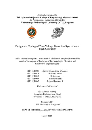
Mode 3 ( t2, t3)
+
-
Lo
rL rC
Co
v
o
i
v
L
O
A
D
1
s
s
Figure 4.5: Mode 3
At t2, iLr reaches its peak value iLr(max)
. Since the value of iLr is greater than load current Io, the
capacitor CS will be charged and discharged through the body diode of main switch S, which leads
to conduction of body diode. This mode ends when resonant current iLr falls to load current Io. So
current through body diode of main switch S becomes zero which turns OFF the body diode. At the
same time the main switch S is turned on under ZVS. The voltage and current expressions for this
mode are given below:
Using KVL,
Lr ·
d
dt
iLr +
1
Cr
ˆ t
0
iLr dt + VCr2 = 0 (4.25)
In the s domain,
Lr [s·ILr (s) - ILr(max)
] +
ILr (s)
s·Cr
+
VCr2
s
= 0 (4.26)
ILr (s)·Lr [
s2 +(
1
√
Lr ·Cr
)2
s
] = -
VCr2
s
+ Lr ·ILr(max)
(4.27)
27. Chapter 4. Analysis and Design of Power Circuit 17
ILr (s) = -
VCr2
s·Lr
·
s
s2 +(
1
√
Lr ·Cr
)2
+ ILr(max)
·
s
s2 +(
1
√
Lr ·Cr
)2
(4.28)
ILr (s) = -
VCr2
Lr
Cr
·
1
√
Lr ·Cr
s2 +(
1
√
Lr ·Cr
)2
+ ILr(max)
·
s
s2 +(
1
√
Lr ·Cr
)2
(4.29)
Taking Inverse Laplace Transform,
iLr (t) = -
VCr2
Z
·sinωt + ILr(max)
·cosωt (4.30)
iLr2 (t - t2) = -
VCr2
Z
·sinω(t-t2) + ILr(max)
·cosω(t - t2) (4.31)
at t = t3,
iLr (t3 - t2) = Io (4.32)
VCr (t3 - t2) = VCr3 (4.33)
(t3 - t2) =
1
ω
·[tan−1
(
ILr(max)
·Z
VCr2
) - sin−1
(Io)] (4.34)
Mode 4 ( t3, t4)
+
-
Lo
rL rC
Co
v
o
i
v
L
O
A
D
1
s
s
Figure 4.6: Mode 4
At t3, the main switch S is turned ON using ZVS. During this stage the growth rate of current
through main switch iS is determined by the resonance between Lr and Cr. The resonant process
continues in this mode and the current iLr continue to decrease. Switch S1can be turned OFF with
ZCS when iLr falls to zero. The voltage and current expressions for this mode are given below.
Using KVL,
Lr ·
d
dt
iLr +
1
Cr
ˆ t
0
iLr dt + VCr3 = 0 (4.35)
28. Chapter 4. Analysis and Design of Power Circuit 18
In the s domain,
Lr[s·ILr (s) - Io] +
1
s·Cr
(ILr (s)) +
VCr3
s
= 0 (4.36)
ILr (s)·Lr{
s2 +(
1
√
Lr ·Cr
)2
s
} = -
VCr3
s
+ Lr ·Io (4.37)
ILr (s) = -
VCr3
Lr
Cr
·
1
√
Lr ·Cr
s2 +(
1
√
Lr ·Cr
)2
+ Io ·
s
s2 +(
1
√
Lr ·Cr
)2
(4.38)
Taking Inverse Laplace Transform,
iLr (t) = -
VCr3
Z
·sinωt + Io cosωt (4.39)
iLr (t - t3) = -
VCr3
Z
·sinω(t - t3) + Io cosω(t - t3) (4.40)
at t = t4,
iLr = 0 (4.41)
tanω(t4 - t3) =
Io ·Z
VCr3
(4.42)
(t4- t3) =
1
ω
·tan−1
(
Io ·Z
VCr3
) (4.43)
VCr (t4) = VCr(max)
(4.44)
Mode 5 ( t4, t5)
+
-
Lo
rL rC
Co
v
o
i
v
L
O
A
D
1
s
s
Figure 4.7: Mode 5
At t4, the auxiliary switch S1 is turned OFF using ZCS. The body diode of S1 begins to conduct
due to resonant capacitor Cr which starts to discharge through the Schottky diode DS. The resonant
29. Chapter 4. Analysis and Design of Power Circuit 19
current iLr rises in the reverse direction, reaches a maximum negative value and increases to zero.
At this moment the body diode of S1 is turned OFF. The voltage and current equations for this mode
are given below.
Using KVL,
Lr ·
d
dt
iLr +
1
Cr
ˆ t
0
iLr dt + VCr(max)
= 0 (4.45)
In the s domain,
Lr[s·ILr (s) - 0] +
1
s·Cr
ILr (s) +
VCr(max)
s
= 0 (4.46)
ILr (s)·Lr·{
s2 +(
1
√
Lr ·Cr
)2
s
} = -
VCr(max)
s
(4.47)
ILr (s) = -
VCr(max)
s·Lr
·
s
s2 +(
1
√
Lr ·Cr
)2
(4.48)
ILr (s) = -
VCr(max)
Lr
Cr
·
1
√
Lr ·Cr
s2 +(
1
√
Lr ·Cr
)2
(4.49)
Taking Inverse Laplace Transform,
iLr (t) = -
VCr(max)
Z
sinωt (4.50)
iLr (t - t4) = -
VCr(max)
Z
sinω(t - t4) (4.51)
at t = t5,
iLr (t5) = 0 (4.52)
sinω(t5 - t4) = 0 (4.53)
(t5 - t4) =
π
ω
(4.54)
VCr (t5) = - VCr4 (4.55)
VCr4 = Vi (4.56)
30. Chapter 4. Analysis and Design of Power Circuit 20
Mode 6 ( t5, t6)
+
-
Lo
Co
v
o
i
v
L
O
A
D
s
Figure 4.8: Mode 6
Since the body diode of S1 has been turned OFF at t = t5, only the main switch S carries the load
current. There is no resonance in this mode and the circuit operation is identical to a conventional
PWM buck converter. The voltage and current equations for this mode are given below.
iS = Io (4.57)
iLr (t6) = 0 (4.58)
VCr (t6) = -VCr4 (4.59)
VCr4 = Vi (4.60)
Mode 7 ( t6, t7)
Lo
rC
Co o
v
L
O
A
D
DS
Figure 4.9: Mode 7
31. Chapter 4. Analysis and Design of Power Circuit 21
At t6, the main switch S is turned off using ZVS. The Schottky diode Ds starts conducting. The
resonant energy stored in the capacitor Cr starts discharging to the load through Schottky diode Ds.
This mode finishes when Cr is fully discharged. The equations that define this mode are given below.
VCr
s
=
1
s·Cr
·Io -
VCr4
s
(4.61)
Taking Inverse Laplace Transform,
VCr (t) =
1
Cr
ˆ t
0
Iodt - VCr4 (4.62)
VCr (t) =
1
Cr
·Io - VCr4 (4.63)
VCr (t-t4) = -VCr4 +
Io
Cr
·(t - t6) (4.64)
at t = t7,
VCr (t7) = 0 (4.65)
VCr4 =
Io
Cr
·(t7 - t6) (4.66)
Mode 8 ( t7, t8)
Lo
Co o
v
L
O
A
D
s2
Figure 4.10: Mode 8
At t7, the body diode of switch S2 is turned ON as soon as Cr is fully discharged and the Schottky
diode is turned OFF under ZVS. Dead time loss is negligibly small compared to the conventional
synchronous buck converter. During this mode, the converter operates like a conventional PWM
buck converter until the switch S1 is turned ON in the next switching cycle. The equation that
defines this mode are given below.
iS2 = Io (4.67)
32. Chapter 4. Analysis and Design of Power Circuit 22
4.3 Design Procedure
The resonant inductor, resonant capacitor and the delay time of the auxiliary switch S1 are the most
important components when designing the auxiliary circuit. The following parameters are taken
into consideration for the design of the proposed buck converter.
1. Delay time: The ON time of auxiliary switch S1 must be lesser than one tenth of the switching
period. In this period, the capacitor CS discharges fully such that the voltage across the main
switch S is zero at which point it is turned ON under ZVS.
TD <
1
10
TS (4.68)
2. Current Stress Factor: The current stress factor of the auxiliary switch is defined as
a =
ILrm
Iin(max)
(4.69)
Its value is desired to be as small as possible. This factor can be used for the selection of the
auxiliary switch S1as it determines how much extra current it can carry.
3. Resonant Capacitor (Cr): The value of the resonant capacitor is expressed as
Cr =
(a−1)2 ·Iin(max) ·TD
Vo ·[1+
π
2
·(a−1)]
(4.70)
4. Resonant Inductor (Lr): The value of the resonant inductor is expressed as
Lr =
Vo ·TD
Iin(max) ·[1+
π
2
·(a−1)]
(4.71)
4.4 Specifications of the Synchronous ZVS Buck Converter
1. Vo = 3.3 V
2. Io = 10 A
3. Vin = 15 V
4. Switching frequency: fs = 200 kHz
5. Resonant circuit :
Ls = 200 nH
Cr = 0.2673 µF
6. Filter circuit : (Assuming continuous conduction mode on the output side)
Lo = 4.29 µH (ripple current being 30% of Io ),
Co = 28.41 µF (ripple voltage being 2% of Vo )
7. Capacitor value across main switch S : Cs = 0.05 nF
33. Chapter 4. Analysis and Design of Power Circuit 23
Given below are the photographs of the power circuit:
Figure 4.11: Power Circuit View 1
Figure 4.12: Power Circuit View 2
34. Chapter 4. Analysis and Design of Power Circuit 24
4.5 Ratings of Power Devices
IRFZ44N MOSFET
Absolute Maximum Ratings
Parameter Max. Units
ID @ TC= 25°C Continuous Drain Current, VGS @ 10V 49 A
ID@ TC= 100°C Continuous Drain Current, VGS @ 10V 35 A
IDM Pulsed Drain Current 160 A
PD @TC = 25°C Power Dissipation 94 W
Linear Derating Factor 0.63 W/°C
VGS Gate-to-Source Voltage ± 20 V
IAR Avalanche Current 25 A
EAR Repetitive Avalanche Energy 9.4 mJ
dv/dt Peak Diode Recovery dv/dt 5.0 V/ns
TJ Operating Junction Range -55 to + 175 °C
TSTG Storage Temperature Range -55 to + 175 °C
Soldering Temperature, for 10 seconds 300( 1.6mm from case )
Mounting torque, 6-32 or M3 srew 10 lbf·in (1.1 N-m)
Table 4.1: Absolute Ratings of IRFZ44N
Thermal Resistance
Parameter Typ. Max. Units
RθJC Junction-to-Case _ 1.5 °C/W
RθCS Case-to-Sink, Flat, Greased Surface 0.50 _ °C/W
RθJA Junction-to-Ambient _ 62 °C/W
Table 4.2: Thermal Resistance of IRFZ44N
36. Chapter 4. Analysis and Design of Power Circuit 26
Source-Drain Ratings and Characteristics
The Source-Drain Ratings and Characteristics are as follows:-
Parameter Min. Typ. Max. Units Conditions
IS Continuous Source Current _ _ _ _ _ _ 49 A
ISM Pulsed Source Current _ _ _ _ _ _ 160 A
VSD Diode Forward Voltage _ _ _ _ _ _ 1.3 V TJ= 25°C, IS= 25A, VGS=
0V
trr Reverse Recovery Time _ _ _ 63 95 ns TJ= 25°C, IF= 25A
Qrr Reverse Recovery Charge _ _ _ 170 260 nC di/dt = 100A/μs
ton Forward Turn-On Time Intrinsic turn on time is
negligible( turn on time is
dominated by LS+ LD)
Table 4.3: Source-Drain Ratings and Characteristics
BA159 Schottky Diode
MAXIMUM RATINGS (T A = 25 °C
unless otherwise noted)
SYMBOL VALUE UNIT
PARAMETER
Maximum repetitive peak reverse
voltage
V RRM 1000 V
Maximum RMS voltage V RMS 700 V
Maximum DC blocking voltage V DC 1000
Maximum average forward rectified
current 0.375" (9.5 mm) lead length at
T A = 55 °C
I F(AV) 1.0 A
Peak forward surge current 10 ms
single half sine-wave superimposed on
rated load
I FSM 20 A
Maximum operation junction
temperature
T J - 65 to + 125 °C
Maximum storage temperature T STG - 65 to + 150 °C
37. Chapter 4. Analysis and Design of Power Circuit 27
ELECTRICAL
CHARACTERISTICS
(T A = 25 °C unless
otherwise noted)
PARAMETER TEST CONDITIONS SYMBOL VALUE UNIT
Maximum instantaneous
forward voltage
1.0 A V F 1.3 V
Maximum DC reverse
current at rated DC
blocking voltage
T A = 25 °C I R 5.0 μA
Maximum reverse
recovery time
I F = 0.5 A, I R = 1.0 A, I rr =
0.25 A
t rr 500 ns
Typical junction
capacitance
4.0 V, 1 MHz C J 12 pF
38. Chapter 5
Control Circuit
5.1 Introduction to TL494 PWM Control IC
Texas Instruments TL494 is a PWM control IC. It is a fixed frequency, pulse width modulation
control circuit essentially designed for Switch Mode Power Supply (SMPS) control. The TL494
IC incorporates all the functions needed in the construction of a pulse width modulation (PWM)
control circuit. It contains two error amplifiers, an on-chip adjustable oscillator, a dead-time control
(DTC) comparator, a pulse-steering control flip-flop, a 5 V, 5%-precision regulator, and two output
transistors Q1 and Q2. The presence of error amplifiers in the IC permits it to be operated in both
open loop and closed loop modes. TL494 can generate PWM signals in the frequency range 1 kHz
to 300 kHz. It can operate under extreme temperatures of about - 40°C to 85°C. Synchronization of
multiple ICs is possible by maintaining a common oscillator frequency throughout.
The TL494 IC can be operated either in single-ended (parallel) mode or push-pull mode. The
proposed control circuit employs push-pull mode of operation. The output transistors Q1 and Q2 can
be made to operate in either a Common Emitter configuration or an Emitter Follower configuration.
In the proposed control circuit, connections are made so as to operate the output transistors in the
emitter follower mode.
28
39. Chapter 5. Control Circuit 29
5.2 Pinout configuration of TL494 IC
1
2
3
4
5
6
7
8 9
10
11
12
13
14
15
16
Error
Amp
1 2
Error
Amp
+
-
+
-
=0.1V
5.0 V
REF
VCC
Oscillator
Q2
Q1
Non inver�ng input
Inver�ng input
Compen/PWM
Comp I/P
Dead�me
Control
CT
RT
GND
C1 E1
Non inver�ng input
Inver�ng input
VREF
Output Control
VCC
C2
E2
Figure 5.1: Pinout of TL494 IC
Pin No. Name Type Description
1 1IN+ I/P Non inverting input to error amplifier 1
2 1IN - I/P Inverting input to error amplifier 1
3 FEEDBACK I/P Feedback comparator input
4 DTC I/P Dead Time Control
5 CT − Timing capacitor used to set the oscillator frequency
6 RT − Timing resistor used to control the oscillator frequency
7 GND − Ground
8 C1 O/P Collector terminal of switcing transistor 1
9 E1 O/P Emitter terminal of switching transistor 1
10 E2 O/P Emitter terminal of switching transistor 2
11 C2 O/P Collector terminal of switcing transistor 2
12 VCC − Positive voltage supply
13 OUTPUT CTRL I/P Selects single-ended/parallel output or push-pull operation
14 VREF O/P 5-V reference regulator output
15 2IN - I/P Inverting input to error amplifier 2
16 2IN+ I/P Non inverting input to error amplifier 2
Table 5.1: Pinout Description of TL494 IC
40. Chapter 5. Control Circuit 30
5.3 Functional Block Diagram of TL494 IC
Oscillator
-
+
-
+
RT CT
0.12 V
0.7 V
0.7mA
-
+
-
+
D
Ck
-
+
-
+
Q
Q'
Reference
Regulator
Q1
Q2
VccOutput Control
Deadtime
Comparator
PWM
Comparator
Error
Amplifier 1
Error
Amplifier 2
Feedback PWM
Comparator i/p
1 2 3
4.9V
15 16 14
Ref.
Output
7
GND
8
9
Vcc
11
10
Deadtime
Control
12
6
5
4
UV
Lockout
1 2
Flip
Flop
13
This device contains 46 active transistors.
Figure 5.2: Functional Block Diagram of TL494 PWM Control IC
5-V Reference Regulator
The DC supply voltage VCC provides the input to the reference regulator. It regulates the supply
voltage to a 5 V DC output. Thus, VREF (pin 14) of TL494 acts as an internal 5 V reference
regulator output. This 5V reference is highly stable. It can be used to power the output-control logic
(pin 13), pulse-steering flip-flop, oscillator (pin 5), dead-time control comparator (pin 4), and PWM
comparator (pin 3).
Oscillator
The oscillator generates a carrier signal which is a positive sawtooth waveform. This waveform
is compared with the PWM input (pin 3) by the internal PWM comparator. This results in the
generation of PWM pulses in the control circuit. The same sawtooth waveform is compared with
the deadtime control input (pin 4) by the internal deadtime comparator. This is to provide additional
dead time to the PWM pulses. The oscillator charges the external timing capacitor CT at a constant
current. The value of this current is determined by the external timing resistor, RT . When the
voltage across CT reaches 3 V, the capacitor is discharged, and the charging cycle is re-initiated.
This charging and discharging of the timing capacitor CT produces a sawtooth voltage waveform.
41. Chapter 5. Control Circuit 31
The oscillator frequency is given by,
fosc =
1
RT ·CT
(5.1)
The timing capacitor CT helps in setting the oscillator frequency, which can be controlled by varying
the value of the timing resistor RT . For 200 kHz operation, the values chosen for CT = 0.001µF , RT
= 5 kΩ. Figure 5.3 shows how the oscillator frequency can be varied in the TL494 IC. For a fixed
value of timing capacitor CT , the timing resistance RT is varied till the desired oscillator frequency
is obtained.
0.5 k
1 k 2 k 5 k 10 k 20 k 50 k 100 k 200 k 500 k 1M
1 k
10 k
100 k
500 k
= 15 V
=
0.001 μF
=
0.01 μF
=
0.1 μF
OSCILLATORFREQUENCY(Hz)
TIMING RESISTANCE (Ω)-
-
Figure 5.3: Oscillator Frequency vs Timing Resistance
Output-Control Input
The output-control input (pin 13) determines whether the output transistors Q1 and Q2 operate in
single-ended mode or push-pull mode.
INPUT TO OUTPUT CTRL OUTPUT FUNCTION Output Frequency : f
VI= GND Single-ended or parallel output 1
RT ·CT
VI= VREF Normal push-pull operation 1
2·RT ·CT
Table 5.2: Output modes for different values of OUTPUT CTRL of TL494 IC
For single-ended operation, the output-control input must be grounded. This disables the pulse-
steering flip-flop and inhibits its outputs. In this mode, the pulses seen at the output of the dead-
time comparator and PWM comparator are transmitted by both output transistors in parallel. For
push-pull operation, the output-control input (pin 13) is connected to the output of the internal
5 V reference regulator (pin 14). Under this condition, each of the output transistors is enabled
alternately by the pulse-steering flip-flop, thus facilitating push-pull operation.
42. Chapter 5. Control Circuit 32
Error Amplifiers
TL494 IC has two high gain error amplifiers which are useful while implementing closed loop
control systems. In a closed loop control system, the feedback signal (output voltage of the power
circuit) can be given to either input terminal of either of the error amplifiers 1 or 2. A reference
voltage VREF is given from pin 14 to the other input terminal . This way, the output voltage of the
power circuit is compared with a stable reference voltage. If there is any difference between the two,
a compensating error voltage is generated by the error amplifier which restores the output voltage
to its original value.
Feedback PWM Comparator Input
PWM signals are generated by comparing the positive sawtooth waveform (carrier signal) generated
by the oscillator (pin 5) with the feedback comparator PWM input from pin 3 (modulating signal).
By adjusting the amplitude of the modulating signal, the ON time of the PWM signals fed to the
transistors can be varied.
0
0
0
Carrier SignalModulating
Signal
Q
Q'
Carrier Signal > Modulating Signal
Carrier Signal < Modulating Signal
Figure 5.4: Generation of PWM Signal
Dead Time Control
When the voltage at the DTC input is greater than the ramp voltage of the oscillator (pin 5), the out-
put of the deadtime comparator inhibits switching transistors Q1 and Q2. The deadtime comparator
has an internal offset voltage of 0.12V. This ensures a minimum dead time of ∼3% of the PWM
pulses when the DTC input is grounded. Applying a voltage to the DTC input can increase the dead
time of the PWM pulses. This provides a linear control of the dead time from its minimum of 3% to
100% as the input voltage is varied from 0 V to 3.3 V. The DTC input is a relatively high impedance
input (II<10 μA). Therefore, a voltage should be applied to it only when additional control of the
output duty cycle is required. An open circuit for the DTC input is an undefined condition.
Output Transistors
TL494 has two output transistors Q1 and Q2. They are capable of sinking or sourcing currents up
to 200 mA. They can be operated in two modes, namely:
43. Chapter 5. Control Circuit 33
1. Common Emitter ( CE ) mode
2. Emitter Follower ( EF ) mode
B
15 V
(a) Common Emitter Configuration
B
15 V
(b) Emitter Follower Configuration
Figure 5.5: Configuration of Output Transistors
In CE configuration, both the collector terminals of Q1 and Q2 are connected to the supply
VCC via a resistance. The emitter terminals of both transistors are connected directly to the ground.
In this configuration, the transistors invert the PWM pulses that are fed to them. In the case of
EF configuration, the collector terminals of both transistors are connected to the supply VCC. The
emitter terminals of both transistors are connected to the ground via a resistance. The PWM pulses
fed to the transistors are followed at the output end. Thus, they perform a buffering action. The
transistors have a saturation voltage of less than 1.3 V in the CE configuration and less than 2.5 V
in the EF configuration.
5.4 Recommended Operating Conditions of TL494 IC
MIN MAX UNIT
VCC Supply voltage 7 40 V
VI Amplifier input voltage −0.3 Vcc −2 V
Vo Collector output voltage 40 V
Collector output current(each transistor) 200 mA
Current into feedback terminal 0.3 mA
fOSC Oscillator frequency 1 300 kHz
CT Timing Capacitor 0.47 10000 nF
RT Timing Resistor 1.8 500 kΩ
TA Operating free-air temperature
TL494IC 0 70
° C
TL494I −40 85
Table 5.3: Recommended Operating Conditions of TL494 IC
44. Chapter 5. Control Circuit 34
5.5 PWM Signal Generation Control Circuit
IN1+
IN1 -
IN2+
IN2 -
CT
RT
Vref
COMP
DTC
OC
GND
Vcc
C1
C2
E1
E2
TL494
1
2
3
4
5
6
7
8
9
10
11
12
13
14
15
16
S1
1kΩ
1kΩ
1nF
2.5kΩ
IN1+
IN1 -
IN2+
IN2 -
CT
RT
Vref
COMP
DTC
OC
GND
Vcc
C1
C2
E1
E2
TL494
1
2
3
4
5
6
7
8
9
10
11
12
13
14
15
16
1kΩ
1kΩ
1.2kΩ
1.2kΩ
1.2kΩ
1.2kΩ
+
-
15 V
470Ω
470Ω
470Ω
470Ω
1kΩ
S1_PULSE S_PULSE S2_PULSE
S and S2
Feedback from output of Power Circuit
10kΩ10kΩ
100μF
100μF
Figure 5.6: Control Circuit Diagram
A closed loop control system is built for generating the PWM signals required for triggering
the MOSFETs. The control circuit consists of two TL494 ICs as shown in Figure 5.6. The DTC
input (pin 4) and the feedback PWM comparator input (pin 3) are both connected to VREF (pin 14)
through 1k potentiometers. The voltage at these pins can be varied through the potentiometers. The
output transistors Q1 and Q2 of both ICs are operated in emitter follower mode. To minimize the
effect of noise input in the voltage supply to the controller, two electrolytic capacitors of 100µF
are connected across the VCC and GND. The two ICs need to have a common operating oscillator
frequency in order to achieve synchronism. To do so, the internal oscillator of the second IC is
disabled by connecting its RT terminal (pin 6) to VREF (pin 14) and its CT pin to the CT pin of first
IC. Now the first IC acts as the master circuit, while the second ICs acts as the slave circuit. The
output frequency of second IC remains the same as that of first IC.
MASTER ( IC1 ) SLAVE ( IC2 )
Figure 5.7: Master / Slave Synchronization
The ICs are operated in push-pull mode by connecting the output control pin 13 to the VREF
pin 14. In this mode, each of the output transistors is enabled alternately. Thus, two MOSFETs
can be triggered using a single IC. The auxiliary switch S1 of the power circuit is triggered by the
45. Chapter 5. Control Circuit 35
PWM pulses generated by the first IC at pin 10. The free wheeling switch S2 and the main switch
S of the power circuit are triggered by the pulses generated by the second IC at the pins 9 and 10
respectively. S2 should be ON when S is OFF , which can be achieved by push pull operation.
In push-pull mode, for an output frequency of 200 kHz, the oscillator frequency should be 400
kHz. . To match this frequency, CT = 0.001µF and RT = 2.5kΩ. Pull-up resistors of 470Ω are used
to limit the amplitude of the PWM signals generated to around 10V (IRFZ44N has VGS(max) = 20 V).
This reduces voltage stress at the gate-to-source terminals of the MOSFETs. The feedback signal
(output voltage of the power circuit) is given to error amplifier 1 of the second IC (pin 2) through a
voltage divider network. This network consists of two 10kΩ resistors. Through this configuration,
50% of output voltage of the power circuit ( Vo
2 = 3.3
2 = 1.65 V ) is given to pin 2 of IC2. A positive
voltage of 1.65 V is given to pin 1 of the same error amplifier from VREF via a 1kΩ potentiometer.
This feedback network also limits the current input to the IC. Whenever the output voltage drops
below 3.3 V , the feedback voltage (1.65 V) decreases correspondingly. After comparing the inputs
at pin 1 and pin 2, the error amplifier generates an error signal which increases the duty cycle of the
PWM signals generated. Thus, output voltage is brought back to 3.3 V.
Given below is the photograph of the control circuit.
Figure 5.8: Designed Control Circuit
46. Chapter 6
Experimental Results
6.1 Testing the Control Circuit
The control circuit was successfully built and tested. The oscillator frequency fosc was set to 408
kHz by choosing the values of CT = 0.001µF and RT = 1.974 kΩ. Since TL494 IC was used in
push-pull mode the output frequency fout was 203.3 kHz ≈ fosc
2 . The power circuit was designed for
this frequency.
Given below are the photographs of the waveforms obtained from the control circuit.
Generation of PWM signals
Figure 6.1: Comparison Between Modulating and Carrier Signal
The modulating DC signal is compared with the carrier ramp signal to generate a PWM signal.
The DC signal and the ramp signal are observed at pin 3 and pin 5 of the TL494 IC respectively. The
duty cycle of the generated PWM signal is controlled by adjusting the amplitude of the DC signal.
36
47. Chapter 6. Experimental Results 37
PWM Signal for Auxiliary Switch S1
(a) Frequency and Delay Time (b) Amplitude and Frequency
Figure 6.2: PWM Signal for S1
The switching period of the pulse was TS = 1
fo
= 1
203.3∗103 = 4.92µs. As shown in Figure 6.2a
the auxiliary switch S1 was turned ON for a duration of 0.398µs, which is 8.1% of TS. This satisfies
the delay time equation : TD < 1
10 TS. The max amplitude of PWM signal for S1 was 10.6 V as
shown in Figure 6.2b
PWM Signal for Main Switch S
(a) Amplitude and Frequency (b) Frequency and Duty Cycle
Figure 6.3: PWM Signal for S
The frequency of the PWM signal for the main switch was 202.4 kHz to 203.3 kHz. The
maximum amplitude of this signal was 10.4 V. The duty cycle was automatically controlled by the
control circuit whenever there is a drop in the output voltage on loading the power circuit.
48. Chapter 6. Experimental Results 38
PWM Signal for Free-wheeling Switch S2
(a) Amplitude and Frequency (b) Frequency and Duty Cycle
Figure 6.4: PWM Signal for S2
This signal is complementary of the PWM signal of S with a dead time. The frequency of the
PWM signal for the freewheeling switch is 202.4 kHz to 203.3 kHz. The maximum amplitude of
this signal was 10.2 V.
Dead-time between S and S2
Figure 6.5: Dead-time between S and S2
If both the switches S and S2 of the power circuit are ON simultaneously, the input of the power
circuit gets shorted. High current passes through this short circuit. If this short circuit current
exceeds the continuous drain current rating ID of the MOSFET, the MOSFET gets damaged. To
avoid this, the voltage to the DTC input (pin 4) of the second IC is varied. It can be seen that there
is no common turn ON time for S and S2 as shown in Figure 6.5.
49. Chapter 6. Experimental Results 39
6.2 Testing of Power Circuit
A regulated power supply (RPS) of 0 - 30 V, 15 A was used as the voltage source for the power
circuit. The power circuit was tested for an input voltage of 15 V. The input current was set to a
maximum value of 10 A. With only the filter capacitance of Co = 28.41µF, few ripples in the output
voltage were still present. Thus, an additional 100µF capacitor was connected externally across the
output of the power circuit to reduce the ripples, thereby giving a constant DC voltage of 3.4V as
shown in Figure 6.6
Figure 6.6: Input and Output Voltages of Power Circuit
6.3 Conclusion
The control circuit was tested and it was found that the generated PWM triggering signals were
identical to the theoretical waveforms described in chapter 4. The MOSFETs in the power circuit
were operated at 203.3 kHz. The closed loop control system was successfully implemented. As a
result, the output voltage of the power circuit remained constant at 3.4 V for different resistive loads
ranging from 1Ω to 40 kΩ.
50. Bibliography
[1] Muhammad H. Rashid, “ Power Electronics - Circuits, Devices and Applications “, Pearson
Publications, Third Edition.
[2] Bimal K. Bose, “ Energy, Environment and Advances in Power Electronics “, IEEE Transac-
tions on Power Electronics, Vol. 15, No.4, 2000.
[3] Bimal K. Bose, “ Recent Advances in Power Electronics “, IEEE Transactions on Power Elec-
tronics, Vol. 7, No.1, 1992.
[4] A. K. Panda and Aroul. K, “ A Novel Technique to Reduce the Switching Losses in a Syn-
chronous Buck Converter”, International Conference on Power Electronics, Drives and Energy
Systems, PEDES, 2006.
[5] Mark Cory, “ Conventional and ZVT Synchronous Buck Converter Design, Analysis and Mea-
surement “, Thesis - B.S. Electrical Engineering, Purdue University, 2007.
[6] S. Pattnaik, A. K. Panda, Aroul K., K. K. Mahaptara, “Experimental Validation of A Novel
Zero Voltage Transition Synchronous Buck Converter,” in Proc. TENCON 2008 IEEE Region
10 Conference, 2008.
[7] Nikhil Saraogi , M.V. Ashwin Kumar, Sriharsha Ramineni, “ Design and Implementation of
Synchronous Buck Converter Based PV Energy System for Battery Charging Applications “,
Thesis - Department of Electrical Engineering, National Institute of Technology, Rourkela,
2011.
[8] Swapnajit Pattnaik, “ Development of Improved Performance Switchmode Converters for Crit-
ical Load Applications “, Thesis - Department of Electrical Engineering, National Institute of
Technology, Rourkela, 2011.
[9] Gyana Ranjan Sahu, Bimal Prasad Behera, Rohit Dash, “ Design and Implementation of ZCS
Buck Converter “, Thesis - Department of Electrical Engineering, National Institute of Tech-
nology, Rourkela, 2010.
[10] The PI33XX: Zero-Voltage Switching Applied to Buck Regulation, White paper, July 2012.
40