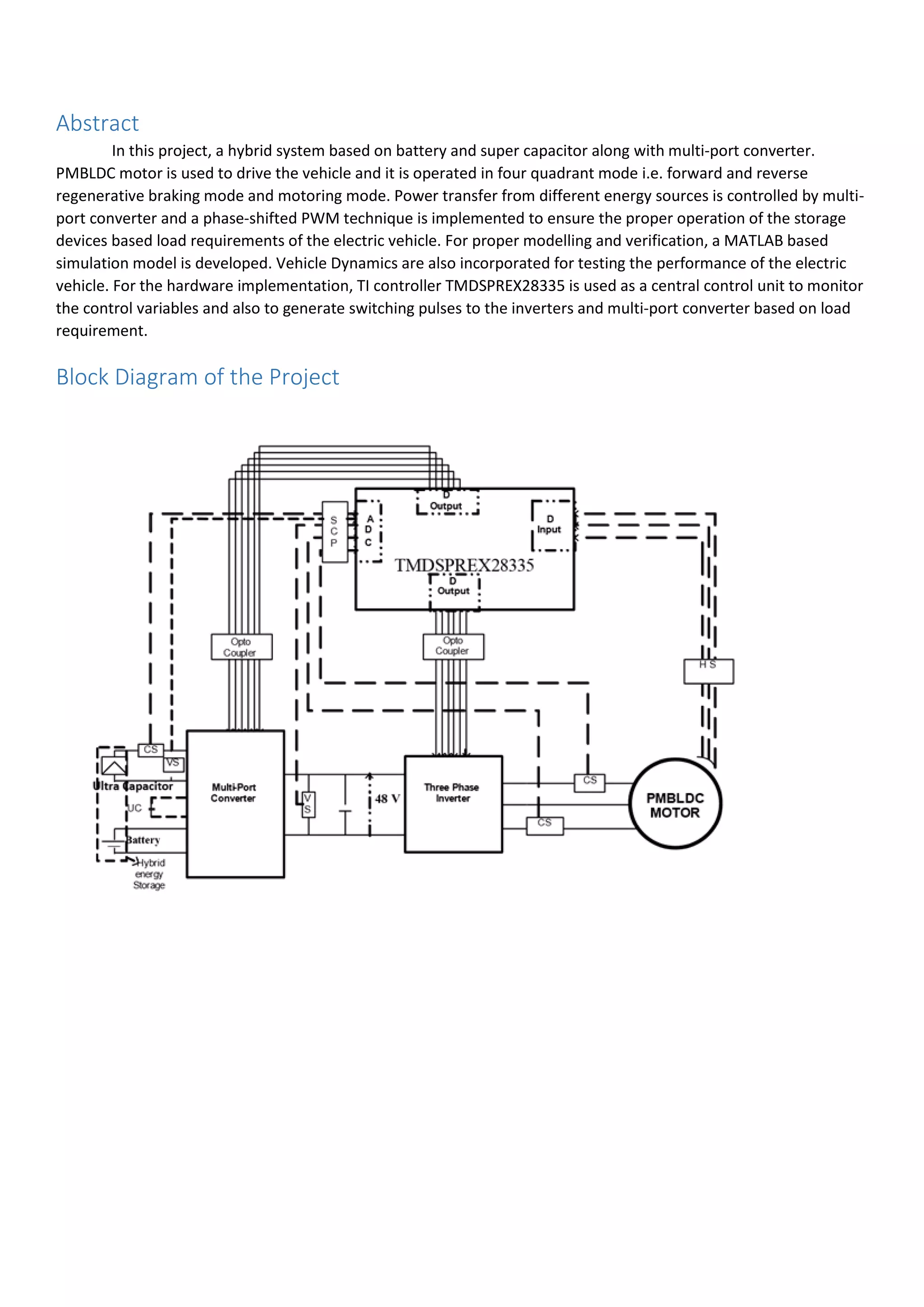
This document describes a project to design and control a hybrid energy storage system for a small plug-in electric vehicle. A battery and supercapacitor are used along with a multi-port converter. A permanent magnet brushless DC motor is used to drive the vehicle in four quadrants for forward, reverse, and regenerative braking modes. MATLAB simulation models are developed to model the power management system, motor drive, speed and current controllers, and vehicle dynamics. A DSP controller is used for hardware implementation, including driver circuits and interfacing with hall sensors to generate PWM signals for motor control. Future work includes integrating the power circuit with the motor, designing controllers for the bi-directional converter, implementing regenerative braking algorithms
![Contents
Abstract.............................................................................................................................................................................3
Block Diagram of the Project ............................................................................................................................................3
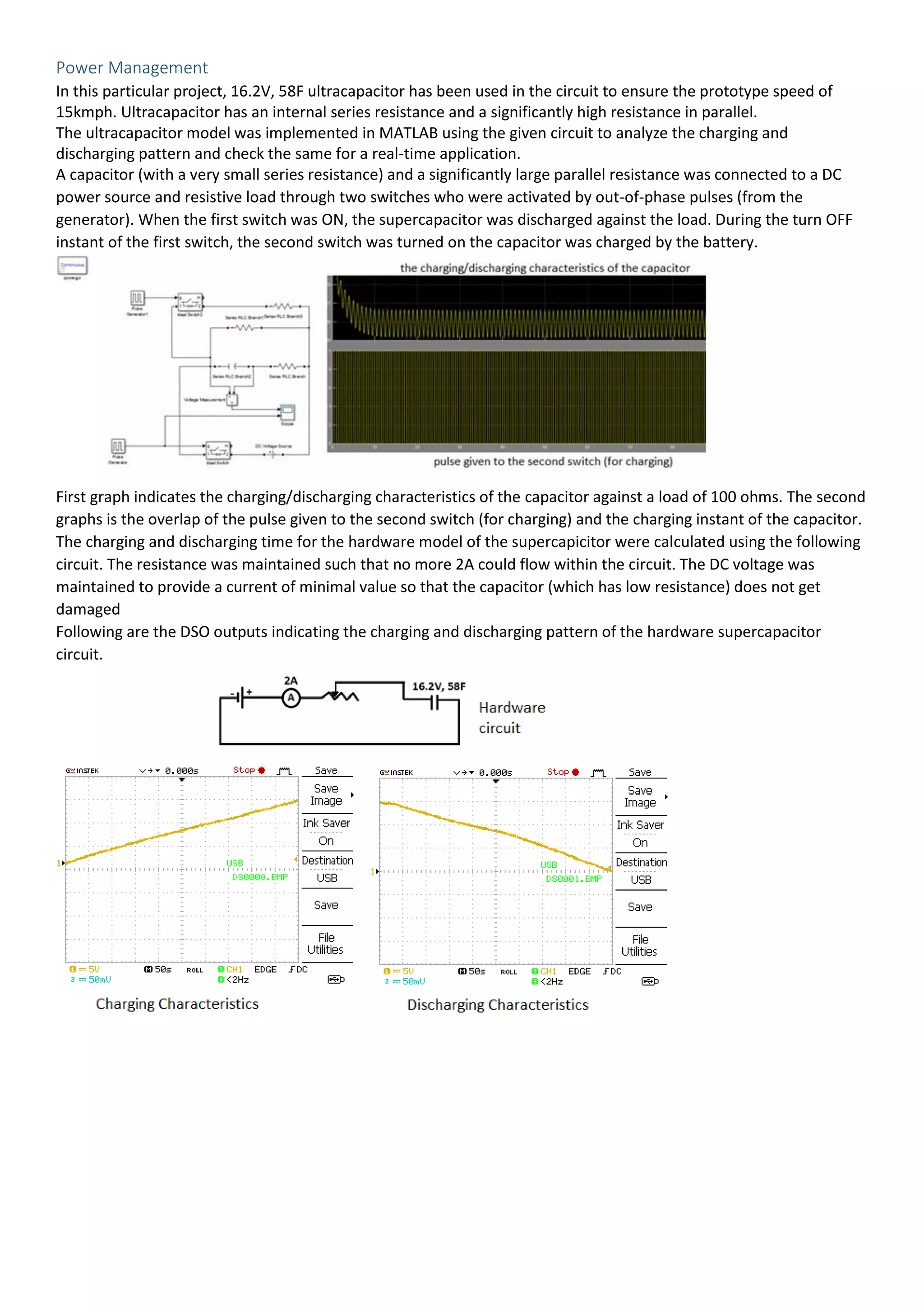
Power Management .........................................................................................................................................................4
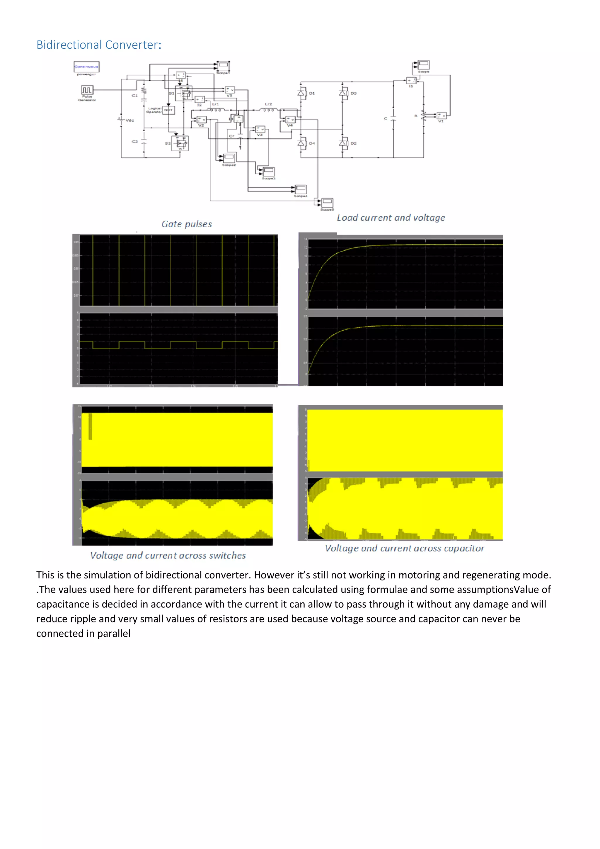
Bidirectional Converter:......................................................................................................................5
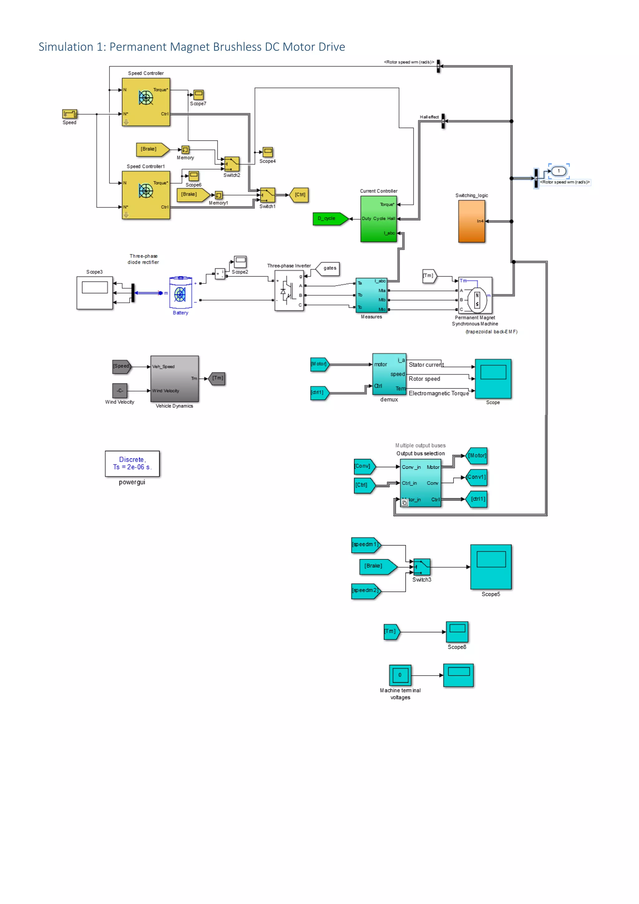
Simulation 1: Permanent Magnet Brushless DC Motor Drive ..........................................................................................6
Speed Controller ...............................................................................................................................................................7
Hysteresis Current Control........................................................................................................................................7
Modes of Operation – Switching Logic [2]........................................................................................................................8
Vehicle Dynamics [3].........................................................................................................................................................8
Model parameters for simulation.....................................................................................................................................8
Results...............................................................................................................................................................................9
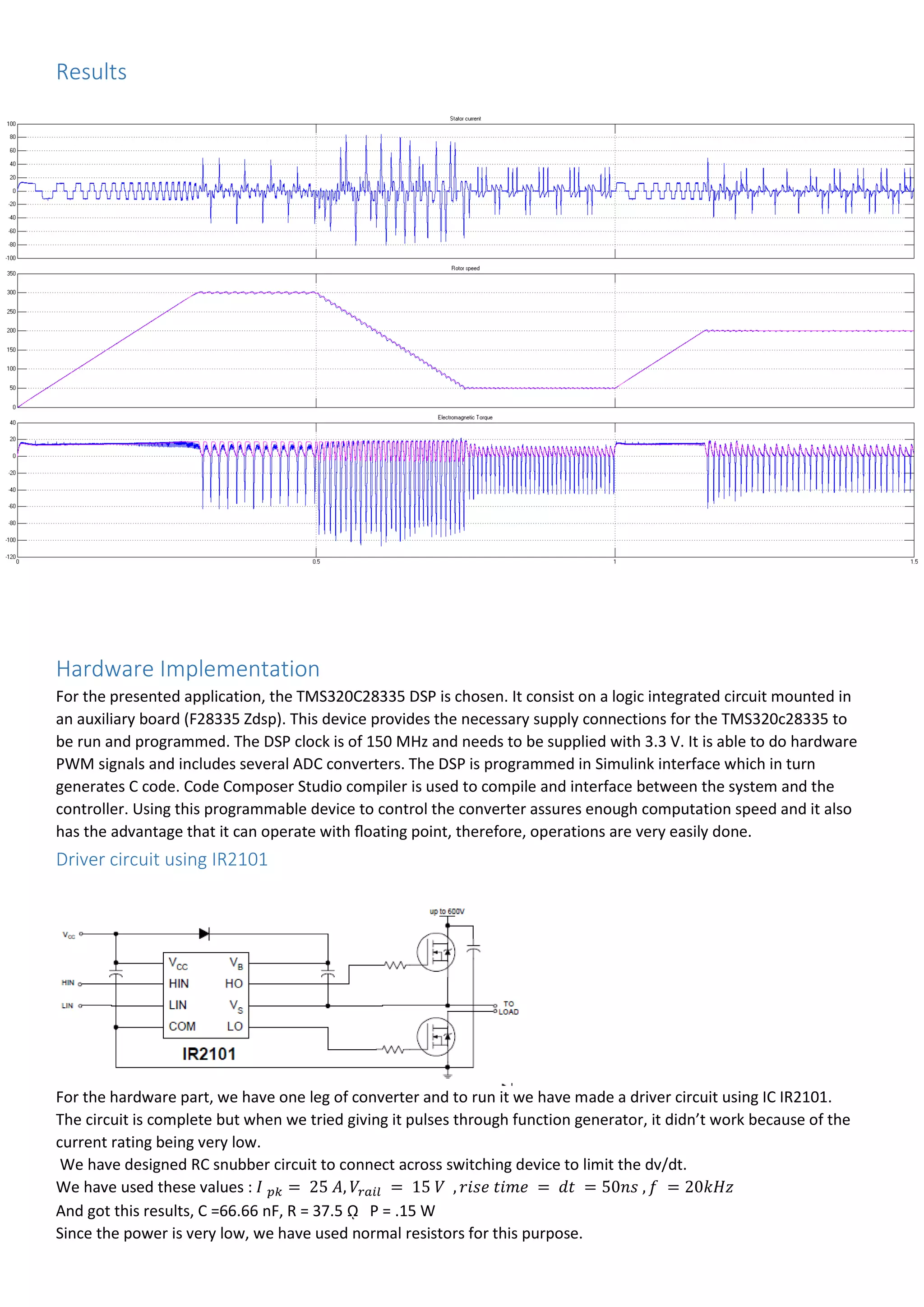
Hardware Implementation ...............................................................................................................................................9
Driver circuit using IR2101..................................................................................................................9
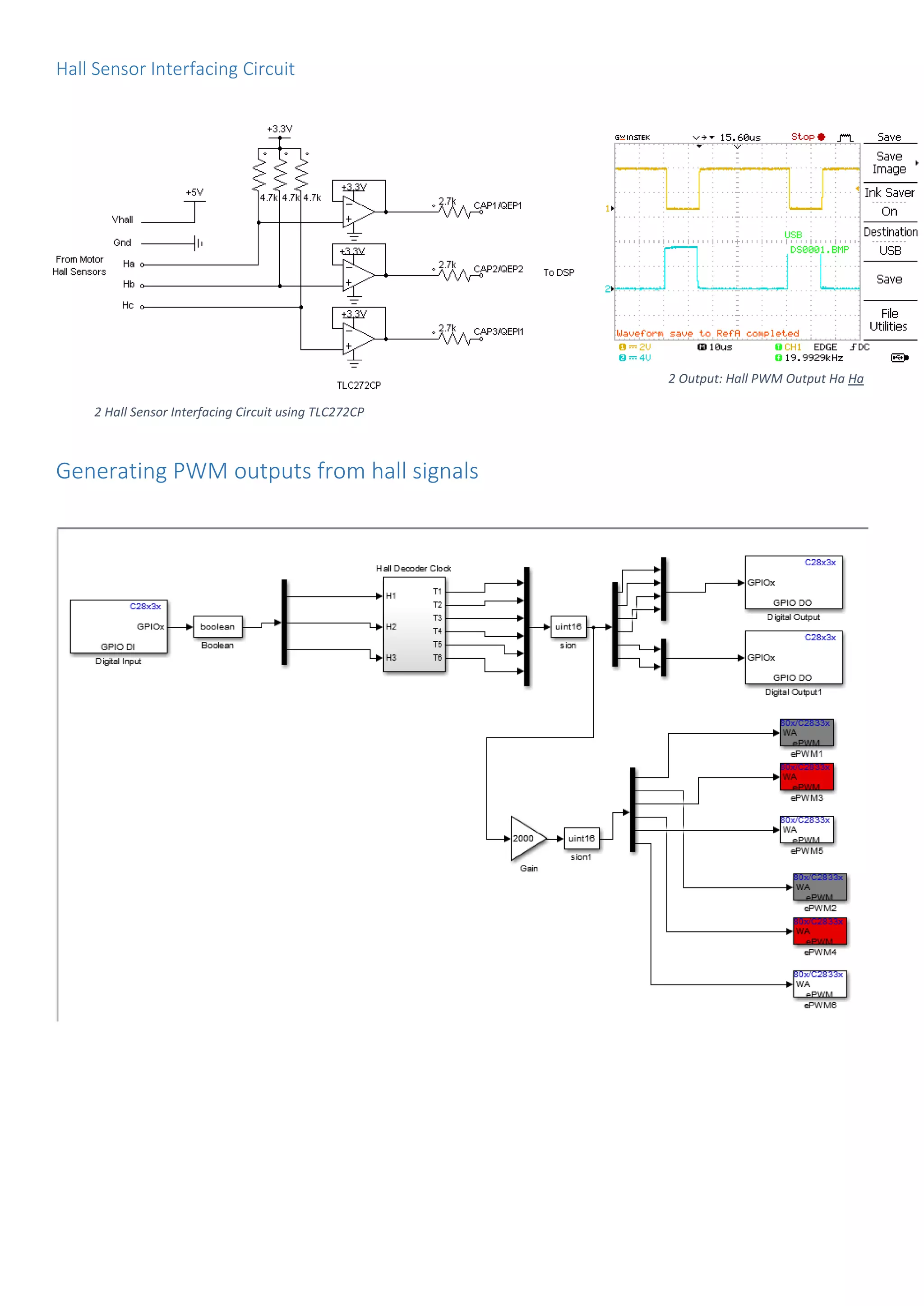
Hall Sensor Interfacing Circuit...........................................................................................................10
Generating PWM outputs from hall signals....................................................................................................................10
Simulation - Work Plan [4]..............................................................................................................................................11
Future Work....................................................................................................................................................................11](https://image.slidesharecdn.com/7e4bdaad-d97d-4d0a-b129-b9106d92a4aa-160213042223/75/Design-and-Control-of-HESS-based-PEV-2-2048.jpg)
![Speed Controller
Current Control [1]
Hysteresis Current Control](https://image.slidesharecdn.com/7e4bdaad-d97d-4d0a-b129-b9106d92a4aa-160213042223/75/Design-and-Control-of-HESS-based-PEV-7-2048.jpg)
![Modes of Operation – Switching Logic [2]
Vehicle Dynamics [3]
Model parameters for simulation
Battery:
Nominal_Voltage = 48;Rated_Capacity = 20;Initial_SOC = 80;
Control:
Speed_Cutoff_Freq = 285;Speed_Proportional_Gain = 4.9220; Speed_Integral_Gain =
446.7600;Speed_Torque_Saturation = [-17.3000, 17.3000];
Speed_Cutoff_Freq_Reg = 285;Speed_Proportional_Gain_Reg = 4.92; Speed_Integral_Gain_Reg =
446.76;Speed_Torque_Saturation_Reg = [-17.3000, 17.3000];
Hysteresis_Band = 0.0100; Hysteresis_Band_Motoring = 0.01;Hysteresis_Band_RegBrake = 0.01 ;
Inverter:
Rs = 66; Cs = 3.0000e-07;
Motor:
Rs = 0.1800; Ls = 5.4000e-04; Flux_Linkage = 0.0276;Inertia = 0.1324;Viscous_Damping = 0.0516;Poles = 23; Ke =
133;
Vehicle Dynamics:
Mass = 175; Tire_Radius = 0.2000;Aero_Drag_Coeff = 0.9200; Frontal_Area = 0.6000; Wind_Velocity = 0;
Air_Density = 1.2300; Gravitational_Constant = 9.8100; Gradient_Angle = 0; Rolling_Resistance = 0.0180;](https://image.slidesharecdn.com/7e4bdaad-d97d-4d0a-b129-b9106d92a4aa-160213042223/75/Design-and-Control-of-HESS-based-PEV-8-2048.jpg)
![Simulation - Work Plan [4]
All the parameters for this simulation are taken from standard research papers. Modelling of speed and
current controllers have been done using PI controller with some more features. Speed PI gain values have been
optimised using Ziegler - Nichols tuning method. Current controller although is a PI is just used for limiting range
between zero and one. In the current controller, hysteresis current control and pwm current control have been used
and performance is analysed and pwm current control has been selected for further research work. The forces which
the electric machine of the vehicle must overcome are the forces due to gravity, wind, rolling resistance, and inertial
effect and the EV propulsion system is modelled to meet the design requirements.
Various machine parameters such as rotor resistance, rotor inductance, inertia of the machine and voltage
constant have been measured. Controller has been successfully interfaced with Simulink and Code Composer Studio.
Hall sensor to controller interfacing circuits and gate driver circuits have been fabricated and tested. Decoder pulses
have been successfully generated and brushless dc motor is run in open loop using hall signals successfully.
Future Work
The power circuit will be integrated with the motor and the close control loop. The values of currents,
battery’s state of charge and voltage will be fed back by the control circuit to the converter and the acceleration and
retardation will be determined on the basis of the above parameters. The control of switches and designing of speed
and current controller for the bidirectional converter such that the converter will operate in four quadrant is to be
done. After which we have to give switching pulses to the one leg converter and we will have to integrate the load
with the Bi- directional converter.
Current PI will be tuned accordingly to reduce the ripple and optimise power using Ziegler - Nichols tuning
method. In Vehicle Dynamics, state flow model for a hybrid sources depending on speed and acceleration or brake
mechanism is proposed for a better implementation. Mechanical braking and simulation for a full urban cycle will be
included in the future simulation. Rigorous regenerative braking algorithms will be implemented for effective
braking.
Current sensors and voltage sensor should designed to meet the requirement of the controller and will be
fed into ADC of the controller. Various control algorithms should be implemented to incorporate current feedback
into the existing system. Speed measurement should be done by configure the eCAP pins in the controller to
incorporate speed feedback into the system.
Bibliography
[1] C. B. Roger, E. Mehrdad and M. J. Thomas, Four-Quadrant Brushless ECM Drive with Integrated Current
Regulation.
[2] Y. Ming-Ji, J. Hong-Lin, M. Bin-Yen, Kuo-Kai and Shyu, A Cost-Effective Method of Electric Brake With Energy
Regeneration for Electric Vehicles.
[3] M. Ehsani, K. M. Rahman and H. A. Toliyat, Propulsion System Design of Electric and Hybrid Vehicles.
[4] J. Faiz, M. Azizian and M. Aboulghasemian-Azami, Simulation and analysis of brushless DC motor drives using
hysteresis, ramp comparison and predictive current control techniques.
[5] P. PRGASAN and R. KNSHNAN, Modeling of Permanent Magnet Motor Drives.
[6] R.Krishnan, Permanent Magnet Synchronous and Brushless DC Motor Drives.](https://image.slidesharecdn.com/7e4bdaad-d97d-4d0a-b129-b9106d92a4aa-160213042223/75/Design-and-Control-of-HESS-based-PEV-11-2048.jpg)