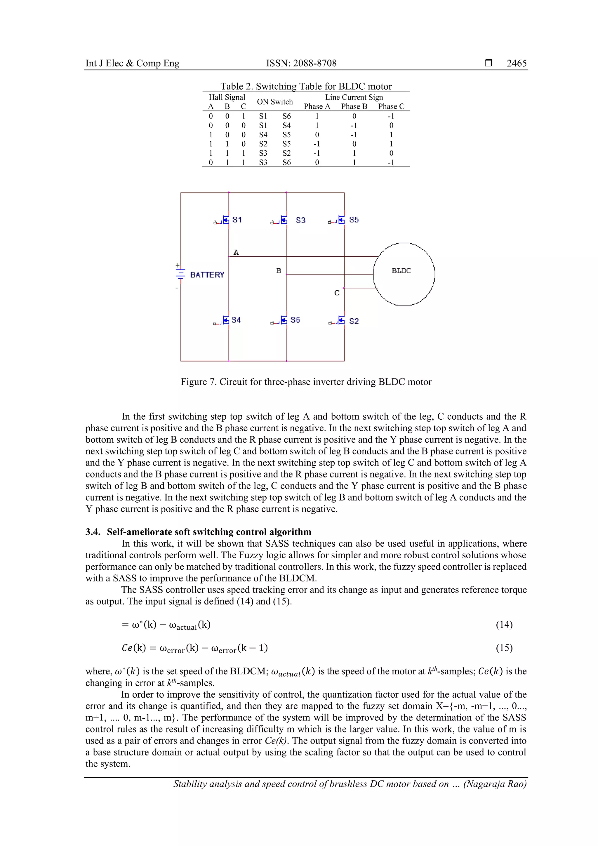
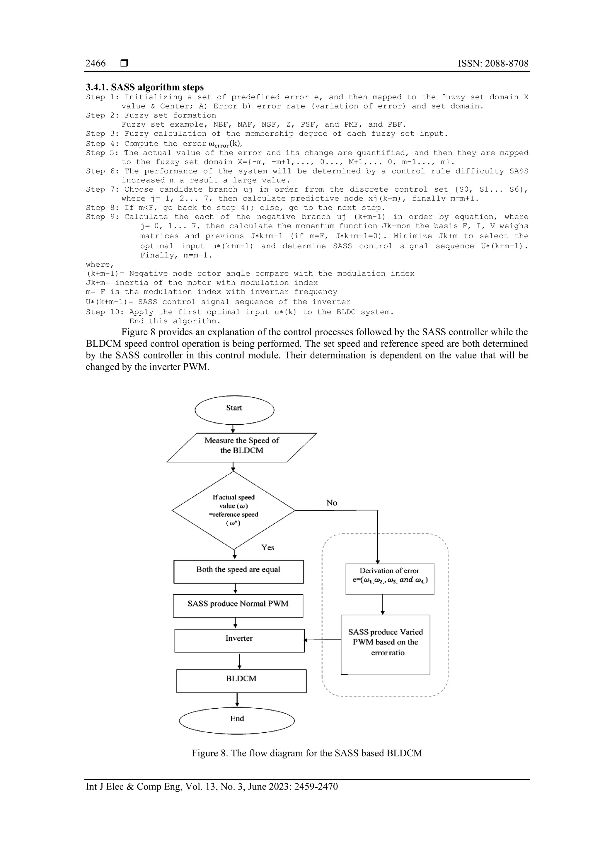
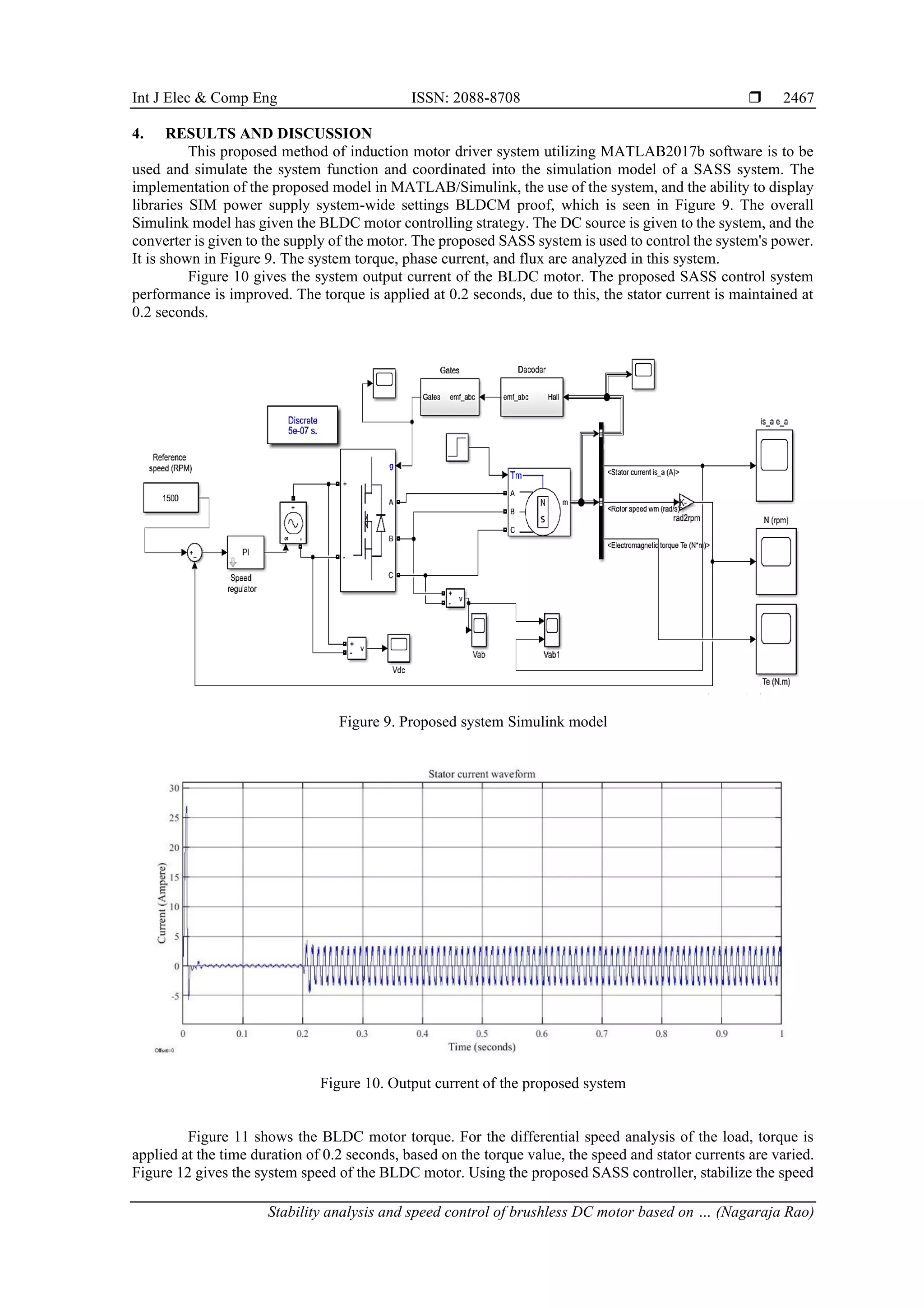
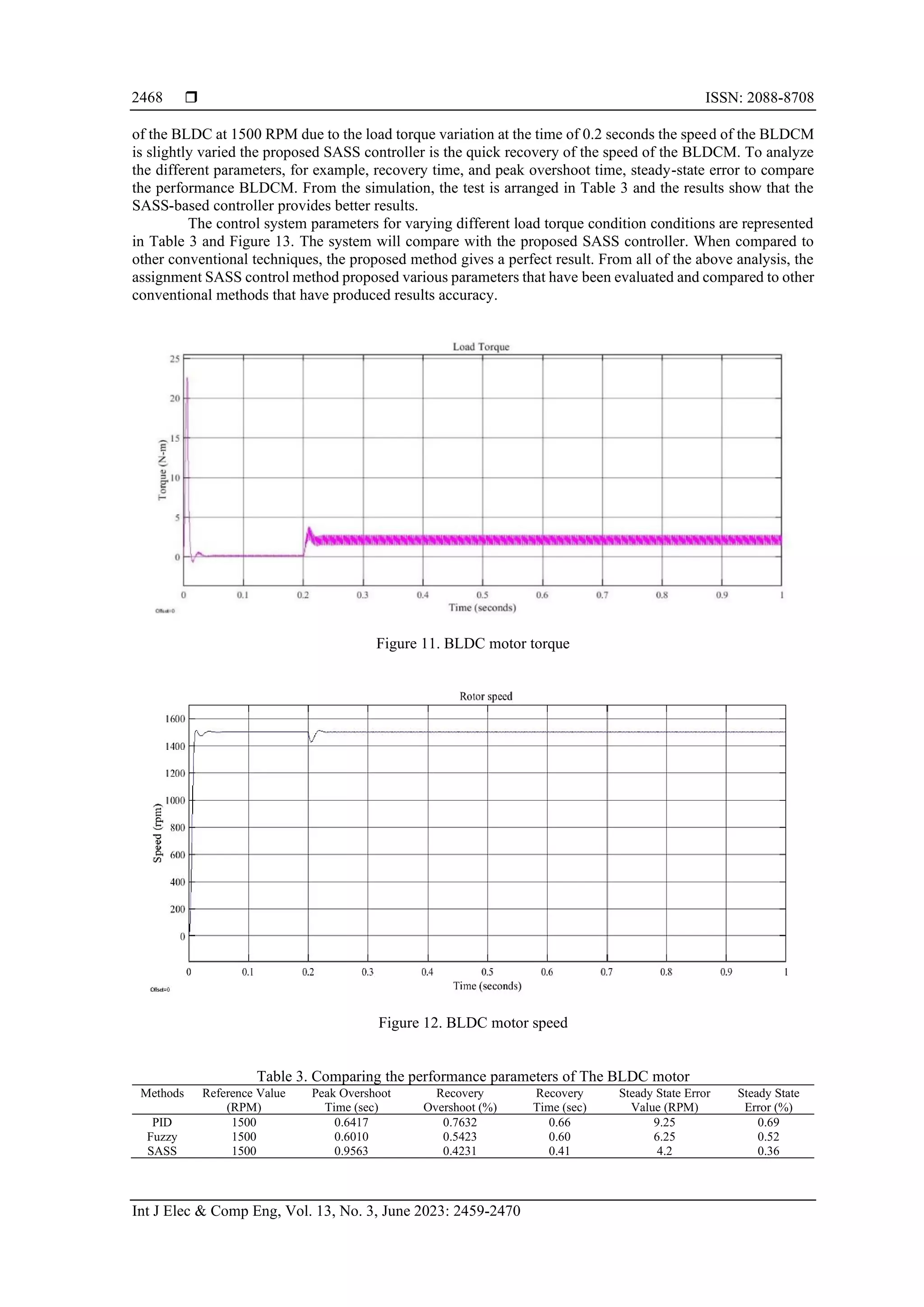
The document discusses the stability analysis and speed control of brushless DC motors (BLDCM) using a self-ameliorate soft switching (SASS) control method in electric vehicle applications. It highlights the importance of accurate speed control amidst load torque variations and presents a simulation model using MATLAB Simulink that demonstrates satisfactory performance with a maximum steady-state error of 4.2. The proposed system integrates fuzzy control techniques to optimize speed and torque management for improved efficiency and response in BLDCM operation.
![International Journal of Electrical and Computer Engineering (IJECE)
Vol. 13, No. 3, June 2023, pp. 2459~2470
ISSN: 2088-8708, DOI: 10.11591/ijece.v13i3.pp2459-2470 2459
Journal homepage: http://ijece.iaescore.com
Stability analysis and speed control of brushless DC motor
based on self-ameliorate soft switching control methods
Nagaraja Rao1
, Shantharama Rai Chelladka2
1
Department of Electronics and Communication Engineering, Faculty of Engineering, Shri Madhwa Vadiraja Institute of Technology
and Management, Udupi, India
2
Department of Electronics and Communication Engineering, Faculty of Engineering, AJ Institute of Engineering and Technology,
Mangalore, India
Article Info ABSTRACT
Article history:
Received Nov 12, 2021
Revised Oct 2, 2022
Accepted Dec 2, 2022
In recent years, electric vehicles are the large-scale spread of the
transportation field has led to the emergence of brushless direct current (DC)
motors (BLDCM), which are mostly utilized in electrical vehicle systems. The
speed control of a BLDCM is a subsystem, consisting of torque, flux
hysteresis comparators, and appropriate switching logic of an inverter. Due to
the sudden load torque variation and improper switching pulse, the speed of
the BLDCM is not maintained properly. In recent research, the BLDC current
control method gives a better way to control the speed of the motor. Also, the
rotor position information should be the need for feedback control of the
power electronic converters to varying the appropriate pulse width modulation
(PWM) of the inverter. The proposed optimization work controls the
switching device to manage the power supply BLDCM. In this proposed self-
ameliorate soft switching (SASS) system is a simple and effective way for
BLDC motor current control technology, a proposed control strategy is
intended to stabilize the speed of the BLDCM at different load torque
conditions. The proposed SASS system method is analyzing hall-based sensor
values continuously. The suggested model is simulated using the MATLAB
Simulink tool, and the results reveal that the maximum steady-state error value
achieved is 4.2, as well as a speedy recovery of the BLDCM's speed.
Keywords:
Brushless direct current motor
Driver circuit
Self-ameliorate soft switching
speed sensor
Torque-speed characteristics
This is an open access article under the CC BY-SA license.
Corresponding Author:
Nagaraja Rao
Department of Electronics and Communication Engineering, Faculty of Engineering, Shri Madhwa Vadiraja
Institute of Technology and Management
SMVITM, Bantakal, Udupi, India
Email: nagarajsmvitm1@gmail.com
1. INTRODUCTION
Recently, brushless direct current motors (BLDCM) have gained so much interest due to their simple
control and easy maintenance. In other motors, the brushless direct current (DC) motor about torque pulsation
shows better performance than the traditional positioning counterparts. This characteristic comes from the low
cogging torque of the brushless DC motor. The BLDCM has numerous features such as linear torque-speed
characteristics and easiest control arrangements, which do not necessitate complex hardware. The hall sensor-
based speed control of the BLDCM is shown in Figure 1.
In this work, Xia and Gao [1] presented that self-ameliorate soft switching (SASS) reduces the torque
ripple and the speed control of the BLDC motor. The typical method is pulse width modulation (PWM) control
plus a continuous control scheme. By controlling the current-based control structure the hysteresis controller
is utilized. Both of these systems have a high current control since the value of the controlled variable is forced](https://image.slidesharecdn.com/0926516emrn-230314071026-6189d2a2/75/Stability-analysis-and-speed-control-of-brushless-DC-motor-based-on-self-ameliorate-soft-switching-control-methods-1-2048.jpg)
![ ISSN: 2088-8708
Int J Elec & Comp Eng, Vol. 13, No. 3, June 2023: 2459-2470
2460
away from the surrounding reference value within certain limits. However, it is difficult to apply to the device
because this technology has a short hysteresis band ripple when the high switching frequency and large
hysteresis band are wide and uncontrollable. In contrast, the PWM current control with a lower current control,
but it has the advantage of a constant frequency switching device. Thus, the PWM method is suitable for low
hysteresis current control transistor switching losses and the power ratio. Moreover, the acoustic and
electromagnetic noise filter is relatively easy since the frequency is stable.
Figure 1. Functional block diagram for the BLDCM
As described above, the control voltage source inverter variable speed drive stability plays a key role,
cost minimization is becoming one of the proposed DC brushless motor control systems of most important
issues. In this system, a three-phase AC inverter drive is mainly applied and has certain advantages since, for
example, in a power transistor, conduction loss is reduced, reducing the number of the easier control algorithm,
to generate a switching signal. The appropriate switching signal will maintain the speed control of the BLDCM.
The SASS system provides a stability control operation of the BLDC motor. with this analysis the various
features like rise time (seconds), less settling time (seconds), and maximum overshoot (seconds) is obtained
with an effective ratio.
2. LITERATURE SURVEY
The growing demand for motorized applications such as electric vehicles and industrial automation
has led to increased interest in BLDCM due to their relatively small size and performance [2]. It proposes a
coordinated optimal shift control system for electric motor torque control, a two-speed gearbox introduced in
the process of slip clutch in electric vehicles. Among these, the torque of the motor and clutch thrust signals
are input to the optimized controller [3], [4]. A robust sliding mode controller (RSMC) was structured, and the
guided control law is separated into two sections: continuous and discontinuous. Delay problems with linear
quadratic regulators (LQRs) and networks have established goals to reduce reference state tracking errors and
reduce the control strength of the BLDCM [5]. Specifically, some safety regulation formulations for charging
electric vehicles (EVs) to ensure electrical safety and prevent dangerous accidents. Among them, the
requirements for need battery safety for electric vehicles are the two main driving factors. When connected to
renewable energy generation [4], the comprehensive system for assessing the electrical safety of large electrical
vehicle fast charging simplified (EVCSs). For mobile EVs, the only viable solution for electromagnetic energy
charging, inductive power transfer (IPT) cannot compare with other technologies, static offers the possibility
and includes dynamic charging [6].
The advantages of steering controllers for path tracking together with torque vectors [7] and path
tracking controllers are used in autonomous electric vehicles, either through integrated torque systems or
through separate implementations. A safe driving and control system is connected to automatically accelerating
or securing a vehicle safety constraint while optimizing deceleration [8]. It proposes an optimal method for any
type of charge depletion mode for versatile vitality utilization minimization methodology module of the electric
vehicle [9]. The adaptive sliding mode fault tolerant coordination (ASMFC) controller is used for speed control
of BLDCM. The sliding mode controller will analyze the speed at different time responses [10].
The dynamic remote force charging innovation of electric vehicles is a transmitter curl, which is put
under the ground. At the point when the electric vehicle and the getting should be overload the hysteresis
current controller should be regulate and stabilize the speed [11] to realize the wireless dynamic charging of
the vehicle, a modular multi-level converter (MMC) with basic embedded units, integrated balance function](https://image.slidesharecdn.com/0926516emrn-230314071026-6189d2a2/75/Stability-analysis-and-speed-control-of-brushless-DC-motor-based-on-self-ameliorate-soft-switching-control-methods-2-2048.jpg)
![Int J Elec & Comp Eng ISSN: 2088-8708
Stability analysis and speed control of brushless DC motor based on … (Nagaraja Rao)
2461
represents an effective alternative of the EV system [12]. The development of electric vehicles features the
charging network business market and forms, including the internet of things based communication system
[13] charging network policy. The hybrid energy storage system (HESS), along with high power density
ultra-capacitors, consists of high energy density battery packs. Motor drives for internal permanent magnet
(IPM) motors are usually designed depends on a fixed DC bus voltage [14].
To exploit this consecutive drive repetition to decrease machine corruption while guaranteeing that
the necessary shut circle execution [15]. It proposes another switched reluctance motor (SRM) with a wide
speed extend for EV applications [16]. Electric motors are generally reasonable for vehicle applications since
they can grow high beginning forces. This prompted the improvement of batteries for working EVs, In-wheel
operation of the wheel, and energy component vehicles [17]. Brushless DC motors are three-phase permanent
magnet motors and require a DC voltage as their power source [18].
Transportation is the principle segment that produces human wellbeing and air contamination, which
is poisonous to the reasons for an unnatural weather change. Air contamination can be limited by utilizing
sustainable power sources and propelled electric engines for inside ignition motor transportation [19]. Accurate
analysis of vehicle performance is required, including dynamic models of many components such as its electric
motor, its battery, and its motor controller [20]. Another regenerative braking system (RBS) has been proposed
for use in the EV and is driven by a brushless DC motor. During regenerative slowing down, BLDC is act as a
generator [21]. To meet the endless fuel demands of vehicles, research on hybrid vehicles with the wireless
battery charring system [22]. For high-efficiency energy recovery and safety series of hybrid electric vehicles,
the integrated braking system has a subsystem and advanced power consumption braking strategy are utilized
[23], [24]. In the open loop control of BLDC motor, speed is set to reference value, whereas in closed loop
control this is varied at any given time for the operation at desired speed. It is observed that, BLDC motor
running with fixed speed without having any significant ripples in torque. With the PI controller for closed
loop operation, performance of the motor has been modeled for the varying load [25], [26].
3. PROPOSED SYSTEM
The general structure of the proposed dynamic rule-based vector formed control fed BLDCM drive
model is showed up in Figure 2. It comprises of BLDCM, Inverter, position resolver, and controller. The speed
controller controlled BLDCM drives the feedback circuit in the external circuit, and the coordinated vector
current driver, which produces an effective result. When the phase current is detected at the time of
measurement, the current part of the torque and magnetic flux is gained through the coordinate transformation.
Then, the two currents are compared to a predetermined reference value, and through a single proportional
integral (PI) current controller, which determines the error handling nominal voltage at the motor terminals.
The actual speed of the motor is sensed and related with a reference value command. The rate error is processed
by the SASS speed controller, which determines the reference and the determined set point from the fuzzy rule.
The proposed SASS speed controller combines the benefits of fuzzy controllers.
Figure 2. Proposed block for speed control BLDCM
The load torque variation-based switching function is executed in a simulation model based on the
selected error value when the start time of the fuzzy controller. In running operation, the SASS controller to
provide better performance to vary the PWM signal according to the error ratio. Based on the error value
inverter will varying the speed of the BLDCM. During the movement, the transfer switch determines the SASS
controller to provide improved performance.](https://image.slidesharecdn.com/0926516emrn-230314071026-6189d2a2/75/Stability-analysis-and-speed-control-of-brushless-DC-motor-based-on-self-ameliorate-soft-switching-control-methods-3-2048.jpg)
![ ISSN: 2088-8708
Int J Elec & Comp Eng, Vol. 13, No. 3, June 2023: 2459-2470
2462
3.1. Modeling of BLDCM
Modeling of BLDCM can be developed similarly to three-phase synchronous motors. Due to the
permanent magnets installed on its rotor, some dynamic properties of the BLDCM are a different form of
synchronous motor. The flux linkage from the rotor depends on the magnet. Thus, the saturation magnetic flux
linkage is characteristic of such a motor. The typical structure of the voltage source inverter (VSI) fed BLDCM
is shown in Figure 3.
Figure 3. Three phase inverters based BLDCM
The armature modeling equation of BLDCM is expressed (1) to (3).
V1 = Ri1 + L1
di1
dt
+ E12 (1)
V2 = Ri2 + L2
di2
dt
+ E23 (2)
V3 = Ri3 + L3
di3
dt
+ E31 (3)
Or the compact matrix form is (4).
[
V1
V2
V3
]= [
R + pL 0 0
0 R + pL 0
0 0 R + pL
] [
i1
i2
i3
] + [
E12
E23
E31
] (4)
where the L1, L2, L3 is self-inductance and the R represents the armature resistance, also V1,V2, V3 = terminal
voltage, i1,i2, i3 = motor input current in ampere and E12,E23, E31 = motor back emf in volts. p in the matrix
represents
𝑑
𝑑𝑡
.
The modified back EMF must be expressed (5) to (7).
E12(t) = Ke ∅(θ) ω(t) (5)
E23(t) = Ke ∅ (θ −
2π
3
) ω(t) (6)
E31(t) = Ke ∅ (θ +
2π
3
) ω(t) (7)
where in, Ke is the back electromotive force constant, ω is the mechanical speed of the brushless DC motor. It
generates a torque that also affects the permanent magnet flux is a trapezoid.
Te =
(E1i1+E2i2+E3i3)
ω
(8)
The torque Te can be gained by the subsequent expression,
T1(t) = KT ∗ ∅(θ) ∗ i1(t) (9)](https://image.slidesharecdn.com/0926516emrn-230314071026-6189d2a2/75/Stability-analysis-and-speed-control-of-brushless-DC-motor-based-on-self-ameliorate-soft-switching-control-methods-4-2048.jpg)
![Int J Elec & Comp Eng ISSN: 2088-8708
Stability analysis and speed control of brushless DC motor based on … (Nagaraja Rao)
2463
T2(t) = KT ∗ ∅ (θ −
2π
3
) ∗ i2(t) (10)
T3(t) = KT ∅ ∗ (θ +
2π
3
) ∗ i1(t) (11)
TE(t) = (T1(t) + T2(t) + T3(t)) (12)
where, KT is the torque constant. The angular motion of the rotor can be expressed (13).
Te(t) = TL(t) = J
dw(t)
dt
+ B ∗ ω(t) (13)
where, TL (t) is load torque in N-m, J is rotor inertia in〖kgm〗^2, and B is damping constant
3.2. Self-ameliorate soft switching based closed-loop speed control operation
The Brushless DC motors can be controlled by controlling a three-phase inverter using SASS
switching pulses. Provides data about the required speed and torque values during an error condition in the
control unit. The BLDC motor drive control is used SASS as a switching controller which consists of three
main components, namely fuzzification, defuzzification, and dynamic rule decision logic interface. In Figure 4,
shows the input data is converted into suitable language variables. The input and output variable estimates are
numerical variables, and the resulting variable estimates are semantic factors, for example, negative big factor
(NBF), negative average factor (NAF), negative small factor (NSF), zero (Z), positive small factor (PSF),
positive average factor (PMF) and positive big factor (PBF).
Figure 4. SASS closed-loop block diagram
3.2.1. Fuzzification
Fuzzification is the first step in applying fuzzy inference systems. Most of the existing actual variables
(reference speed and torque) are scalable variables (reference speed). Those desired variables (input and output)
are converted into desired fuzzy variables, and then from the application to improve the SASS to process the
data inference to obtain the desired output. Finally, in most cases, those fuzzy output variables need to be
converted back to the desired, in order to achieve the desired control objectives.
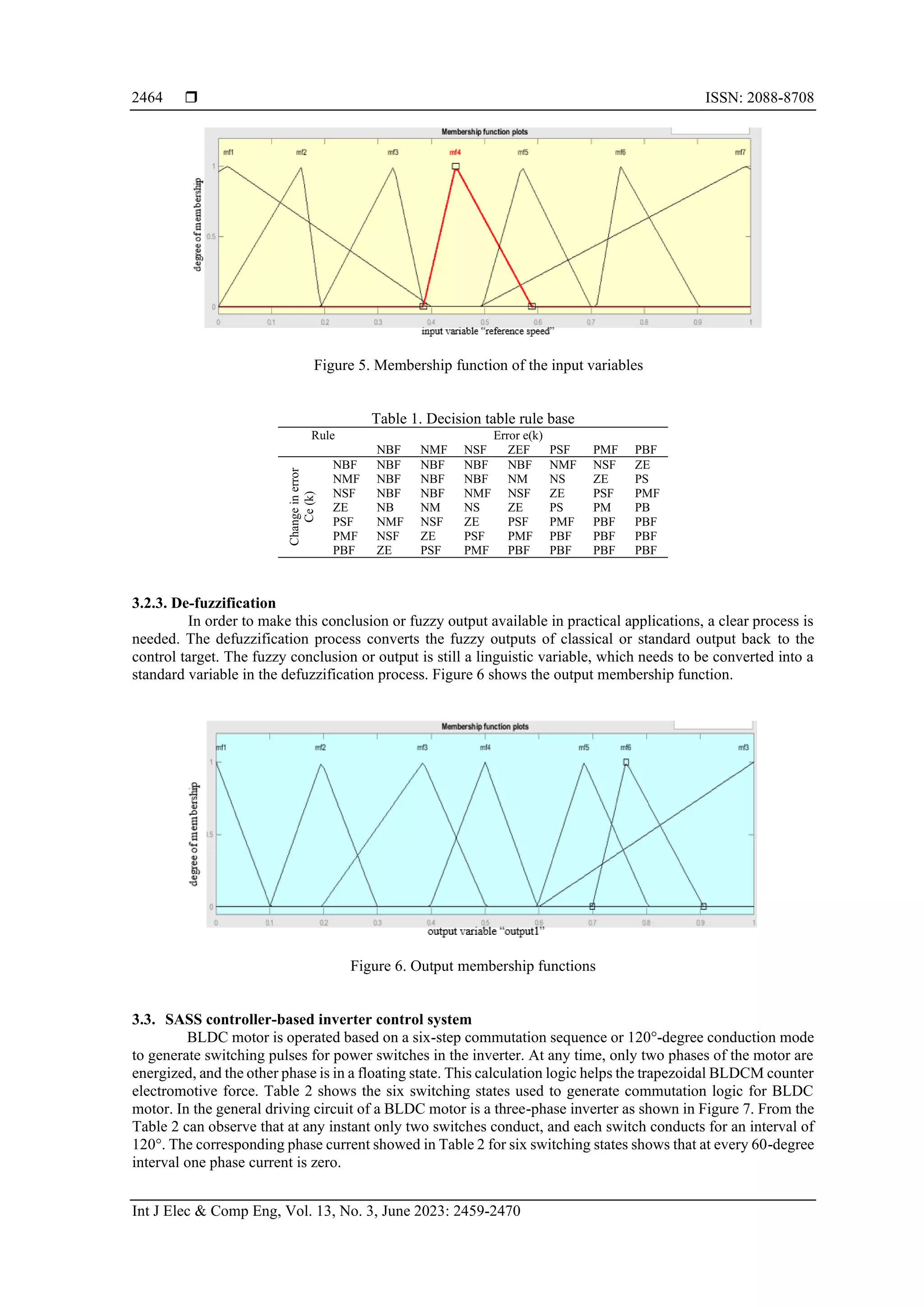
The triangular membership function is assigned to the input and output variables. As a function of the
error variable normalized interval [-1.1, 1.1]. The universe of discourse changes in the error function is
normalized in the interval [-0.04, 0.04]. Figure 5 shows the input membership functions.
3.2.2. Decision making logic
Input-output relational language choice rules are summarized in Table 1. The reasoning engine carries
out the instructions for Rule 49 (77), and it then processes the variables. MATLAB's fuzzy logic tools (FTL)
are used to do an interpretation of the rules based on the tables that were created for the rules' creation.](https://image.slidesharecdn.com/0926516emrn-230314071026-6189d2a2/75/Stability-analysis-and-speed-control-of-brushless-DC-motor-based-on-self-ameliorate-soft-switching-control-methods-5-2048.jpg)
![Int J Elec & Comp Eng ISSN: 2088-8708
Stability analysis and speed control of brushless DC motor based on … (Nagaraja Rao)
2469
Figure 13. Comparison analysis
5. CONCLUSION
This work introduces the modeling and simulation of the photovoltaics (PV) fed BLDC based water
pumping system mode with a controller, namely the SASS. The performance of the controllers has been
validated using MATLAB, and detailed analyses of all the parameters are presented. With this special model
results are obtained from simulation; it is clear that for the improvise operating condition for the BLDC speed
control; the steady-state value is 5.8% which is better than the existing controller. From the summary of results,
it can be presumed that error elimination and complete reduction of steady-state error are the unique features
of the proposed SASS controllers. The constant speed operation ensures the constant operation of the
automotive way. The advanced SASS control produces the maximum steady-state error value is 4.2.
REFERENCES
[1] C. Xia and G. Gao, “Brushless DC motors control based on smith predictor modified by fuzzy-PI controller,” in 2008 Fifth
International Conference on Fuzzy Systems and Knowledge Discovery, Oct. 2008, pp. 289–293, doi: 10.1109/FSKD.2008.65.
[2] N. A. Macahig, “A 6-wire 3-phase inverter topology for improved BLDC performance and harmonics,” in 2020 IEEE Applied
Power Electronics Conference and Exposition (APEC), Mar. 2020, pp. 741–744, doi: 10.1109/APEC39645.2020.9124358.
[3] P. Mishra, A. Banerjee, and M. Ghosh, “FPGA-based real-time implementation of quadral-duty digital-PWM-controlled permanent
magnet BLDC drive,” IEEE/ASME Transactions on Mechatronics, vol. 25, no. 3, pp. 1456–1467, Jun. 2020, doi:
10.1109/TMECH.2020.2977859.
[4] Q. Liu, L. Guo, B. Gao, K. Ye, H. Chen, and H. Guo, “Coordinate receding horizon control for the power-shift process of multispeed
electric vehicles,” IEEE Transactions on Vehicular Technology, vol. 69, no. 1, pp. 1055–1059, Jan. 2020, doi:
10.1109/TVT.2019.2949469.
[5] L. Zhang, Y. Wang, and Z. Wang, “Robust lateral motion control for in-wheel-motor-drive electric vehicles with network induced
delays,” IEEE Transactions on Vehicular Technology, vol. 68, no. 11, pp. 10585–10593, Nov. 2019, doi:
10.1109/TVT.2019.2942628.
[6] B. Wang, P. Dehghanian, S. Wang, and M. Mitolo, “Electrical safety considerations in large-scale electric vehicle charging stations,”
IEEE Transactions on Industry Applications, vol. 55, no. 6, pp. 6603–6612, Nov. 2019, doi: 10.1109/TIA.2019.2936474.
[7] D. Niculae, M. Iordache, M. Stanculescu, M. L. Bobaru, and S. Deleanu, “A review of electric vehicles charging technologies
stationary and dynamic,” in 2019 11th International Symposium on Advanced Topics in Electrical Engineering (ATEE), Mar. 2019,
pp. 1–4, doi: 10.1109/ATEE.2019.8724943.
[8] C. Chatzikomis, A. Sorniotti, P. Gruber, M. Zanchetta, D. Willans, and B. Balcombe, “Comparison of path tracking and torque-
vectoring controllers for autonomous electric vehicles,” IEEE Transactions on Intelligent Vehicles, vol. 3, no. 4, pp. 559–570, Dec.
2018, doi: 10.1109/TIV.2018.2874529.
[9] J. Han, A. Sciarretta, L. L. Ojeda, G. De Nunzio, and L. Thibault, “Safe- and eco-driving control for connected and automated
electric vehicles using analytical state-constrained optimal solution,” IEEE Transactions on Intelligent Vehicles, vol. 3, no. 2,
pp. 163–172, Jun. 2018, doi: 10.1109/TIV.2018.2804162.
[10] A. Rezaei, J. B. Burl, M. Rezaei, and B. Zhou, “Catch energy saving opportunity in charge-depletion mode, a real-time controller
for plug-In hybrid electric vehicles,” IEEE Transactions on Vehicular Technology, vol. 67, no. 11, pp. 11234–11237, Nov. 2018,
doi: 10.1109/TVT.2018.2866569.
[11] D. Zhang, G. Liu, H. Zhou, and W. Zhao, “Adaptive sliding mode fault-tolerant coordination control for four-wheel independently
driven electric vehicles,” IEEE Transactions on Industrial Electronics, vol. 65, no. 11, pp. 9090–9100, Nov. 2018, doi:
10.1109/TIE.2018.2798571.
[12] C. Liu et al., “Field circuit coupling analysis of dynamic wireless charging for electric vehicle,” in 2018 IEEE 2nd International
Electrical and Energy Conference (CIEEC), Nov. 2018, pp. 423–427, doi: 10.1109/CIEEC.2018.8745768.
[13] A. Del Pizzo, M. Coppola, and I. Spina, “Current waveforms distribution among electrochemical cells of modular multilevel
converters in battery electric vehicles,” in 2018 IEEE International Conference on Electrical Systems for Aircraft, Railway, Ship
Propulsion and Road Vehicles & International Transportation Electrification Conference (ESARS-ITEC), Nov. 2018, pp. 1–4, doi:
10.1109/ESARS-ITEC.2018.8607571.
[14] J. Zhang, H. Yan, N. Ding, J. Zhang, T. Li, and S. Su, “Electric vehicle charging network development characteristics and policy
suggestions,” in 2018 International Symposium on Computer, Consumer and Control (IS3C), Dec. 2018, pp. 469–472, doi:
10.1109/IS3C.2018.00124.
[15] M. O. Badawy, T. Husain, Y. Sozer, and J. A. De Abreu-Garcia, “Integrated control of an IPM motor drive and a novel hybrid
energy storage system for electric vehicles,” IEEE Transactions on Industry Applications, vol. 53, no. 6, pp. 5810–5819, Nov. 2017,
doi: 10.1109/TIA.2017.2741438.
0
5
10
15
Peak Time Recovery Overshoot (%) Recovery Time Steady State error value
(rpm)
Steady State Error (%)
performance
analysis(%)
Control method
Comparision Analysis PID Fuzzy SASS](https://image.slidesharecdn.com/0926516emrn-230314071026-6189d2a2/75/Stability-analysis-and-speed-control-of-brushless-DC-motor-based-on-self-ameliorate-soft-switching-control-methods-11-2048.jpg)
![ ISSN: 2088-8708
Int J Elec & Comp Eng, Vol. 13, No. 3, June 2023: 2459-2470
2470
[16] L. Samaranayake and S. Longo, “Degradation control for electric vehicle machines using nonlinear model predictive control,” IEEE
Transactions on Control Systems Technology, vol. 26, no. 1, pp. 89–101, Jan. 2018, doi: 10.1109/TCST.2016.2646322.
[17] J. Zhu, K. W. E. Cheng, X. Xue, and Y. Zou, “Design of a new enhanced torque in-wheel switched reluctance motor with divided
teeth for electric vehicles,” IEEE Transactions on Magnetics, vol. 53, no. 11, pp. 1–4, Nov. 2017, doi:
10.1109/TMAG.2017.2703849.
[18] V. P. Dhote, M. M. Lokhande, A. Agrawal, and B. H. Kumar, “Mechanical coupling of two induction motor drives for the
applications of an electric-drive vehicle system,” in 2017 National Power Electronics Conference (NPEC), Dec. 2017,
pp. 330–333, doi: 10.1109/NPEC.2017.8310480.
[19] A. Jaya, E. Purwanto, M. B. Fauziah, F. D. Murdianto, G. Prabowo, and M. R. Rusli, “Design of PID-fuzzy for speed control of
brushless DC motor in dynamic electric vehicle to improve steady-state performance,” in 2017 International Electronics Symposium
on Engineering Technology and Applications (IES-ETA), Sep. 2017, pp. 179–184, doi: 10.1109/ELECSYM.2017.8240399.
[20] J. J. Joseph, T. A. A. Victoire, M. C. Joseph, and F. T. Josh, “Axial flux permanent magnet motor-driven battery powered electric
vehicle with zeta converter,” in 2017 International Conference on Innovations in Electrical, Electronics, Instrumentation and Media
Technology (ICEEIMT), Feb. 2017, pp. 353–358, doi: 10.1109/ICIEEIMT.2017.8116865.
[21] A. Saleki, S. Rezazade, and M. Changizian, “Analysis and simulation of hybrid electric vehicles for sedan vehicle,” in 2017 Iranian
Conference on Electrical Engineering (ICEE), May 2017, pp. 1412–1416, doi: 10.1109/IranianCEE.2017.7985263.
[22] F. Naseri, E. Farjah, and T. Ghanbari, “An efficient regenerative braking system based on battery/supercapacitor for electric, hybrid
and plug-in hybrid electric vehicles with BLDC motor,” IEEE Transactions on Vehicular Technology, vol. 66, no. 5,
pp. 3724–3738, 2016, doi: 10.1109/TVT.2016.2611655.
[23] M. S. Alam Chowdhury, K. A. Al Mamun, and A. M. Rahman, “Modelling and simulation of power system of battery, solar and
fuel cell powered hybrid electric vehicle,” in 2016 3rd International Conference on Electrical Engineering and Information
Communication Technology (ICEEICT), Sep. 2016, pp. 1–6, doi: 10.1109/CEEICT.2016.7873126.
[24] X. Sun, C. Shao, G. Wang, L. Yang, X. Li, and Y. Yue, “Research on electrical brake of a series-parallel hybrid electric vehicle,”
in 2016 World Congress on Sustainable Technologies (WCST), Dec. 2016, pp. 70–75, doi: 10.1109/WCST.2016.7886594.
[25] P. Sarala, S. F. Kodad, and B. Sarvesh, “Analysis of closed loop current controlled BLDC motor drive,” in 2016 International
Conference on Electrical, Electronics, and Optimization Techniques (ICEEOT), Mar. 2016, pp. 1464–1468, doi:
10.1109/ICEEOT.2016.7754925.
[26] A. Varshney and B. Dwivedi, “Performance analysis of a BLDC drive under varying load,” in 2016 IEEE 1st International
Conference on Power Electronics, Intelligent Control and Energy Systems (ICPEICES), Jul. 2016, pp. 1–4, doi:
10.1109/ICPEICES.2016.7853626.
BIOGRAPHIES OF AUTHORS
Nagaraja Rao received a B.E. degree in electrical and electronics engineering and
M.Tech. in microelectronics and control systems from NMAMIT, Nitte in 2003 and 2005,
respectively. He is working as an associate professor in the Department of ECE at SMVITM,
Bantakal. Prior to joining SMVITM, he was working as an assistant professor in EEE
Department at The Oxford College of Engineering Bangalore. He is having a total of 16 years
of teaching experience. Presently, he is pursuing his Ph.D. in the area of control engineering
under the guidance of Dr. Shantharama Rai, Principal, AJIET, Mangalore. His areas of interest
are control engineering, modern control engineering, circuit theory, and digital signal
processing. He is a life member of ISTE and ISTD. He has published/presented around 10 papers
in international/national journals/conferences in the field of engineering. He can be contacted at
nagarajsmvitm1@gmail.com.
Shantharama Rai Chelladka completed his Bachelor of Engineering (B.E.) from
Mangalore University, M.Tech. from N.I.T.K. Surathkal, and Ph.D. from V.T.U Belgaum with
a specialization in power electronics and control systems. He is also a member of Indian Society
for Technical Education, New Delhi, and Indian Society for Lighting Engineers, New Delhi. He
has served in different institutions/organizations like K.V.G. College of Engineering, Sullia,
N.M.A.M. Institute of Technology, Nitte, St. Joseph Engineering College Vamanjoor, and
Canara Engineering college Mangalore in various capacities for more than 18 years. He has
published/presented more than 40 papers in international/national journals/conferences in the
field of engineering He has guided more than 50 UG projects, and more than 15 PG projects.
Presently, he is guiding 7 Ph.D. students. The project guided by him titled Generation of Electric
Power from Waste Products Using Specially Designed Spark Ignition Engine is awarded as the
quality of very high order and obtained the certificate of commendation from Karnataka State
Council for Science and Technology, Indian Institute of Science Bangalore. He also obtained
more than 35 lacs grant for his research work from VTU and AICTE New Delhi. Dr.
Shantharama Rai C. has participated in and presented a research paper in the state of Kuwait.
He was the coordinator for the Mangalore Region to assess the Quality of Electrical Distribution
Governance and Performance in Karnataka (MESCOM Region) appointed by K.S.C.S.T
Bangalore for the year 2007-2008. He is also an executive member of different organizations in
Mangalore and serves to the public through many organizations Dr. Rai was also a member of
Ph.D. candidate selection, a member of the examination committee (BOE), and the local
inspection committee of Visvesvaraya Technological University Belgaum Karnataka. He can
be contacted at principal@ajiet.edu.in.](https://image.slidesharecdn.com/0926516emrn-230314071026-6189d2a2/75/Stability-analysis-and-speed-control-of-brushless-DC-motor-based-on-self-ameliorate-soft-switching-control-methods-12-2048.jpg)


![[000007]](https://cdn.slidesharecdn.com/ss_thumbnails/000007-211028000533-thumbnail.jpg?width=640&height=640&fit=bounds)


