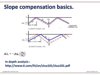
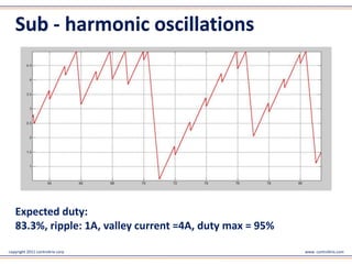
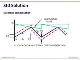
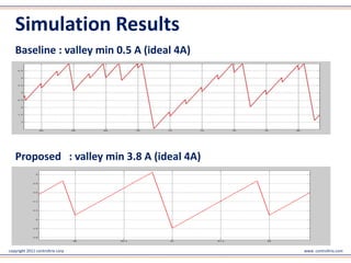
Digitally controlled power supply

                              Perspective on Slope Compensation


                                      www.controltrix.com


copyright 2011 controltrix corp                                   www. controltrix.com
Slope compensation basics
     Switched mode power converter operating under:
     • Peak current mode control
     • Fixed PWM frequency
     • Continuous conduction mode
     • Duty > 50%

     Results in Sub-harmonic oscillations and instability !!!!


copyright 2011 controltrix corp                                  www. controltrix.com
Slope compensation basics.


     In depth analysis :
     http://www.ti.com/lit/an/slua101/slua101.pdf
copyright 2011 controltrix corp                     www. controltrix.com
Sub - harmonic oscillations


   Expected duty:
   83.3%, ripple: 1A, valley current =4A, duty max = 95%

copyright 2011 controltrix corp                            www. controltrix.com
Std Solution
   Use slope compensation


copyright 2011 controltrix corp   www. controltrix.com
Slope choices
                       Merits                  De-Merits
    m = m2 / 2 • Behaves like average • Convergence issues at
                 current mode control   higher duty ratios (~ 0.9)

   m = 2 * m2 • Guaranteed                                 • Voltage mode control
                convergence                                  equivalent
                                                           • Poor dynamic line
                                                             regulation
        m = m2                    • Fastest single cycle   • Not true current mode
                                    convergence              control.
                                                           • Poor dynamic line
                                                             regulation
copyright 2011 controltrix corp                                                www. controltrix.com
Digital Power adopting analog legacy
   •      Analog circuit with switch or extra DSP PWM
   •      Fixed slope value (m)
   •      Wide range input and output fixed
   •      slope m is suboptimal
   •      Finding m1, m2 hard with inductance changes with load


copyright 2011 controltrix corp                                   www. controltrix.com
Other Methods
   •      Find intersection point of slope m1 and m in Software
   •      Defeats peak current mode control
   •      Sub harmonic oscillations still present
   •      Needs noise free ADC measurement of valley current (hard)


copyright 2011 controltrix corp                                  www. controltrix.com
Proposed method Features
   • Only Software / firmware no extra hardware
   • Few extra mips (<1us extra execution per cycle @40 mips /
     40MHz proc)
   • Wide input / output voltage acceptable
   • Maintains nearly stable effective duty


copyright 2011 controltrix corp                              www. controltrix.com
Proposed method Features.
   • Supports all duty ratios
   • Reduces instability (current ripple deviation) by factor of
     10X or more
   • Higher duties more improvement factor
   • True peak current mode control dynamics
   • Patent pending


copyright 2011 controltrix corp                                    www. controltrix.com
Tradeoffs
   • May need extra PWM channel.
     (Depends on DSC peripheral availability)
   • Bounded overshoot above current limit.
   • Periodic sub harmonics still present (smaller amplitude)


copyright 2011 controltrix corp                                 www. controltrix.com
Test conditions
   •       4A valley expected at steady state.
   •       5A peak (current reference).
   •       83.3% duty.
   •       95% max duty.
   •       1 unit period.
   •       Figure of merit : minimum valley current.


copyright 2011 controltrix corp                        www. controltrix.com
Simulation Results
   Baseline : valley min 0.5 A (ideal 4A)


   Proposed : valley min 3.8 A (ideal 4A)


copyright 2011 controltrix corp             www. controltrix.com
Thank You
                                  consulting@controltrix.com


copyright 2011 controltrix corp                                www. controltrix.com

Digitally controlled power supply - a perspective on slope compensation

  • 1.
    Digitally controlled powersupply Perspective on Slope Compensation www.controltrix.com copyright 2011 controltrix corp www. controltrix.com
  • 2.
    Slope compensation basics Switched mode power converter operating under: • Peak current mode control • Fixed PWM frequency • Continuous conduction mode • Duty > 50% Results in Sub-harmonic oscillations and instability !!!! copyright 2011 controltrix corp www. controltrix.com
  • 3.
    Slope compensation basics. In depth analysis : http://www.ti.com/lit/an/slua101/slua101.pdf copyright 2011 controltrix corp www. controltrix.com
  • 4.
    Sub - harmonicoscillations Expected duty: 83.3%, ripple: 1A, valley current =4A, duty max = 95% copyright 2011 controltrix corp www. controltrix.com
  • 5.
    Std Solution Use slope compensation copyright 2011 controltrix corp www. controltrix.com
  • 6.
    Slope choices Merits De-Merits m = m2 / 2 • Behaves like average • Convergence issues at current mode control higher duty ratios (~ 0.9) m = 2 * m2 • Guaranteed • Voltage mode control convergence equivalent • Poor dynamic line regulation m = m2 • Fastest single cycle • Not true current mode convergence control. • Poor dynamic line regulation copyright 2011 controltrix corp www. controltrix.com
  • 7.
    Digital Power adoptinganalog legacy • Analog circuit with switch or extra DSP PWM • Fixed slope value (m) • Wide range input and output fixed • slope m is suboptimal • Finding m1, m2 hard with inductance changes with load copyright 2011 controltrix corp www. controltrix.com
  • 8.
    Other Methods • Find intersection point of slope m1 and m in Software • Defeats peak current mode control • Sub harmonic oscillations still present • Needs noise free ADC measurement of valley current (hard) copyright 2011 controltrix corp www. controltrix.com
  • 9.
    Proposed method Features • Only Software / firmware no extra hardware • Few extra mips (<1us extra execution per cycle @40 mips / 40MHz proc) • Wide input / output voltage acceptable • Maintains nearly stable effective duty copyright 2011 controltrix corp www. controltrix.com
  • 10.
    Proposed method Features. • Supports all duty ratios • Reduces instability (current ripple deviation) by factor of 10X or more • Higher duties more improvement factor • True peak current mode control dynamics • Patent pending copyright 2011 controltrix corp www. controltrix.com
  • 11.
    Tradeoffs • May need extra PWM channel. (Depends on DSC peripheral availability) • Bounded overshoot above current limit. • Periodic sub harmonics still present (smaller amplitude) copyright 2011 controltrix corp www. controltrix.com
  • 12.
    Test conditions • 4A valley expected at steady state. • 5A peak (current reference). • 83.3% duty. • 95% max duty. • 1 unit period. • Figure of merit : minimum valley current. copyright 2011 controltrix corp www. controltrix.com
  • 13.
    Simulation Results Baseline : valley min 0.5 A (ideal 4A) Proposed : valley min 3.8 A (ideal 4A) copyright 2011 controltrix corp www. controltrix.com
  • 14.
    Thank You consulting@controltrix.com copyright 2011 controltrix corp www. controltrix.com