The document provides an overview of Data Flow Diagrams (DFDs), highlighting their purpose in modeling the flow of data within information systems during both analysis and design phases. It details the four symbols used in DFDs—external entity, process, data store, and data flow—and discusses the rules for creating diagrams at various levels (0 to 2). Furthermore, it includes common rules for DFDs, potential errors, and an example involving a bus garage repair system to illustrate the concepts.
2
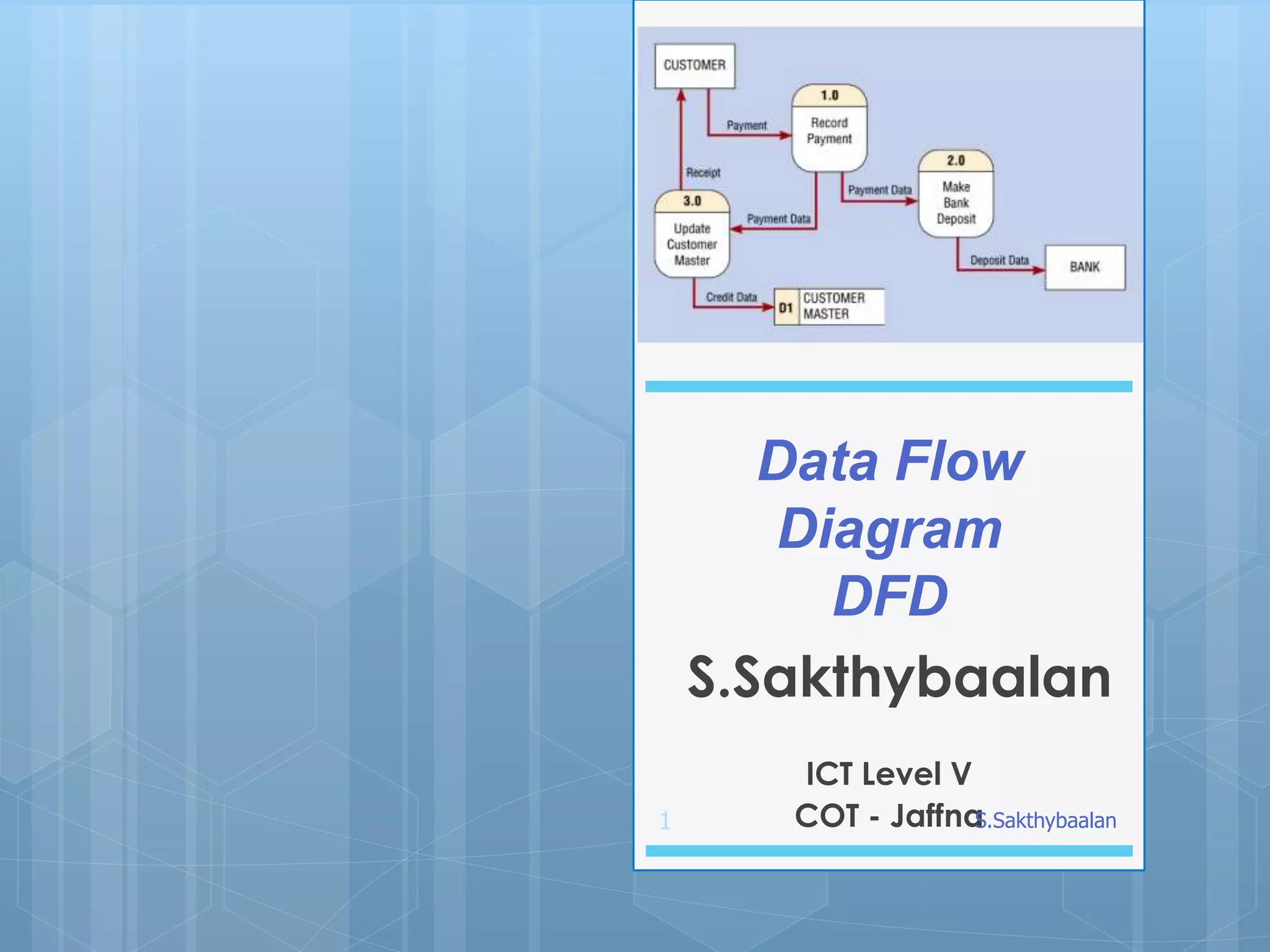
A Data FlowDiagram (DFD) is a
graphical representation of the "flow"
of data through an information system,
modeling its process aspects.
Data Flow Diagram (DFD)
S.Sakthybaalan
3.
3
Examples of LCs
DFDsare attractive technique
because they provide what users do
rather than what computers do.
Data Flow Diagrams can be used in
both Analysis and Design phase of
the SDLC.
S.Sakthybaalan
4.
4
DFDs only involvefour symbols.
•Entity
•Process
•Data store
•Data flow
S.Sakthybaalan
5.
5
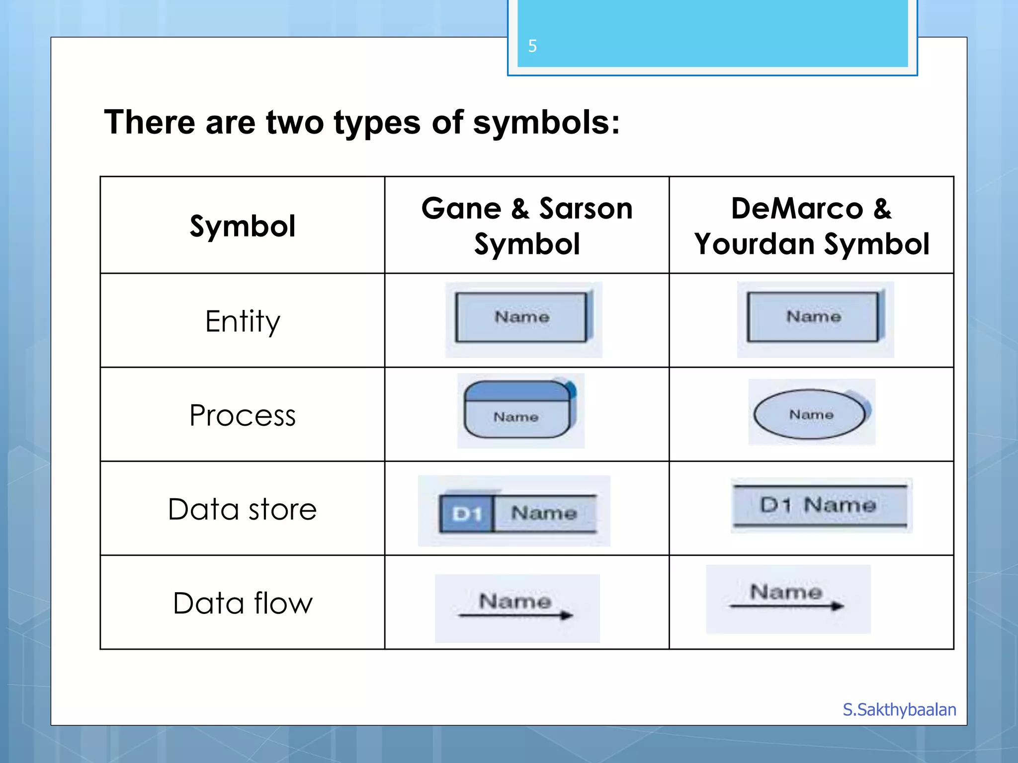
There are twotypes of symbols:
Symbol
Gane & Sarson
Symbol
DeMarco &
Yourdan Symbol
Entity
Process
Data store
Data flow
S.Sakthybaalan
6.
6
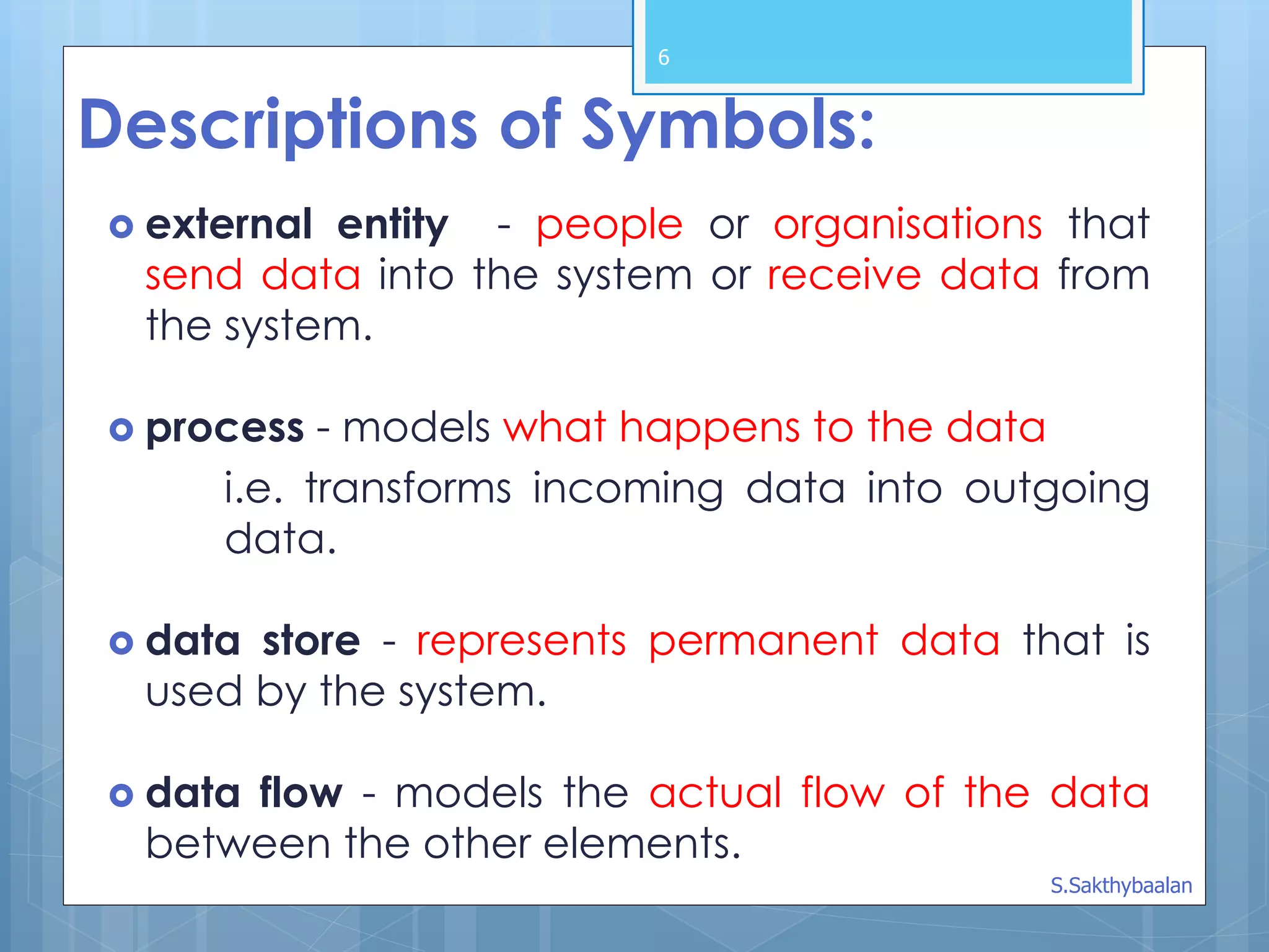
Descriptions of Symbols:
external entity - people or organisations that
send data into the system or receive data from
the system.
process - models what happens to the data
i.e. transforms incoming data into outgoing
data.
data store - represents permanent data that is
used by the system.
data flow - models the actual flow of the data
between the other elements.
S.Sakthybaalan
7.
7
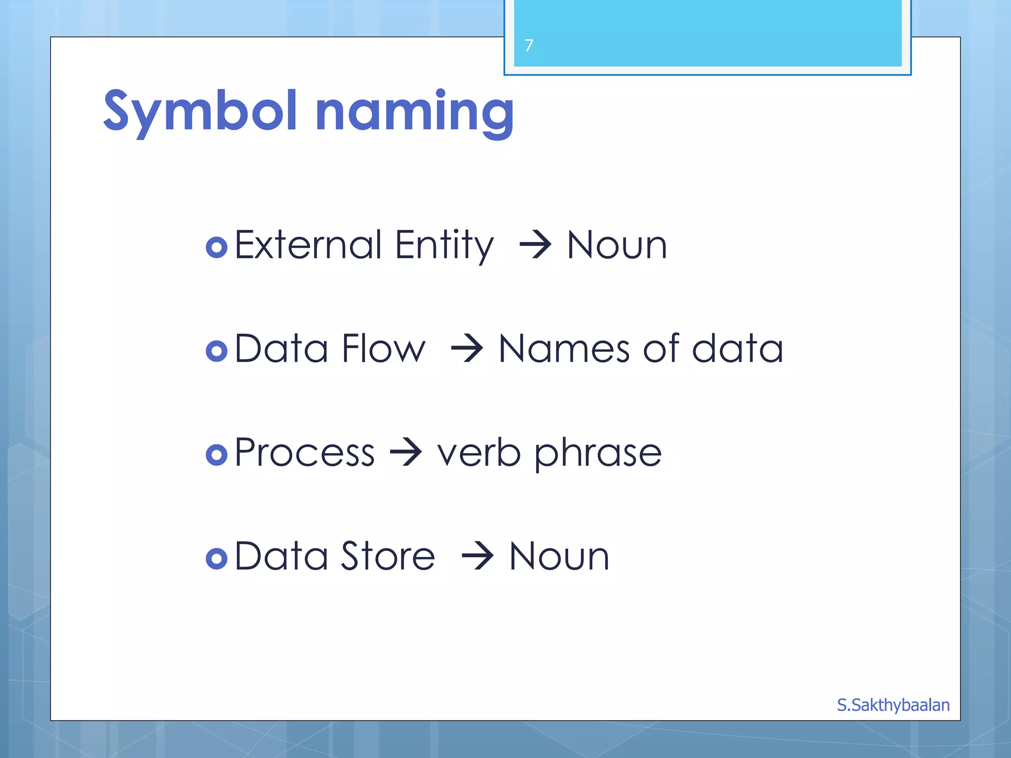
External Entity Noun
Data Flow Names of data
Process verb phrase
Data Store Noun
Symbol naming
S.Sakthybaalan
8.
8
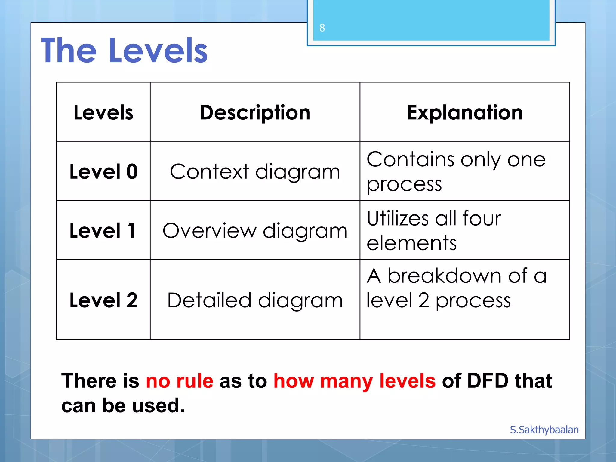
The Levels
Levels DescriptionExplanation
Level 0 Context diagram
Contains only one
process
Level 1 Overview diagram
Utilizes all four
elements
Level 2 Detailed diagram
A breakdown of a
level 2 process
There is no rule as to how many levels of DFD that
can be used.
S.Sakthybaalan
9.
A Context Diagram(Level 0)
The major information flows between the
entities and the system.
A Context Diagram addresses only one
process.
9
S.Sakthybaalan
10.
10
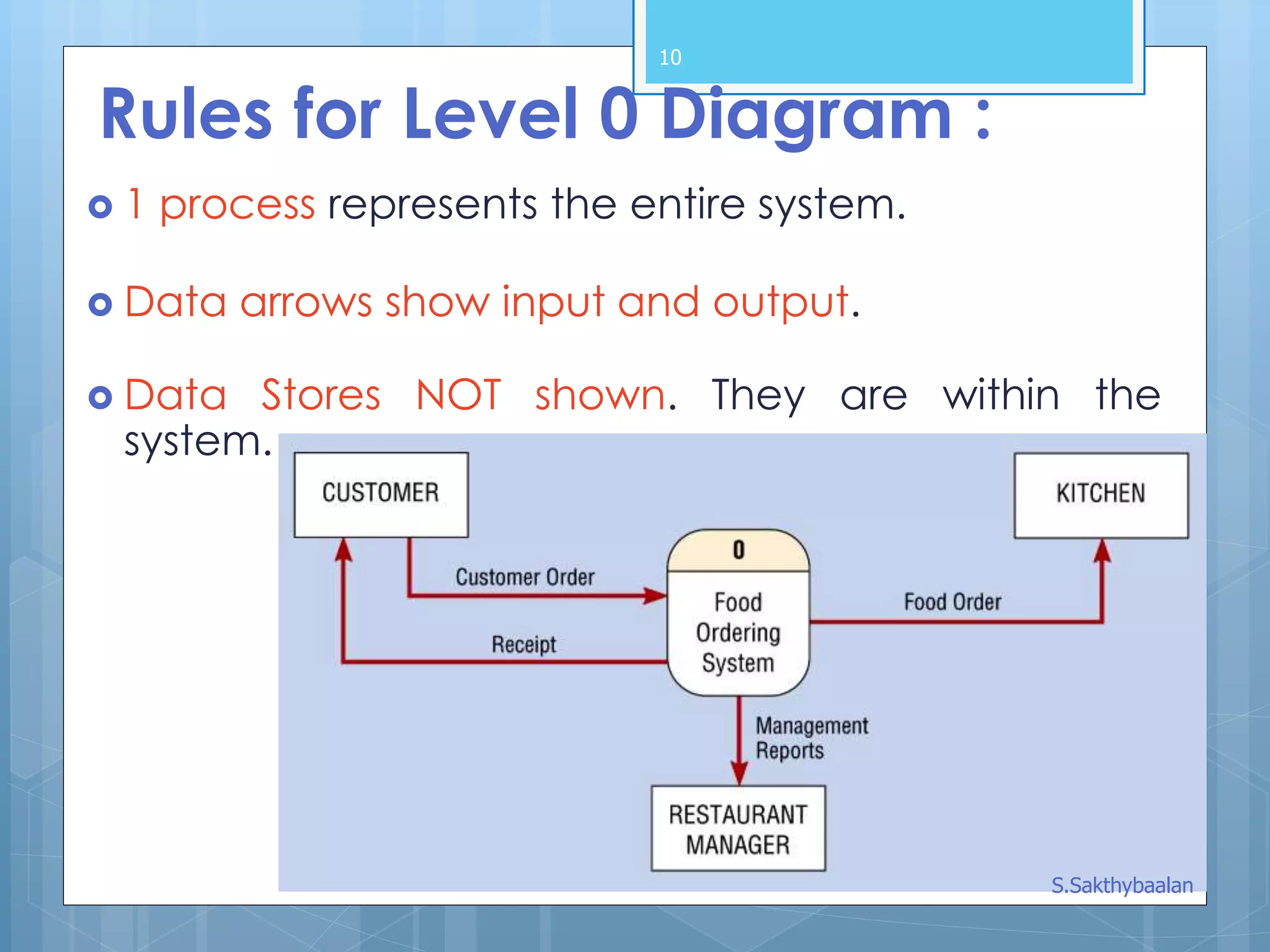
Rules for Level0 Diagram :
1 process represents the entire system.
Data arrows show input and output.
Data Stores NOT shown. They are within the
system.
S.Sakthybaalan
11.
11
Rules for Level1 Diagram :
Level 1 DFD, must balance with the context
diagram it describes.
Input going into a process are different from
outputs leaving the process.
Data stores are first shown at this level.
S.Sakthybaalan
12.
12
Rules for Level2 Diagram :
Level 2 DFD must balance with the Level 1 it
describes.
Input going into a process are different from
outputs leaving the process.
Continue to show data stores.
S.Sakthybaalan
13.
13
Numbering
On level1 processes are numbered 1,2,3…
On level 2 processes are numbered x.1, x.2, x.3…
where x is the number of the parent level 1
process.
Number is used to uniquely identify process not
to represent any order of processing
Data store numbers usually D1, D2, D3...
S.Sakthybaalan
15
Common Rules :
1.All processes must have at least one data flow in
and one data flow out.
2. All processes should modify the incoming data,
producing new forms of outgoing data.
3. Each data store must be involved with at least
one data flow.
4. Each external entity must be involved with at
least one data flow.
5. A data flow must be attached to at least one
process.
6. In DFDs, all arrows must be labeled. S.Sakthybaalan
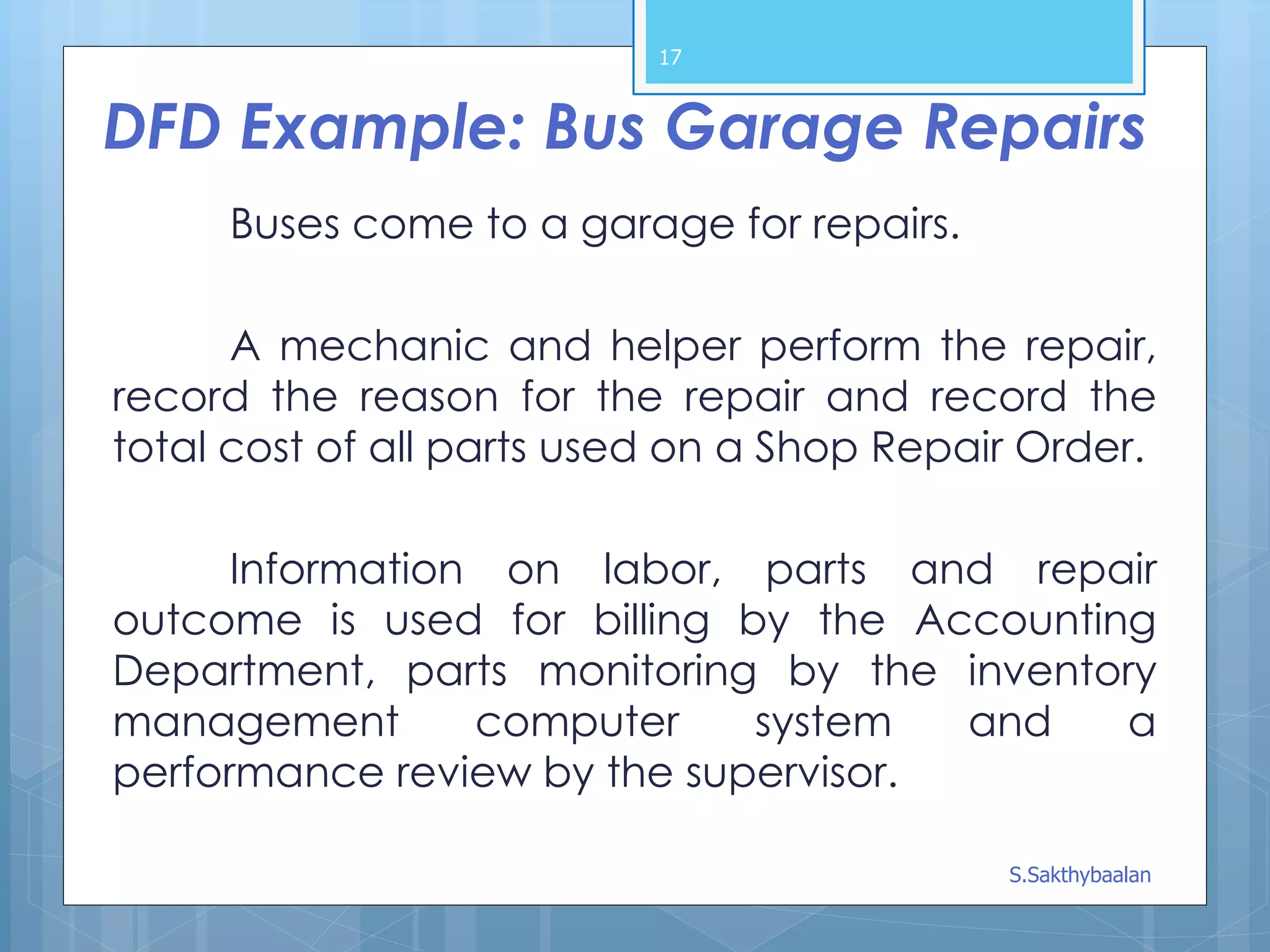
DFD Example: BusGarage Repairs
Buses come to a garage for repairs.
A mechanic and helper perform the repair,
record the reason for the repair and record the
total cost of all parts used on a Shop Repair Order.
Information on labor, parts and repair
outcome is used for billing by the Accounting
Department, parts monitoring by the inventory
management computer system and a
performance review by the supervisor.
17
S.Sakthybaalan
18.
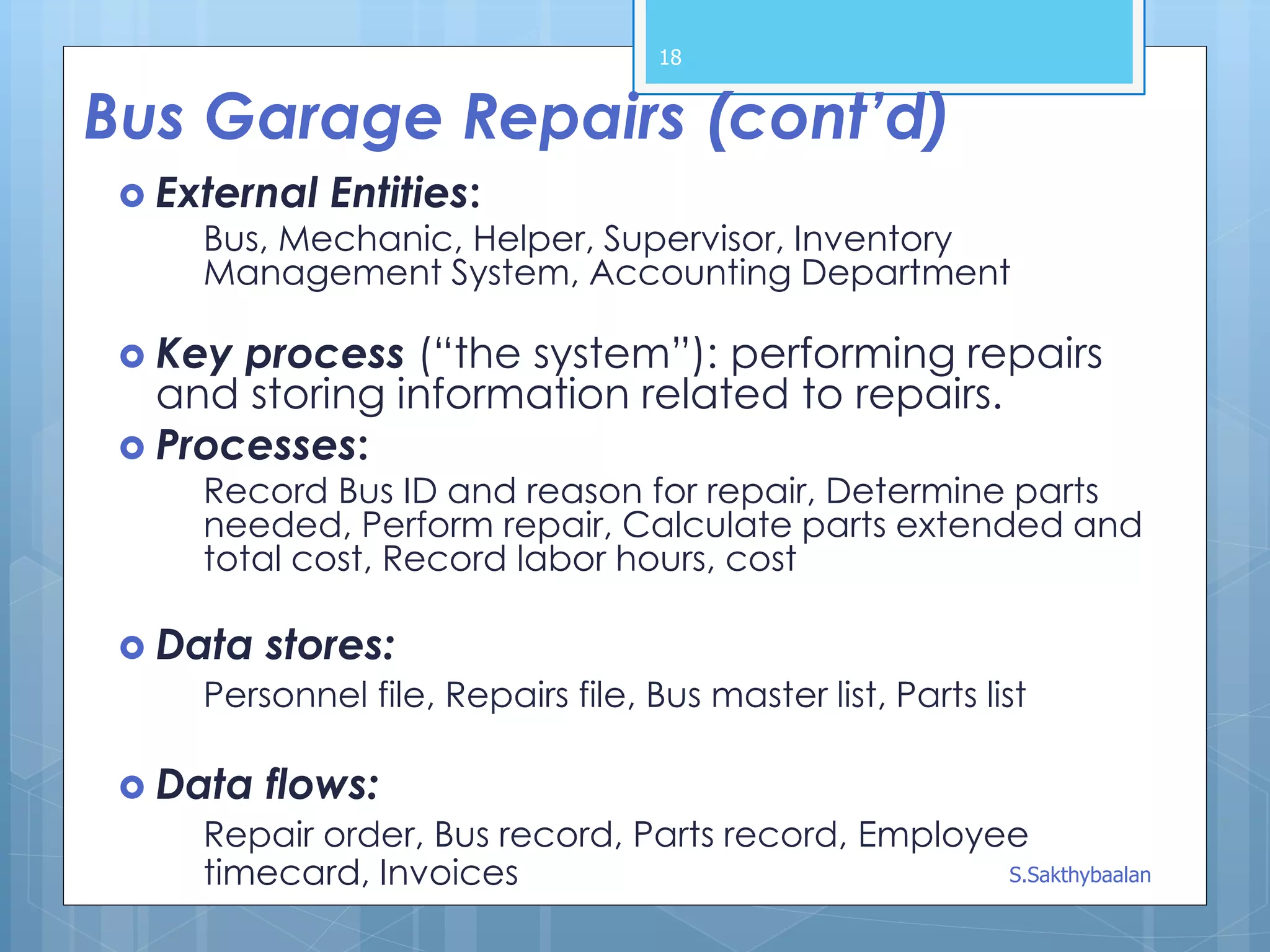
Bus Garage Repairs(cont’d)
External Entities:
Bus, Mechanic, Helper, Supervisor, Inventory
Management System, Accounting Department
Key process (“the system”): performing repairs
and storing information related to repairs.
Processes:
Record Bus ID and reason for repair, Determine parts
needed, Perform repair, Calculate parts extended and
total cost, Record labor hours, cost
Data stores:
Personnel file, Repairs file, Bus master list, Parts list
Data flows:
Repair order, Bus record, Parts record, Employee
timecard, Invoices
18
S.Sakthybaalan