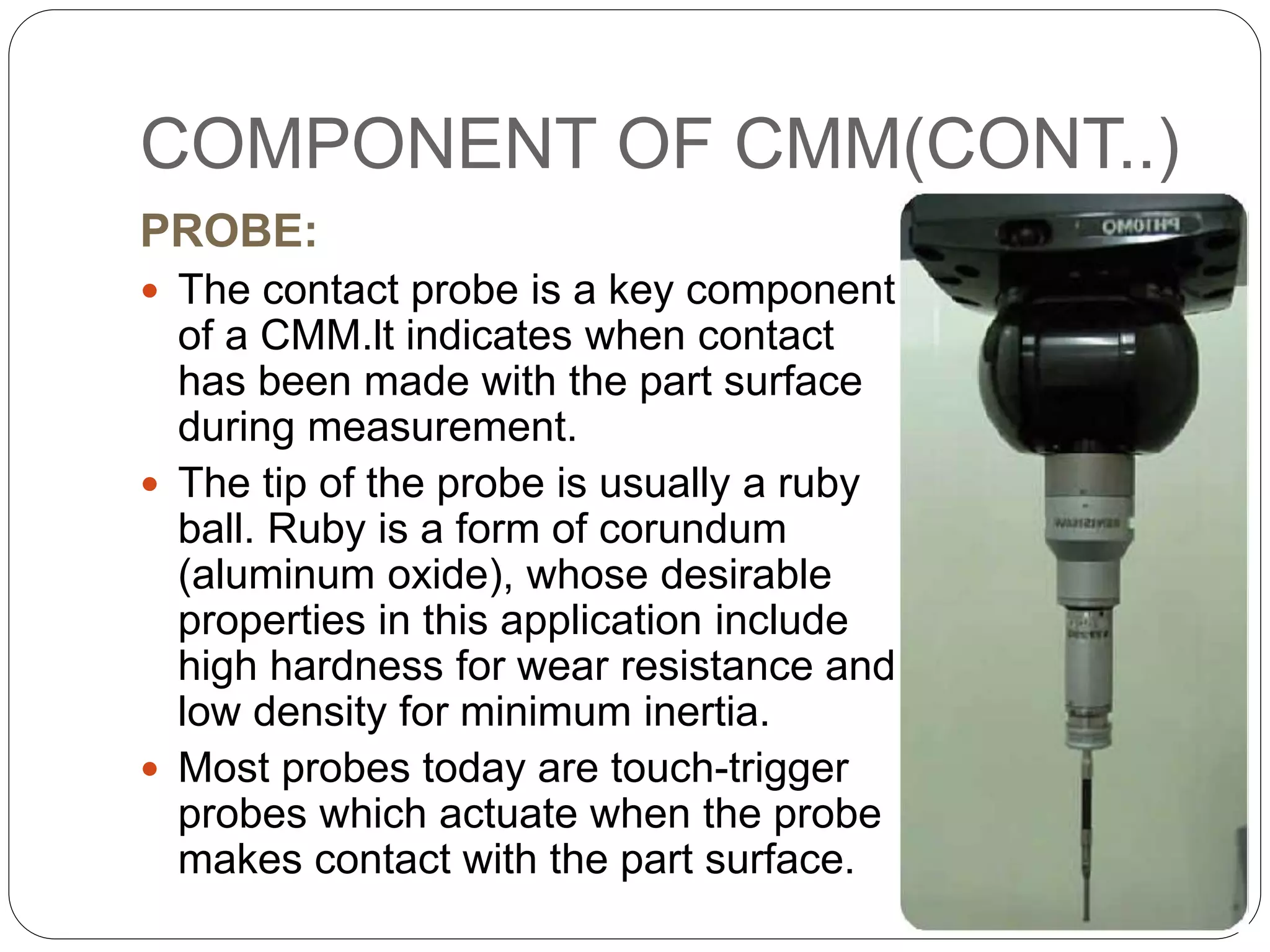
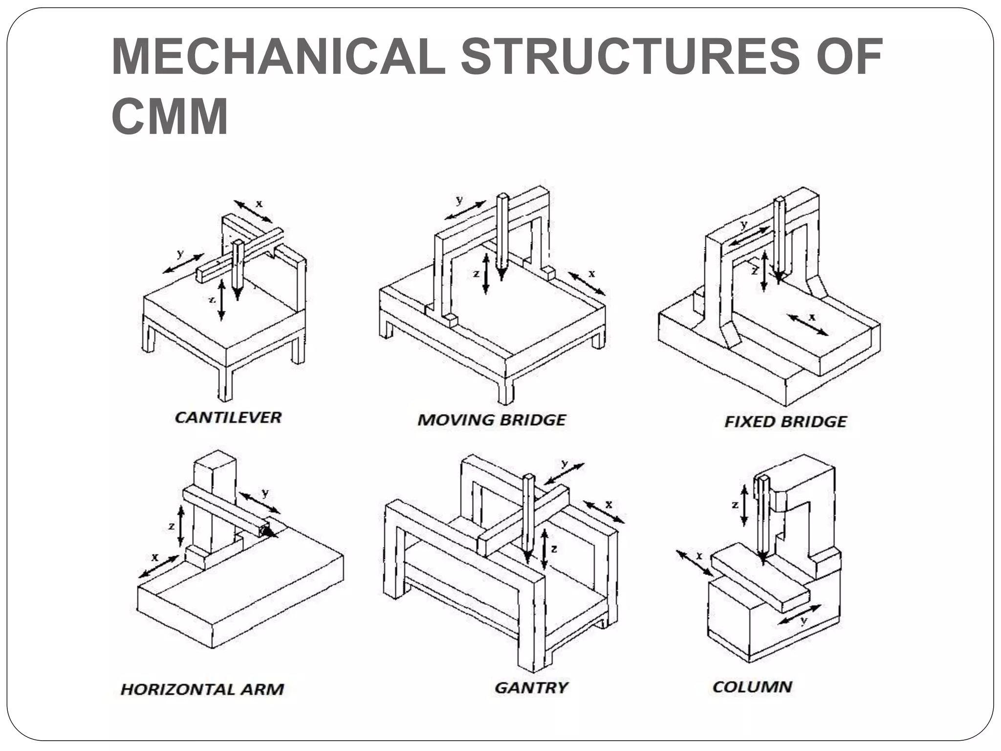
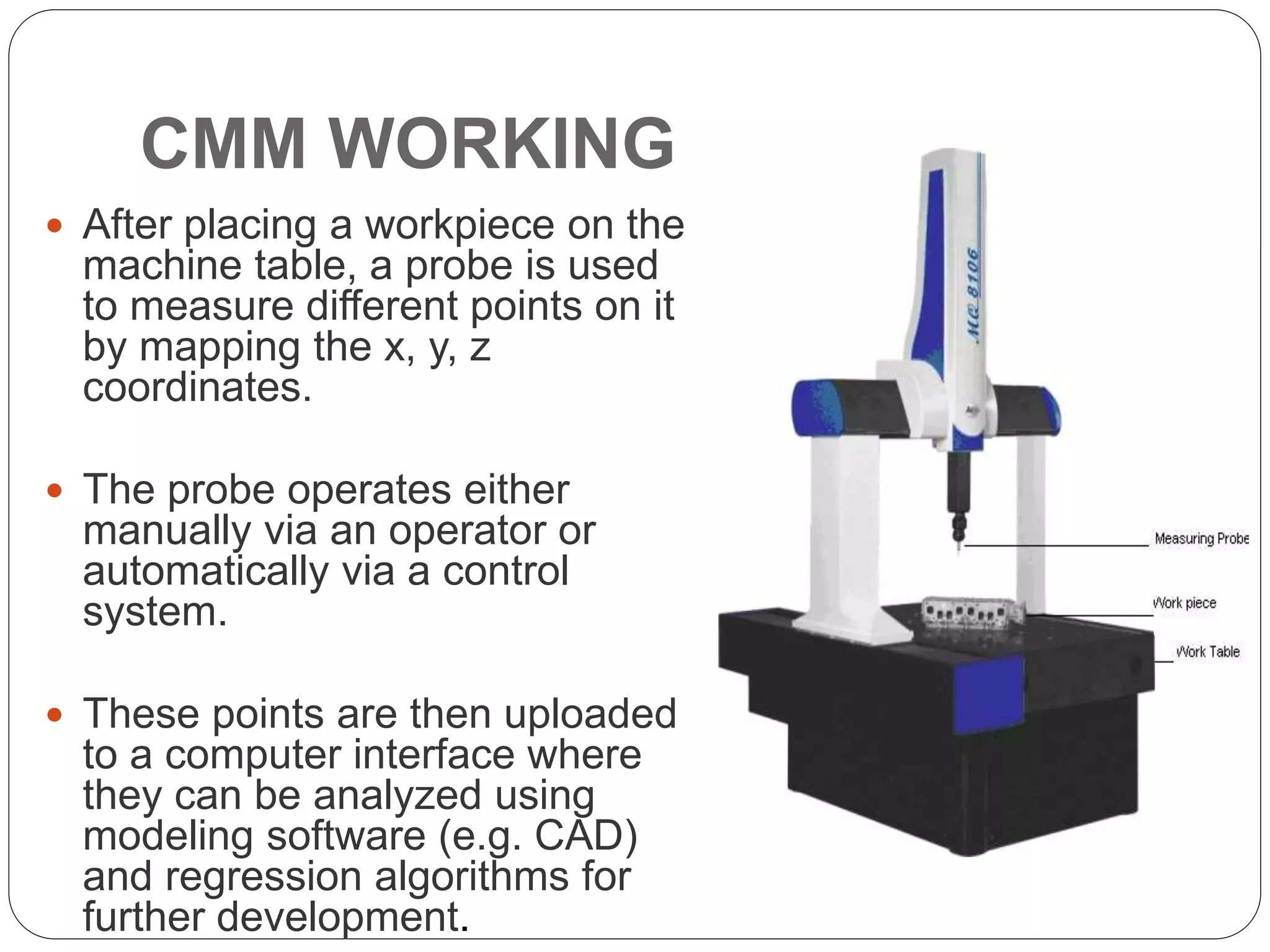
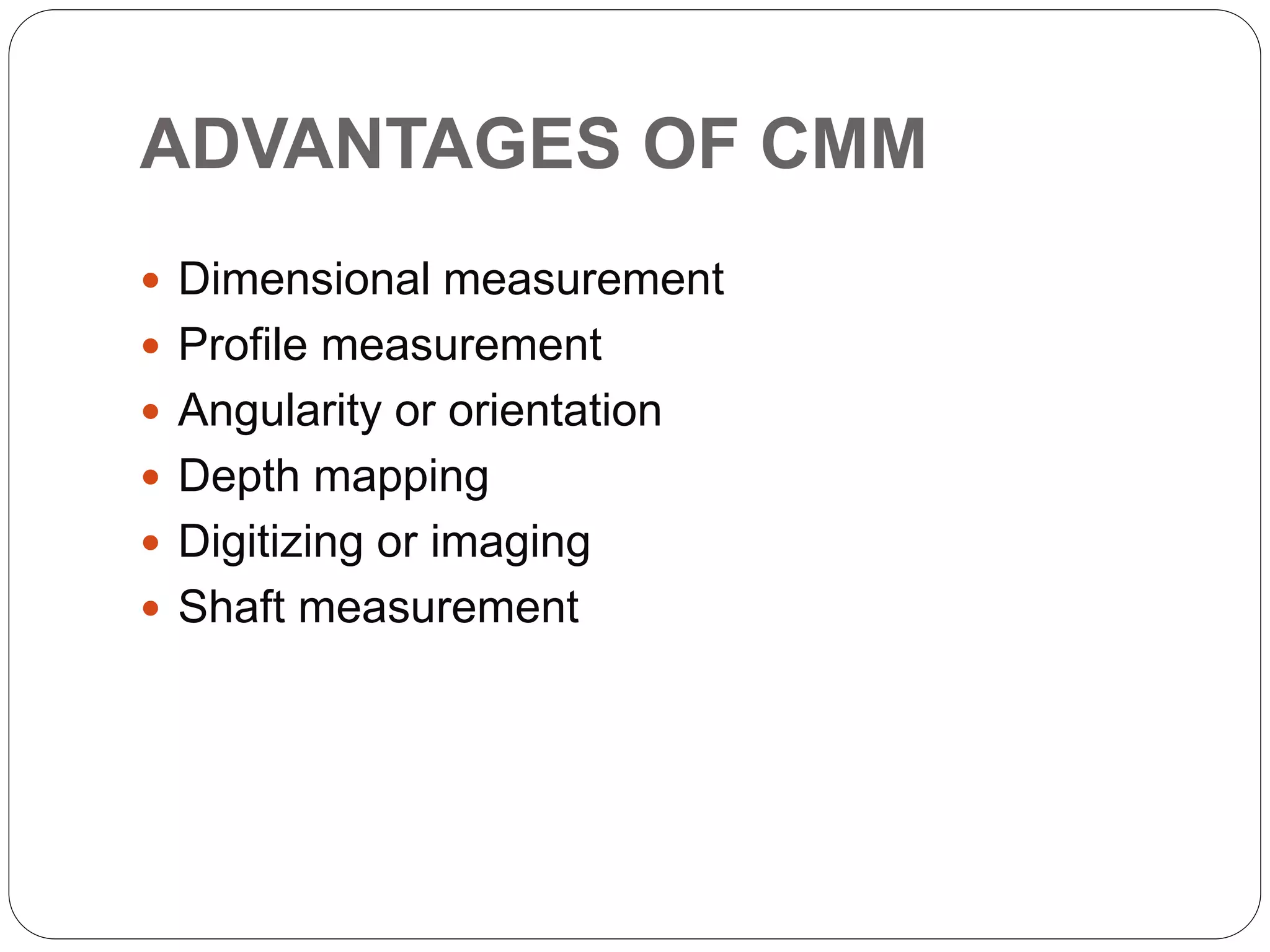
COORDINATING
MEASURING MACHINE
PRESENTATION ON
PRESENTED BY:
NIKHIL BHAGAT
(13MT07IND006)
INTRODUCTION
• Ogden developed an inspection machine in
1956,which is considered to be the first coordinate
measuring machine (CMM).
• A Coordinating measuring machine is an
electromechanical system design to perform
coordinate metrology.
• CMMs are also considered as transducers that can
convert physical measurements into electrical
signals.
• They are versatile in their capability to record
measurement of complex profiles with high
sensitivity (0.0025 mm) and speed.
COMPONENTS OF CMM
To accomplish measurements in 3-D, a basic CMM
is composed of the following components:
 Probe head and probe to contact the workpart
surfaces
 Mechanical structure that provides motion of the
probe in three Cartesian axes and displacement
transducers to measure the coordinate values of
each axis
In addition, many CMMs have the following
components:
 Drive system and control unit to move each of the
three axes
COMPONENT OF CMM(CONT..)
PROBE:
 The contact probe is a key component
of a CMM.lt indicates when contact
has been made with the part surface
during measurement.
 The tip of the probe is usually a ruby
ball. Ruby is a form of corundum
(aluminum oxide), whose desirable
properties in this application include
high hardness for wear resistance and
low density for minimum inertia.
 Most probes today are touch-trigger
probes which actuate when the probe
makes contact with the part surface.
TYPES OF CMM
Ass per the mechanical structure the CMM are
classified into
six types , which are as follows:
 CANTILEVER
 MOVING BRIDGE
 FIXED BRIDGE
 HORIZONTAL ARM
 GANTRY
 COLUMN
MECHANICAL STRUCTURES OF
CMM
CMM WORKING
 After placing a workpiece on the
machine table, a probe is used
to measure different points on it
by mapping the x, y, z
coordinates.
 The probe operates either
manually via an operator or
automatically via a control
system.
 These points are then uploaded
to a computer interface where
they can be analyzed using
modeling software (e.g. CAD)
and regression algorithms for
further development.
CMM CONTROLLING
The methods of operating and controlling a
CMM can be classified into four main
categories:
Manual drive
Manual drive with computer-assisted data
processing
Motor drive with computer-assisted data
processing
DCC with computer-assisted data processing.
ADVANTAGES OF CMM
 Dimensional measurement
 Profile measurement
 Angularity or orientation
 Depth mapping
 Digitizing or imaging
 Shaft measurement
THANK
YOU

nikhil bhagat cmm presentation

  • 1.
  • 2.
    INTRODUCTION • Ogden developedan inspection machine in 1956,which is considered to be the first coordinate measuring machine (CMM). • A Coordinating measuring machine is an electromechanical system design to perform coordinate metrology. • CMMs are also considered as transducers that can convert physical measurements into electrical signals. • They are versatile in their capability to record measurement of complex profiles with high sensitivity (0.0025 mm) and speed.
  • 3.
    COMPONENTS OF CMM Toaccomplish measurements in 3-D, a basic CMM is composed of the following components:  Probe head and probe to contact the workpart surfaces  Mechanical structure that provides motion of the probe in three Cartesian axes and displacement transducers to measure the coordinate values of each axis In addition, many CMMs have the following components:  Drive system and control unit to move each of the three axes
  • 4.
    COMPONENT OF CMM(CONT..) PROBE: The contact probe is a key component of a CMM.lt indicates when contact has been made with the part surface during measurement.  The tip of the probe is usually a ruby ball. Ruby is a form of corundum (aluminum oxide), whose desirable properties in this application include high hardness for wear resistance and low density for minimum inertia.  Most probes today are touch-trigger probes which actuate when the probe makes contact with the part surface.
  • 5.
    TYPES OF CMM Assper the mechanical structure the CMM are classified into six types , which are as follows:  CANTILEVER  MOVING BRIDGE  FIXED BRIDGE  HORIZONTAL ARM  GANTRY  COLUMN
  • 6.
  • 7.
    CMM WORKING  Afterplacing a workpiece on the machine table, a probe is used to measure different points on it by mapping the x, y, z coordinates.  The probe operates either manually via an operator or automatically via a control system.  These points are then uploaded to a computer interface where they can be analyzed using modeling software (e.g. CAD) and regression algorithms for further development.
  • 8.
    CMM CONTROLLING The methodsof operating and controlling a CMM can be classified into four main categories: Manual drive Manual drive with computer-assisted data processing Motor drive with computer-assisted data processing DCC with computer-assisted data processing.
  • 9.
    ADVANTAGES OF CMM Dimensional measurement  Profile measurement  Angularity or orientation  Depth mapping  Digitizing or imaging  Shaft measurement
  • 10.

Editor's Notes

  • #2 PRESENTED BY: NIKHIL BHAGAT (13MT07IND006)