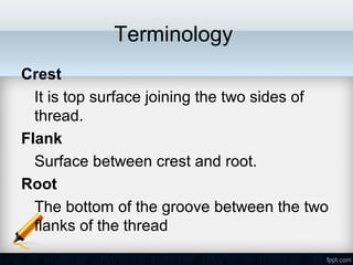
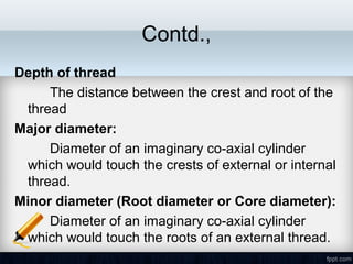
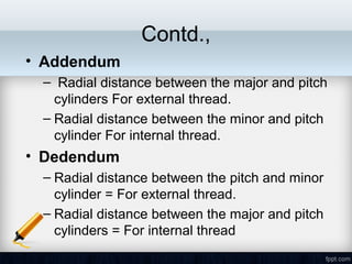
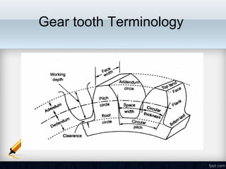
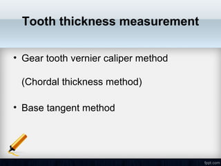
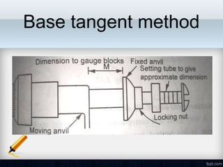
Form Measurement
Unit 3
Syllabus
Measurement of screw threads-Thread
gauges, floating carriage micrometer-
measurement of gears-tooth thickness-
constant chord and base tangent method-
Gleason gear testing machine - radius
measurements-surface finish, straightness,
flatness and roundness measurements
• Screw thread measurement
• Gear measurement
• Radius measurement
• Surface Finish measurement
• Straightness measurement
• Flatness and roundness measurements.
Screw thread
Terminology
Crest
It is top surface joining the two sides of
thread.
Flank
Surface between crest and root.
Root
The bottom of the groove between the two
flanks of the thread
Contd.,
Pitch
The distance measured parallel to the axis from a
point on a thread to the corresponding next point.
Helix angle:
The helix is the angle made by the helix of the
thread at the pitch line with the axis.
Flank angle
Angle made by the flank of a thread with the
perpendicular to the thread axis
Contd.,
Depth of thread
The distance between the crest and root of the
thread
Major diameter:
Diameter of an imaginary co-axial cylinder
which would touch the crests of external or internal
thread.
Minor diameter (Root diameter or Core diameter):
Diameter of an imaginary co-axial cylinder
which would touch the roots of an external thread.
Contd.,
• Addendum
– Radial distance between the major and pitch
cylinders For external thread.
– Radial distance between the minor and pitch
cylinder For internal thread.
• Dedendum
– Radial distance between the pitch and minor
cylinder = For external thread.
– Radial distance between the major and pitch
cylinders = For internal thread
Errors in Screw Thread
• Major diameter error
– reduction in the flank contact
– interference with the matching threads
• Minor diameter error
– Interference
– reduction of flank contact
Contd.,
• Effective diameter error
• Pitch error
– the total length of thread engaged will be either
too high or too small
• Flank angles error
• Crest and root error
Pitch Errors Classification
• Progressive error
• Periodic error
• Drunken error
• Irregular error
Errors in Thread
1) Progressive error:
The pitch of the thread is uniform but is longer or shorter
its nominal value and this is called progressive error.
Contd.,
2. Periodic error
These error repeats itself at regular intervals
along the thread.
Causes of periodic error:
•Teeth error in gears.
•Lead screw error.
•Eccentric mounting of the gears.
Contd.,
Length of thread
Cumulativepitcherror
Length of thread
Cumulativepitcherror
ERRATIC ERRORSPROGRESSIVE ERROR
Fig (c) Fig (d)
Contd.,
3) Drunken error:
Drunken errors are repeated once per turn of the thread in
a Drunken thread.
In Drunken thread the pitch measured parallel to the thread
axis. If the thread is not cut to the true helix the drunken
thread error will form
Contd.,
4) Irregular errors:
It is vary irregular manner along the length of
the thread.
Irregular error causes:
1. Machine fault.
2. Non-uniformity in the material.
3. Cutting action is not correct.
4. Machining disturbances
MEASUREMENT OF VARIOUS
ELEMENTS OF THREAD
1) Major diameter
2) Minor diameter
3) Effective or Pitch diameter
4) Pitch
5) Thread angle and form angle
Major Diameter
• Ordinary micrometer
• Bench micrometer
Measurement by Bench
micrometer:
Clamp
Fiducial
Indicator
Measuring
Anvils Holding centres
Micrometer head
Supports
BENCH MICROMETER
Measurement by Bench micrometer:
Then the cylinder is replaced by the threaded work piece and the new
reading is taken
Measurement by Bench micrometer:
Holding centre
Measuring anvil
Holding centre
Measuring anvil
StandardCylinder
ScrewThread
Measurement of Major diameter
Measurement of the major diameter of an
Internal thread:
The major diameter is usually measured by thread
comparator fitted with ball-ended styli.
First the Instrument is set for a cylindrical reference
having the same diameter of major diameter of internal
thread and the reading is taken.
 Then the floating head is retracted to engage the tips of
the styli at the root of spring under pressure.
For that the new reading is taken,
Measurement of the major diameter of an
Internal thread:
Measurement of Minor diameter
The minor diameter is measured by a
comparative method by using floating carriage
diameter measuring machine and small ‘ V pieces
which make contact with the root of the thread.
These V pieces are made in several sizes,
having suitable radii at the edges.
 V pieces are made of hardened steel.
The floating carriage diameter-measuring
machine is a bench micrometer mounted on a
carriage.
Measurement of Minor diameter
The threaded work piece is mounted between the centers of
the instrument and the.V pieces are placed on each side of
the work piece and then the reading is noted.
After taking this reading the work piece is then replaced by
a standard reference cylindrical setting gauge.
Measurement of Minor diameter
of Internal threads:
The Minor diameter of Internal threads
are measured by
1. Using taper parallels
2. Using Rollers.
Measurement of Minor diameter
of Internal threads:
1. Using taper parallels:
 For diameters less than 200mm the use of Taper
parallels and micrometer is very common.
 The taper parallels are pairs of wedges having reduced
and parallel outer edges.
 The diameter across their outer edges can be changed
by sliding them over each other.
Measurement of Minor diameter
of Internal threads:
Using rollers:
 For more than 200mm diameter this method is
used. Precision rollers are inserted inside the thread
and proper slip gauge is inserted between the rollers.
The minor diameter is then the length of slip gauges
plus twice the diameter of roller.
Measurement of Effective Diameter
• One wire
• Two Wires
• Three wires method
One wire method
Two wire method
In this method wires of suitable size are
placed between the standard and the
micrometer anvils
Three Wire Method
Pitch measurement
• Pitch measuring machine
• Tool makers microscope
• Screw pitch gauge
Pitch measuring machine
Tool makers microscope
Thread form and flank angle measurement
• Thread gauge
• Ring gauge
• Optical projectors
Gear Measurement
Types of gears
– Spur gear
– Spiral gear
– Helical gears
– Bevel gears
– Worm and Worm wheel
– Rack and Pinion:
Gear tooth Terminology
• Tooth profile
– It is the shape of any side of gear tooth in its
cross section
• Pitch circle
– It is the imaginary circle of gear that rolls without
slipping over the circle of its mating gear.
• Addendum circle
– The circle coincides with the crests (or) tops of
teeth.
• Dedendum circle (or) Root circle
– This circle coincides with the roots (or) bottom on
teeth
• Module(m)
– It is the ratio of pitch circle diameter to the
total number of teeth
• Face
– Part of the tooth in the axial plane lying
between tip circle and pitch circle.
• Flank
– Part of the tooth lying between pitch circle and
root circle.
• Top land
– Top surface of a tooth
Gear Errors
• Profile error
– The maximum distance of any point on the tooth
profile form to the design profile.
• Pitch error
– Difference between actual and design pitch
• Cyclic error
– Error occurs in each revolution of gear
• Run out: -
– Total range of reading of a fixed indicator with the
contact points applied to a surface rotated,
without axial movement, about a fixed axis
Gear Errors
• Eccentricity: -
– Half the radial run out
• Wobble
– Run out measured parallel to. the axis of
rotation at a specified distance from the axis
• Radial run out
– Run out measured along a perpendicular to
the axis of rotation.
Gear Errors
• Eccentricity: -
– Half the radial run out
• Wobble
– Run out measured parallel to. the axis of
rotation at a specified distance from the axis
• Radial run out
– Run out measured along a perpendicular to
the axis of rotation.
Gear Errors
• Axial run out
– Run out measured parallel to the axis of
rotation at a speed
• Periodic error
– Error occurring at regular intervals
GEAR MEASUREMENT
1. Run out
2. Pitch
3. Profile
4. Back lash
5. Tooth thickness
6. Alignment
Run out
• In the testing the gears are placed in the
mandrel and the dial indicator of the tester
possesses special tip depending upon the
module of the gear and the tips inserted
between the tooth spaces and the gears
are rotated tooth by tooth and the variation
is noted from the dial! indicator
Pitch measurement
• Point to point measurement (i.e. One tooth
point to next toot point)
• Direct angular measurement
Tooth to Tooth measurement
Direct Angular Measurement
• Measuring the error by using set dial gauge
against a tooth in this method the position of a
suitable point on a tooth is measured after the
gear has been indexed by a suitable angle
• If the gear is not indexed through the angular
pitch the reading differs from the original
reading.
• The difference between these is the cumulative
pitch error
Profile checking
• Optical projection method
• Involute measuring machine
Involute measuring machine
Backlash
• Backlash is the distance through which a
gear can be rotated to bring its
nonworking flank in contact with the teeth
of mating gear
• The determination of backlash is, first one
of the two gears of the pair is locked, while
other is rotated forward and backward and
by the comparator the maximum
displacement its measured
Tooth thickness measurement
• Gear tooth vernier caliper method
(Chordal thickness method)
• Base tangent method
Gear tooth vernier caliper
Base tangent method

Form measurement

  • 1.
  • 2.
    Syllabus Measurement of screwthreads-Thread gauges, floating carriage micrometer- measurement of gears-tooth thickness- constant chord and base tangent method- Gleason gear testing machine - radius measurements-surface finish, straightness, flatness and roundness measurements
  • 3.
    • Screw threadmeasurement • Gear measurement • Radius measurement • Surface Finish measurement • Straightness measurement • Flatness and roundness measurements.
  • 4.
  • 5.
    Terminology Crest It is topsurface joining the two sides of thread. Flank Surface between crest and root. Root The bottom of the groove between the two flanks of the thread
  • 6.
    Contd., Pitch The distance measuredparallel to the axis from a point on a thread to the corresponding next point. Helix angle: The helix is the angle made by the helix of the thread at the pitch line with the axis. Flank angle Angle made by the flank of a thread with the perpendicular to the thread axis
  • 7.
    Contd., Depth of thread Thedistance between the crest and root of the thread Major diameter: Diameter of an imaginary co-axial cylinder which would touch the crests of external or internal thread. Minor diameter (Root diameter or Core diameter): Diameter of an imaginary co-axial cylinder which would touch the roots of an external thread.
  • 8.
    Contd., • Addendum – Radialdistance between the major and pitch cylinders For external thread. – Radial distance between the minor and pitch cylinder For internal thread. • Dedendum – Radial distance between the pitch and minor cylinder = For external thread. – Radial distance between the major and pitch cylinders = For internal thread
  • 9.
    Errors in ScrewThread • Major diameter error – reduction in the flank contact – interference with the matching threads • Minor diameter error – Interference – reduction of flank contact
  • 10.
    Contd., • Effective diametererror • Pitch error – the total length of thread engaged will be either too high or too small • Flank angles error • Crest and root error
  • 11.
    Pitch Errors Classification •Progressive error • Periodic error • Drunken error • Irregular error
  • 12.
    Errors in Thread 1)Progressive error: The pitch of the thread is uniform but is longer or shorter its nominal value and this is called progressive error.
  • 13.
    Contd., 2. Periodic error Theseerror repeats itself at regular intervals along the thread. Causes of periodic error: •Teeth error in gears. •Lead screw error. •Eccentric mounting of the gears.
  • 14.
    Contd., Length of thread Cumulativepitcherror Lengthof thread Cumulativepitcherror ERRATIC ERRORSPROGRESSIVE ERROR Fig (c) Fig (d)
  • 15.
    Contd., 3) Drunken error: Drunkenerrors are repeated once per turn of the thread in a Drunken thread. In Drunken thread the pitch measured parallel to the thread axis. If the thread is not cut to the true helix the drunken thread error will form
  • 16.
    Contd., 4) Irregular errors: Itis vary irregular manner along the length of the thread. Irregular error causes: 1. Machine fault. 2. Non-uniformity in the material. 3. Cutting action is not correct. 4. Machining disturbances
  • 17.
    MEASUREMENT OF VARIOUS ELEMENTSOF THREAD 1) Major diameter 2) Minor diameter 3) Effective or Pitch diameter 4) Pitch 5) Thread angle and form angle
  • 18.
    Major Diameter • Ordinarymicrometer • Bench micrometer
  • 19.
    Measurement by Bench micrometer: Clamp Fiducial Indicator Measuring AnvilsHolding centres Micrometer head Supports BENCH MICROMETER
  • 20.
    Measurement by Benchmicrometer: Then the cylinder is replaced by the threaded work piece and the new reading is taken
  • 21.
  • 22.
    Measurement by Benchmicrometer: Holding centre Measuring anvil Holding centre Measuring anvil StandardCylinder ScrewThread Measurement of Major diameter
  • 23.
    Measurement of themajor diameter of an Internal thread: The major diameter is usually measured by thread comparator fitted with ball-ended styli. First the Instrument is set for a cylindrical reference having the same diameter of major diameter of internal thread and the reading is taken.  Then the floating head is retracted to engage the tips of the styli at the root of spring under pressure. For that the new reading is taken,
  • 24.
    Measurement of themajor diameter of an Internal thread:
  • 25.
    Measurement of Minordiameter The minor diameter is measured by a comparative method by using floating carriage diameter measuring machine and small ‘ V pieces which make contact with the root of the thread. These V pieces are made in several sizes, having suitable radii at the edges.  V pieces are made of hardened steel. The floating carriage diameter-measuring machine is a bench micrometer mounted on a carriage.
  • 26.
  • 27.
    The threaded workpiece is mounted between the centers of the instrument and the.V pieces are placed on each side of the work piece and then the reading is noted. After taking this reading the work piece is then replaced by a standard reference cylindrical setting gauge. Measurement of Minor diameter
  • 28.
    Measurement of Minordiameter of Internal threads: The Minor diameter of Internal threads are measured by 1. Using taper parallels 2. Using Rollers.
  • 29.
    Measurement of Minordiameter of Internal threads: 1. Using taper parallels:  For diameters less than 200mm the use of Taper parallels and micrometer is very common.  The taper parallels are pairs of wedges having reduced and parallel outer edges.  The diameter across their outer edges can be changed by sliding them over each other.
  • 30.
    Measurement of Minordiameter of Internal threads: Using rollers:  For more than 200mm diameter this method is used. Precision rollers are inserted inside the thread and proper slip gauge is inserted between the rollers. The minor diameter is then the length of slip gauges plus twice the diameter of roller.
  • 31.
    Measurement of EffectiveDiameter • One wire • Two Wires • Three wires method
  • 32.
  • 33.
    Two wire method Inthis method wires of suitable size are placed between the standard and the micrometer anvils
  • 34.
  • 35.
    Pitch measurement • Pitchmeasuring machine • Tool makers microscope • Screw pitch gauge
  • 36.
  • 37.
  • 38.
    Thread form andflank angle measurement • Thread gauge • Ring gauge • Optical projectors
  • 39.
    Gear Measurement Types ofgears – Spur gear – Spiral gear – Helical gears – Bevel gears – Worm and Worm wheel – Rack and Pinion:
  • 40.
  • 41.
    • Tooth profile –It is the shape of any side of gear tooth in its cross section • Pitch circle – It is the imaginary circle of gear that rolls without slipping over the circle of its mating gear. • Addendum circle – The circle coincides with the crests (or) tops of teeth. • Dedendum circle (or) Root circle – This circle coincides with the roots (or) bottom on teeth
  • 42.
    • Module(m) – Itis the ratio of pitch circle diameter to the total number of teeth • Face – Part of the tooth in the axial plane lying between tip circle and pitch circle. • Flank – Part of the tooth lying between pitch circle and root circle. • Top land – Top surface of a tooth
  • 43.
    Gear Errors • Profileerror – The maximum distance of any point on the tooth profile form to the design profile. • Pitch error – Difference between actual and design pitch • Cyclic error – Error occurs in each revolution of gear • Run out: - – Total range of reading of a fixed indicator with the contact points applied to a surface rotated, without axial movement, about a fixed axis
  • 44.
    Gear Errors • Eccentricity:- – Half the radial run out • Wobble – Run out measured parallel to. the axis of rotation at a specified distance from the axis • Radial run out – Run out measured along a perpendicular to the axis of rotation.
  • 45.
    Gear Errors • Eccentricity:- – Half the radial run out • Wobble – Run out measured parallel to. the axis of rotation at a specified distance from the axis • Radial run out – Run out measured along a perpendicular to the axis of rotation.
  • 46.
    Gear Errors • Axialrun out – Run out measured parallel to the axis of rotation at a speed • Periodic error – Error occurring at regular intervals
  • 47.
    GEAR MEASUREMENT 1. Runout 2. Pitch 3. Profile 4. Back lash 5. Tooth thickness 6. Alignment
  • 48.
    Run out • Inthe testing the gears are placed in the mandrel and the dial indicator of the tester possesses special tip depending upon the module of the gear and the tips inserted between the tooth spaces and the gears are rotated tooth by tooth and the variation is noted from the dial! indicator
  • 49.
    Pitch measurement • Pointto point measurement (i.e. One tooth point to next toot point) • Direct angular measurement
  • 50.
    Tooth to Toothmeasurement
  • 51.
    Direct Angular Measurement •Measuring the error by using set dial gauge against a tooth in this method the position of a suitable point on a tooth is measured after the gear has been indexed by a suitable angle • If the gear is not indexed through the angular pitch the reading differs from the original reading. • The difference between these is the cumulative pitch error
  • 52.
    Profile checking • Opticalprojection method • Involute measuring machine
  • 53.
  • 54.
    Backlash • Backlash isthe distance through which a gear can be rotated to bring its nonworking flank in contact with the teeth of mating gear • The determination of backlash is, first one of the two gears of the pair is locked, while other is rotated forward and backward and by the comparator the maximum displacement its measured
  • 55.
    Tooth thickness measurement •Gear tooth vernier caliper method (Chordal thickness method) • Base tangent method
  • 56.
  • 57.