Downloaded 88 times
![Diode – Operational
Principle
Yong Heui Cho @ Mokwon University
Some of slides are referred to:
[1] A. S. Sedra & K. C. Smith, Microelectronic Circuits.](https://image.slidesharecdn.com/4-151002071323-lva1-app6892/75/Diode-Operational-Principle-1-2048.jpg)

![13
V Measurement
• Voltmeter
– Cut-in voltage: almost 0.7 [V]
forward](https://image.slidesharecdn.com/4-151002071323-lva1-app6892/75/Diode-Operational-Principle-13-2048.jpg)


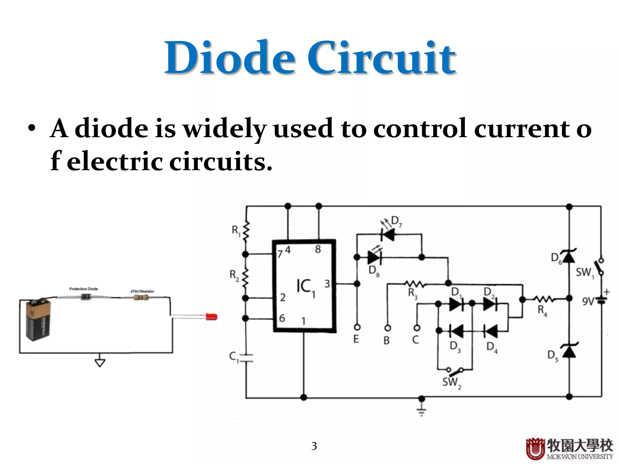
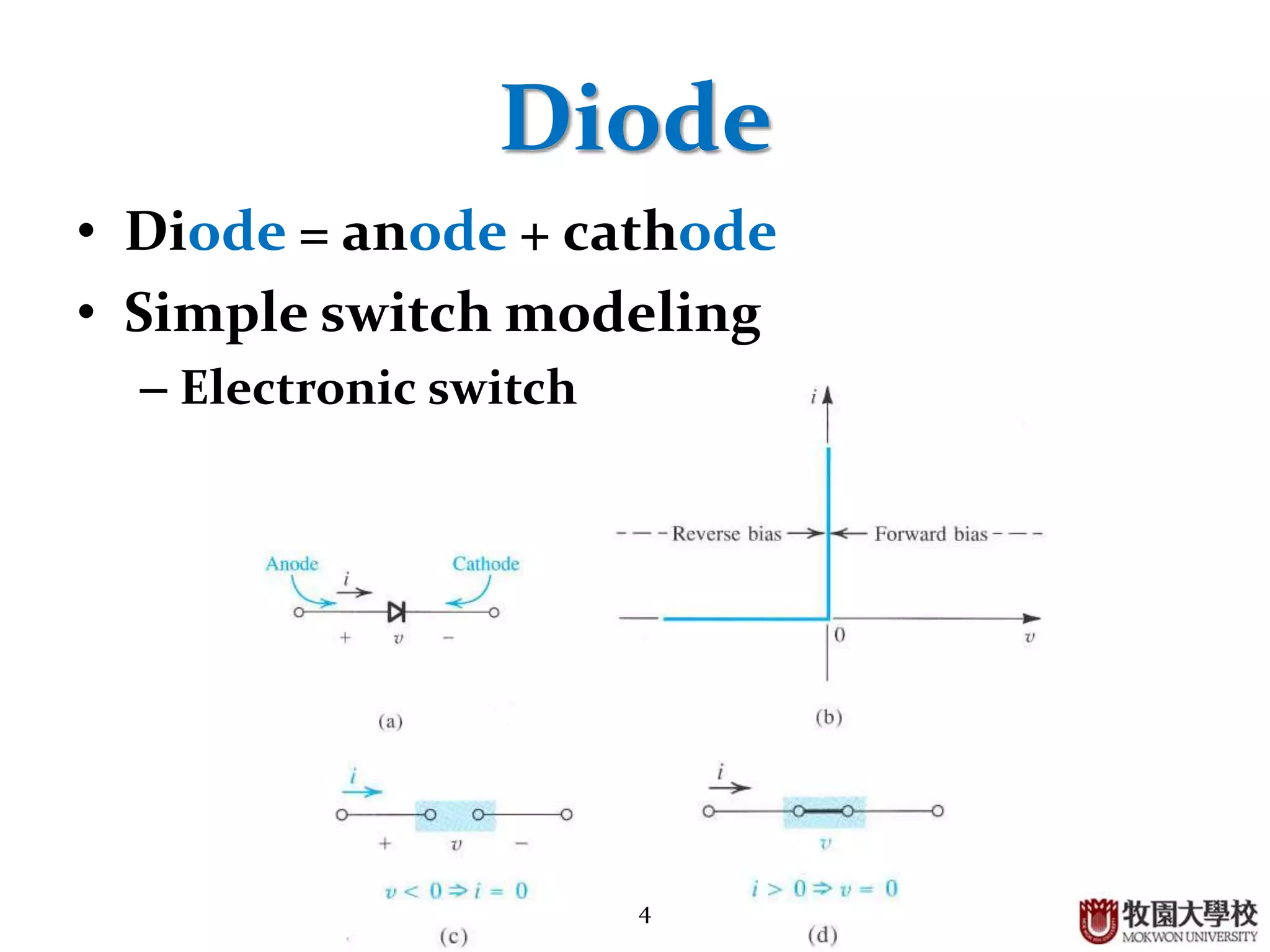
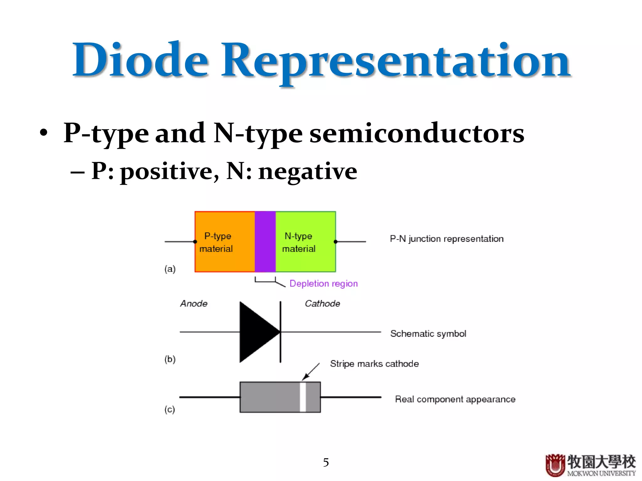
This document discusses the operational principle of diodes. It begins by introducing diodes and their use to control electric circuit current. Diodes are composed of an anode and cathode and can be modeled as a simple electronic switch. They are made by doping silicon with impurities to create either a p-type or n-type semiconductor, which form a p-n junction when joined. A diode acts as a closed switch under forward bias when positive is applied to the anode, and as an open switch under reverse bias. In the depletion region of a p-n junction, an insulating region is formed. Diodes have applications in rectification circuits and as light sources in LEDs.
Overview of diode operation, importance in electronic circuits, and introductory content.
Functionality of diode as a switch, structure (anode + cathode), and types of semiconductors (P-type, N-type).
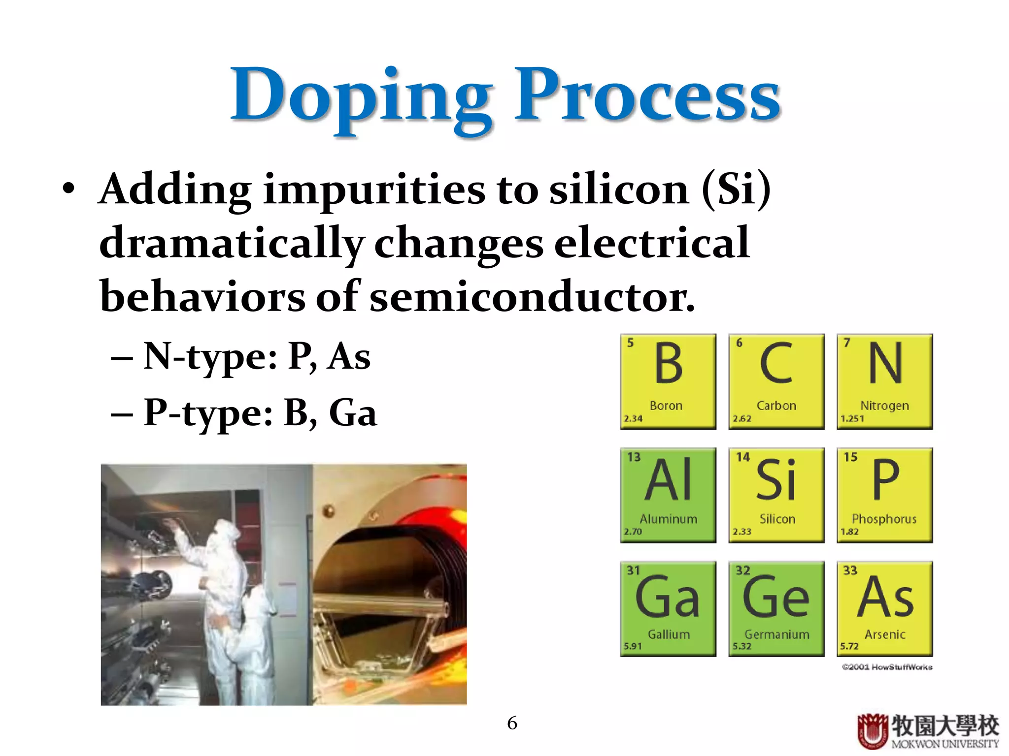
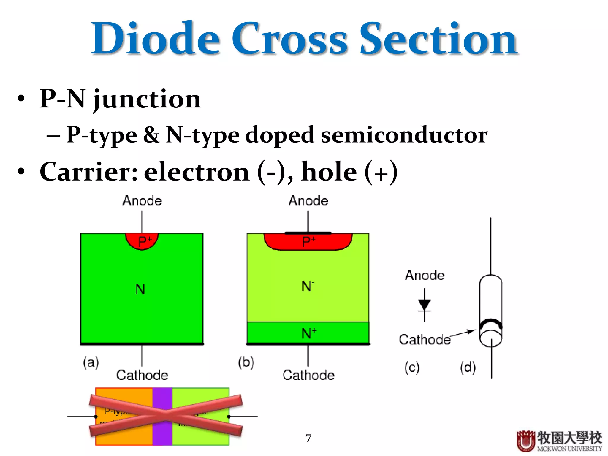
Process of doping silicon to create N-type and P-type semiconductors, and explanation of diode cross-section.
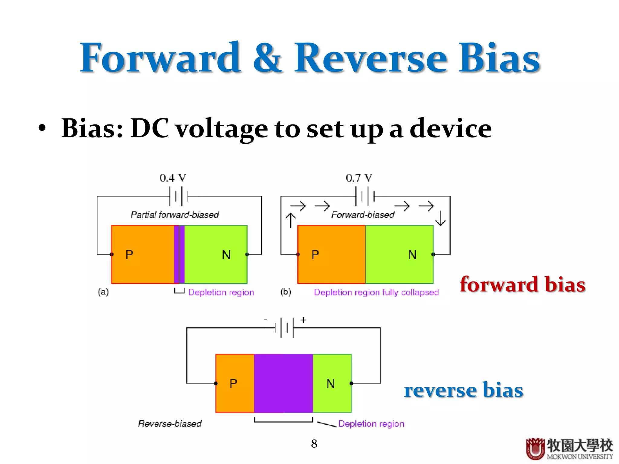
Concepts of forward and reverse bias, including conditions affecting the depletion region.
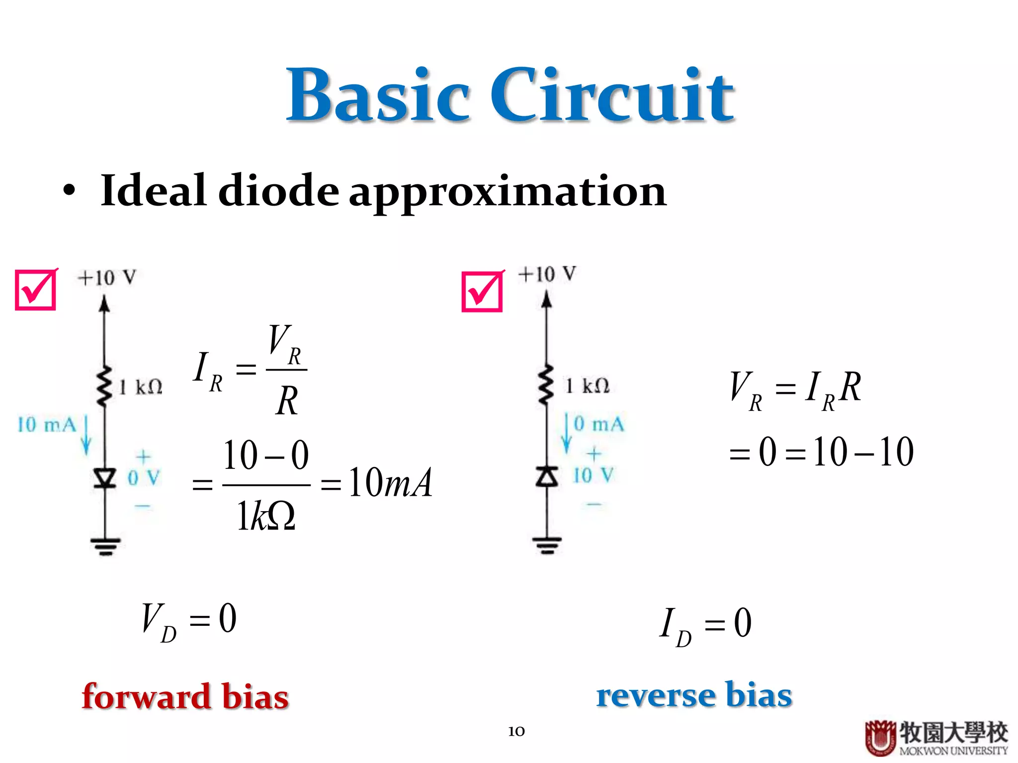
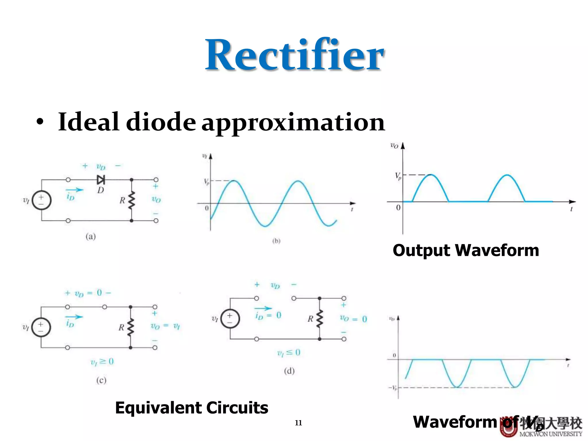
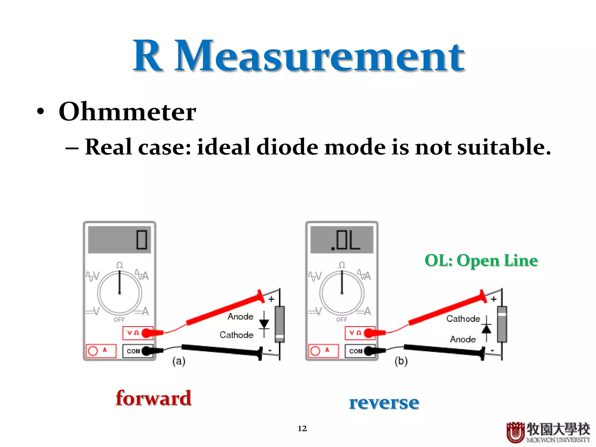
Ideal diode behavior, basic circuit applications, rectifier output waveforms, and limitations of measurement instruments.
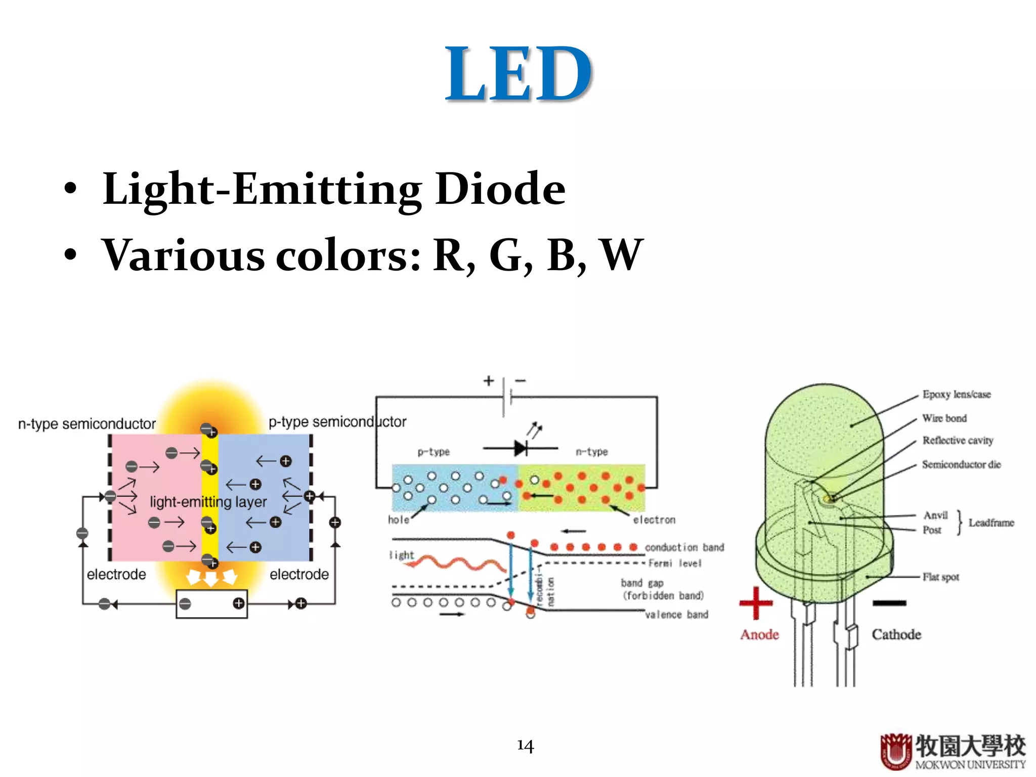
Overview of Light Emitting Diodes (LED) including color varieties and highlighting GaN Blue diode advancements.


![Vibe Coding vs. Spec-Driven Development [Free Meetup]](https://cdn.slidesharecdn.com/ss_thumbnails/vibecodingvsspecdrivendevelopment-251209105622-43f455e7-thumbnail.jpg?width=640&height=640&fit=bounds)

