Downloaded 548 times
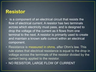


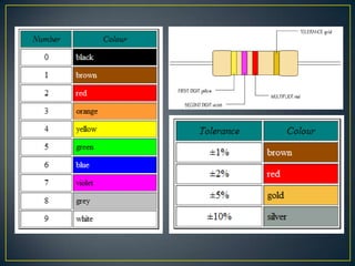


A resistor is an electrical component that opposes or resists the flow of electric current. It works by converting electrical energy into heat energy as current passes through it. Resistors are commonly used to regulate current and voltage levels in electronic circuits. They come in various types defined by their material and manufacturing process, and their resistance values are color coded for easy identification.