Downloaded 129 times
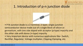
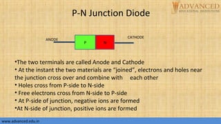
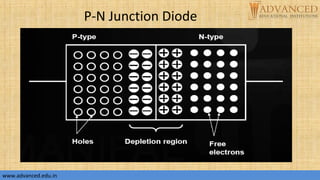
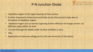
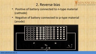
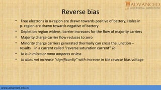
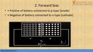
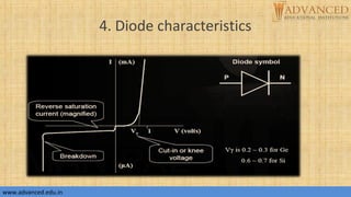
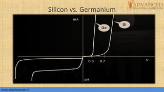
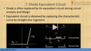
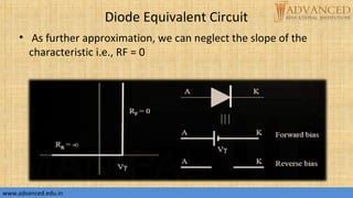
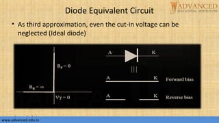
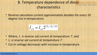


The document provides an overview of p-n junction diodes, explaining their structure, function, and various applications such as switches and rectifiers. It covers concepts such as reverse and forward bias, diode characteristics, current equations, resistances, equivalent circuits, temperature dependence, and breakdown regions. Key mechanisms like avalanche and zener breakdown are also discussed, along with their implications for diode performance.
![[FULL ANIMATED(Download to view)] Unbiased diode, Forward biased , reverse bi...](https://cdn.slidesharecdn.com/ss_thumbnails/edc-141002103245-phpapp02-thumbnail.jpg?width=640&height=640&fit=bounds)