Download as PDF, PPTX
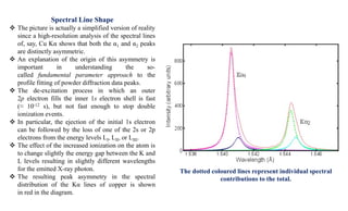
![Spectral Intensity
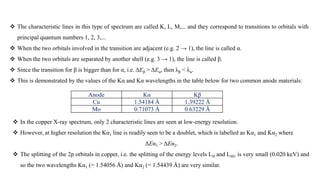
The intensity of the Kα1 peak is almost exactly double the intensity of the Kα2 peak.
The intensity of a K line is given approximately by the formula
IK = c i (V - VK)n
Where
i is the electron beam current,
c is a constant, and
VK is the excitation potential of the K line (as given earlier by VK = 12.398 [kV/Å] / λ ).
The exponent n is approximately 1.5, but drops towards 1.0 when V > 2VK.
The ratio IK : Iwhite is a maximum when the accelerating voltage V is approximately 4× the excitation potential VK.
For a Cu Kα anode, where VK is 8.0 kV, run with a typical operating voltage of 40 kV, the Kα line is approximately
90× more intense than the white radiation of a similar wavelength.
Thus the white radiation from a copper anode is too weak to be of any practical use for powder diffraction in the
laboratory.
What about the intensity of the Kβ radiation?
Again considering a copper anode, the intensity of the Kα lines is approximately 5 times that of Kβ. Hence, all
instrumental setups are optimized around the Kα radiation, and preferably around Kα1 when high resolution
monochromators are used as part of the X-ray optics.](https://image.slidesharecdn.com/xrayandxrd-230913104957-db803c7e/85/X-Rays-The-basic-understanding-of-XRD-analysis-8-320.jpg)


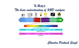
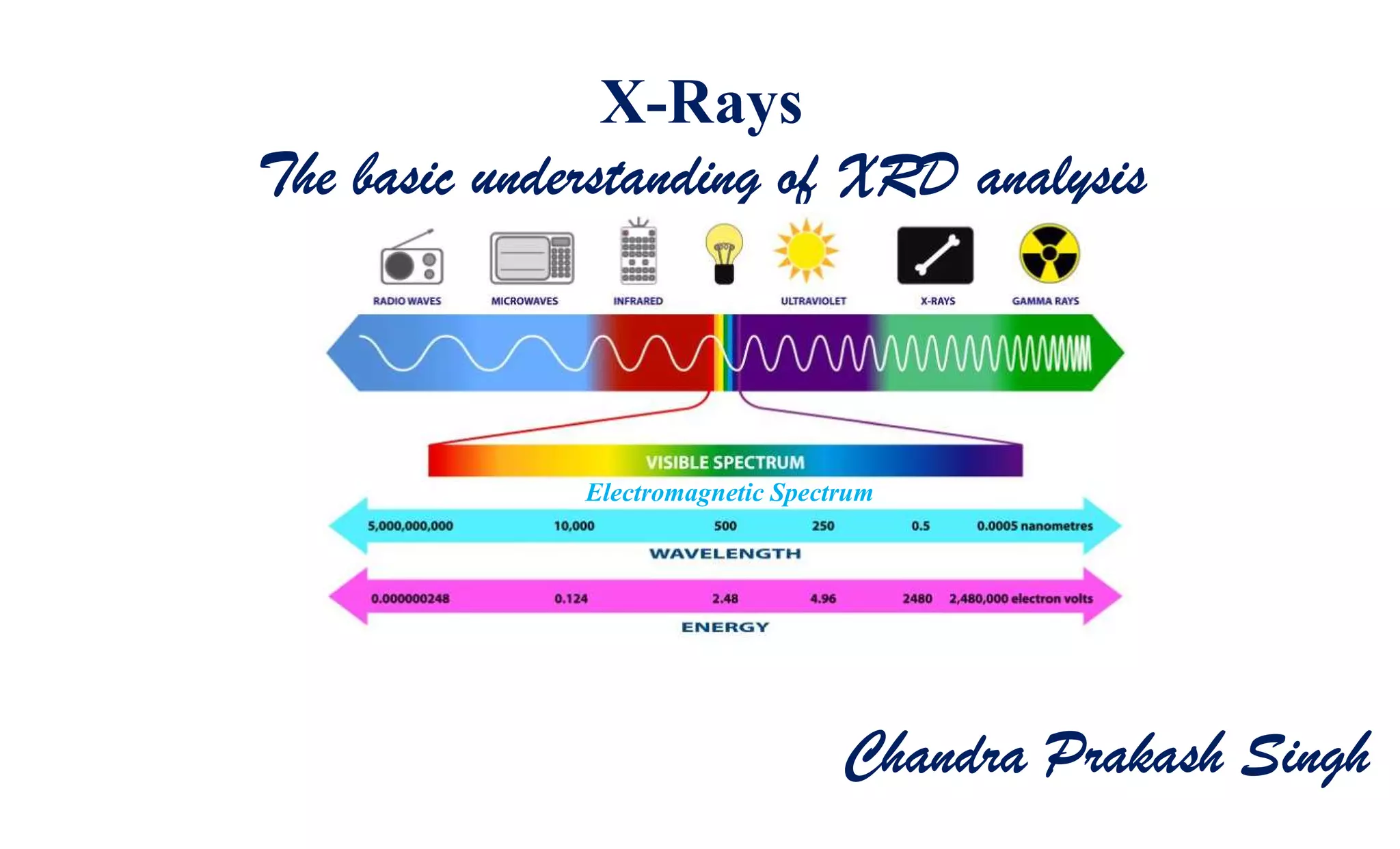
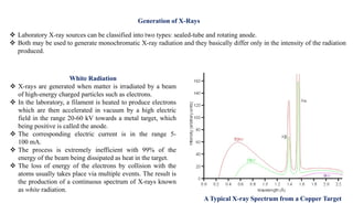
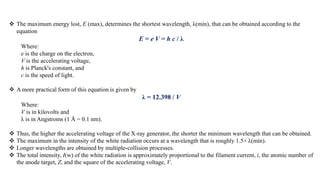
The document discusses the principles of X-ray diffraction (XRD) analysis, detailing the generation of X-rays via laboratory sources, specifically sealed-tube and rotating anode systems. It explains the concepts of white radiation and characteristic radiation, including their spectral lines, intensity, and the effects of various anode materials on the resulting wavelengths. Furthermore, it touches on the importance of filters in XRD setups to achieve monochromatic X-ray sources for accurate powder diffraction analysis.


